• Tags
  • Documentation
  • Order
  • Register
  • Login
Duet3D Logo Duet3D
  • Tags
  • Documentation
  • Order
  • Register
  • Login

ST3Di Modelsmart 280 - Duet Maestro repair/upgrade

Scheduled Pinned Locked Moved
My Duet controlled machine
13
139
9.0k
Loading More Posts
  • Oldest to Newest
  • Newest to Oldest
  • Most Votes
Reply
  • Reply as topic
Log in to reply
This topic has been deleted. Only users with topic management privileges can see it.
  • undefined
    Blacksheep99 @Veti
    last edited by 8 Jan 2021, 09:12

    @Veti Thanks. I'm thinking the easiest thing would be to buy two new thermistors for the hot end. Could you recommend ones available on amazon uk? I do have the offer of a k type thermocouple meter from a friend.

    I think the bed seems to behave and I doubt I'll need to go above 60c so I'm less concerned about that.

    Tonight I hope to look at the servo and probe. I intend to add a microswitch and use that as the X stop so the probe has a single purpose.

    1 Reply Last reply Reply Quote 0
    • undefined
      Veti
      last edited by 8 Jan 2021, 09:42

      not amazon but e3d

      https://e3d-online.com/products/100k-ohm-ntc-thermistor-semitec?_pos=6&_sid=d490c2b6e&_ss=r
      https://e3d-online.com/products/fibreglass-sleeving-for-insulating-thermistors-100mm?_pos=11&_sid=d490c2b6e&_ss=r

      but we dont know if it will fit, because of the black gunk we cant see a thing

      undefined 1 Reply Last reply 8 Jan 2021, 09:57 Reply Quote 0
      • undefined
        Blacksheep99 @Veti
        last edited by 8 Jan 2021, 09:57

        @Veti Thanks. I'll look at E3D. If I take one of the hot ends apart would that be the way to go? I take when buying the thermistor I'd also need some kind of sleeve and is there a thermal paste of some nature? I've never built a hot end so it's new to me.

        1 Reply Last reply Reply Quote 0
        • undefined
          Veti
          last edited by 8 Jan 2021, 10:30

          the sleeve i linked

          however the hotend is different from most other hotends so you will have to see how to fix it

          maybe you could also mount a standard e3d block on there.

          undefined 1 Reply Last reply 8 Jan 2021, 10:32 Reply Quote 0
          • undefined
            Blacksheep99 @Veti
            last edited by 8 Jan 2021, 10:32

            @Veti Sorry, I overlooked the 2nd link.

            I did wonder about that. I'm going to take one apart and have a closer look.

            1 Reply Last reply Reply Quote 0
            • undefined
              Blacksheep99
              last edited by Blacksheep99 1 Aug 2021, 12:34 8 Jan 2021, 12:08

              Regarding the servo deployed probe. I'm looking for guidance or examples of how this is done. I'm looking a the guides and I cannot immediately see how I approach this.

              This is the servo
              https://emaxmodel.com/products/emax-es08ma-ii-12g-mini-metal-gear-analog-servo-for-rc-model-robot-pwm-servo

              Seems it needs 5v to power it. There are the three wires to power and deploy it. I then have the 2 for the microswitch to probe the bed level. My thought is I connect the servo to the Z probe on the board but do I then need to use an endstop to connect the probe switch? Could I use the +3.3v and Z Probe in for the switch? Thanks.

              This looks a viable solution to me

              https://forum.duet3d.com/topic/8849/maestro-servo-wiring

              1 Reply Last reply Reply Quote 0
              • undefined
                Blacksheep99
                last edited by 10 Jan 2021, 17:12

                I've been trying to get the probe working but for now I have decided to set my config with no z probe and use the manual option. Upon doing this I notice that when clicking to move the bed +25 it's not actually moving this distance.

                My bed is on a lead screw which is connected to the stepper via a small belt. The mechanics of this are underneath the printer which will mean taking bit apart. Is there a way I can work out what I need to change to make this correct? Thanks.

                1 Reply Last reply Reply Quote 0
                • undefined
                  Veti
                  last edited by 10 Jan 2021, 18:58

                  can you post a picture of the belt assembly?

                  and you can wire the servo to the z probe connector.

                  use zprobe.mod for the servo signal line. just like for a bltouch.

                  1 Reply Last reply Reply Quote 0
                  • undefined
                    Blacksheep99
                    last edited by 10 Jan 2021, 19:12

                    X Axis

                    IMG_7333.jpg

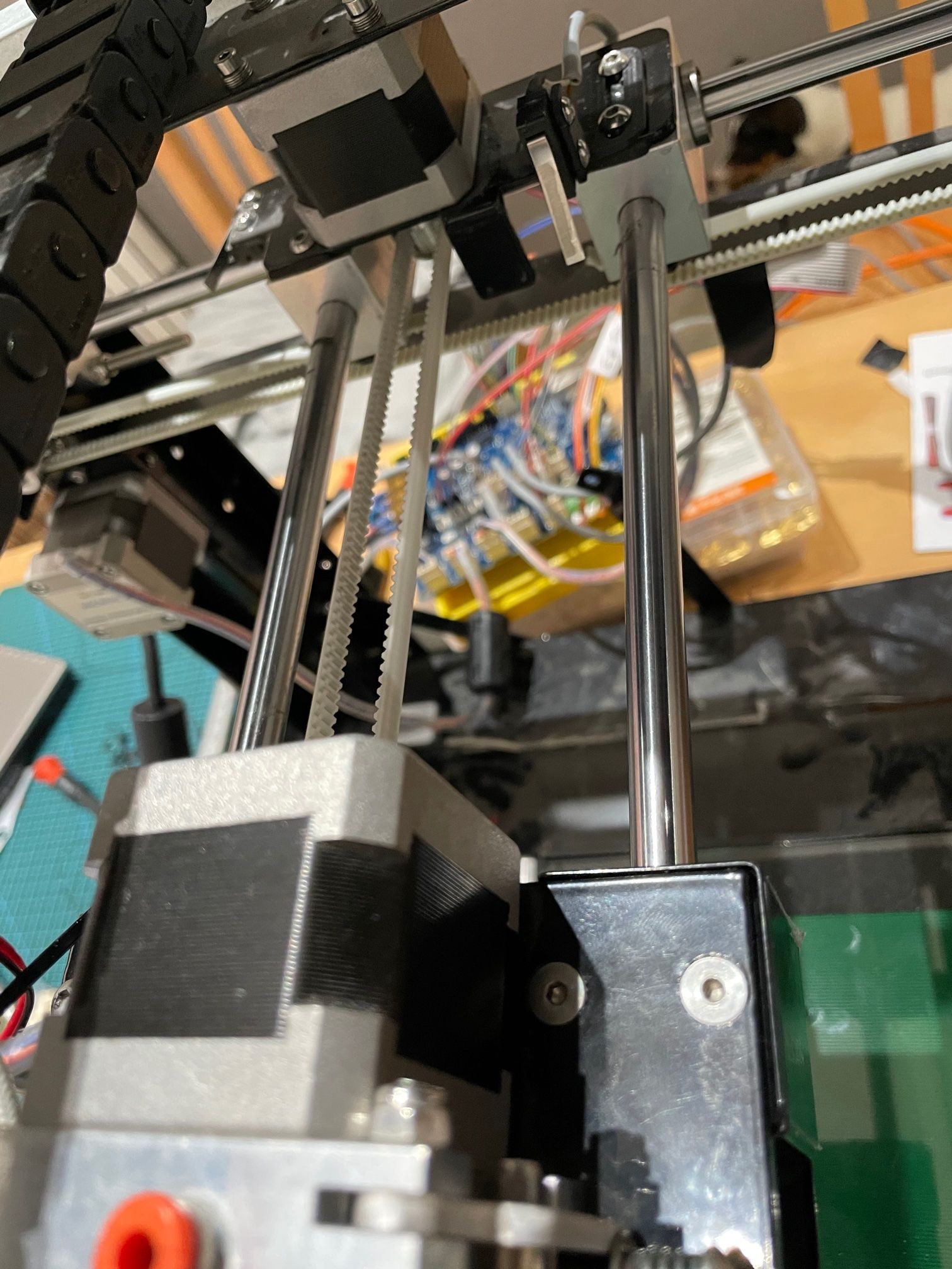
                    Y Axis - 2 belts and then a small belt to the stepper

                    IMG_7334.jpg
                    IMG_7335.jpg

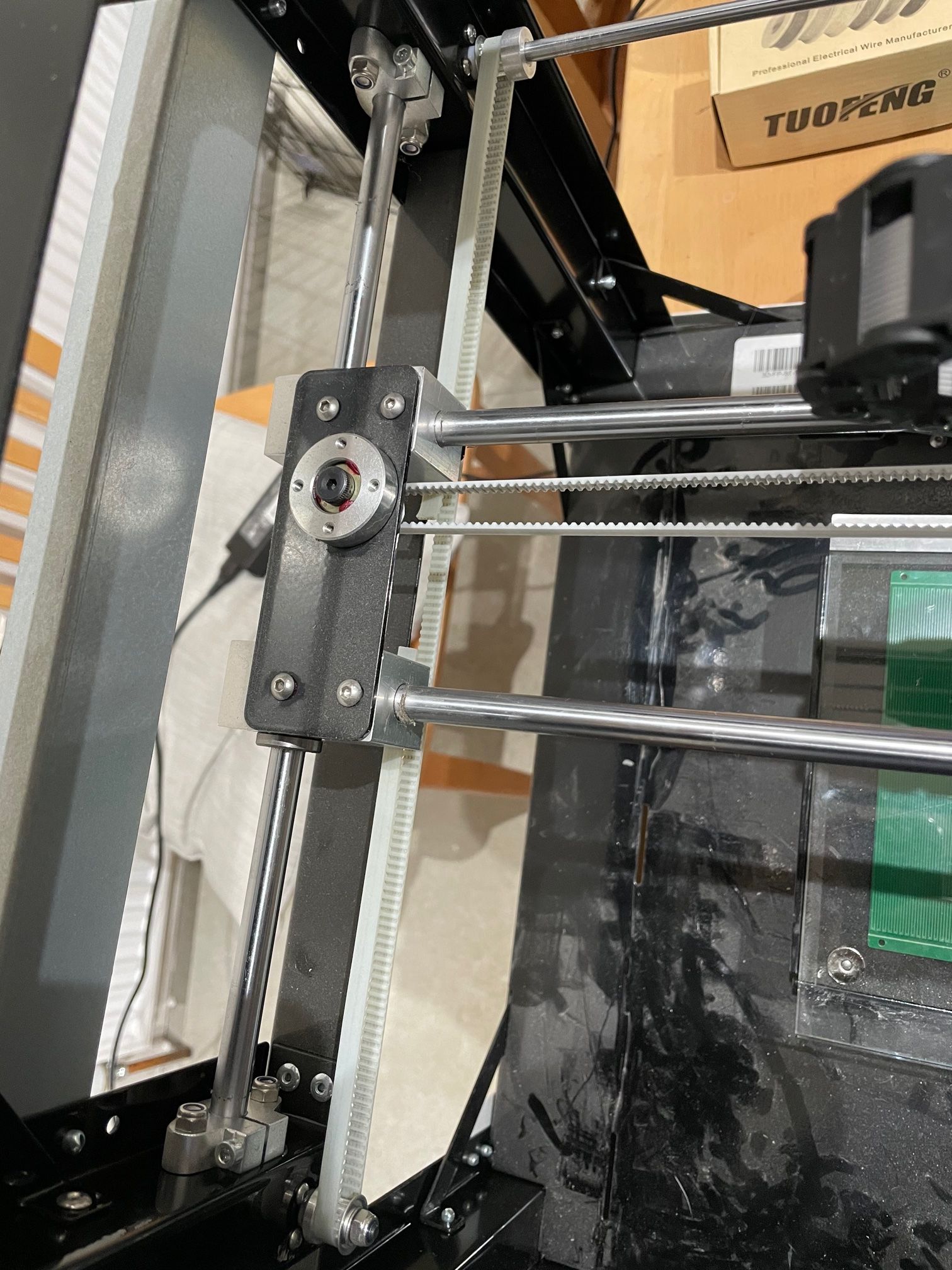
                    Z Axis - There must be a belt under the black base. I'll have to dismantle it to check.

                    IMG_7336.jpg

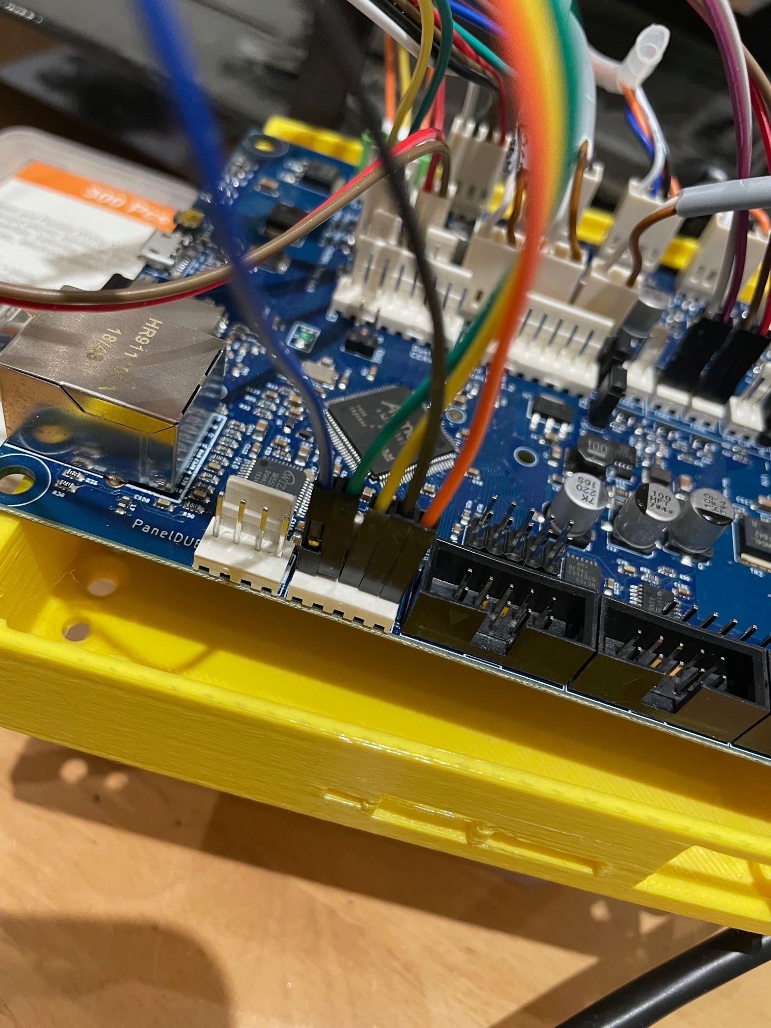
                    servo and probe wired up. Think this is right although the servo now doesn't respond. Temp wiring...

                    IMG_7337.jpg

                    1 Reply Last reply Reply Quote 0
                    • undefined
                      Veti
                      last edited by 10 Jan 2021, 19:14

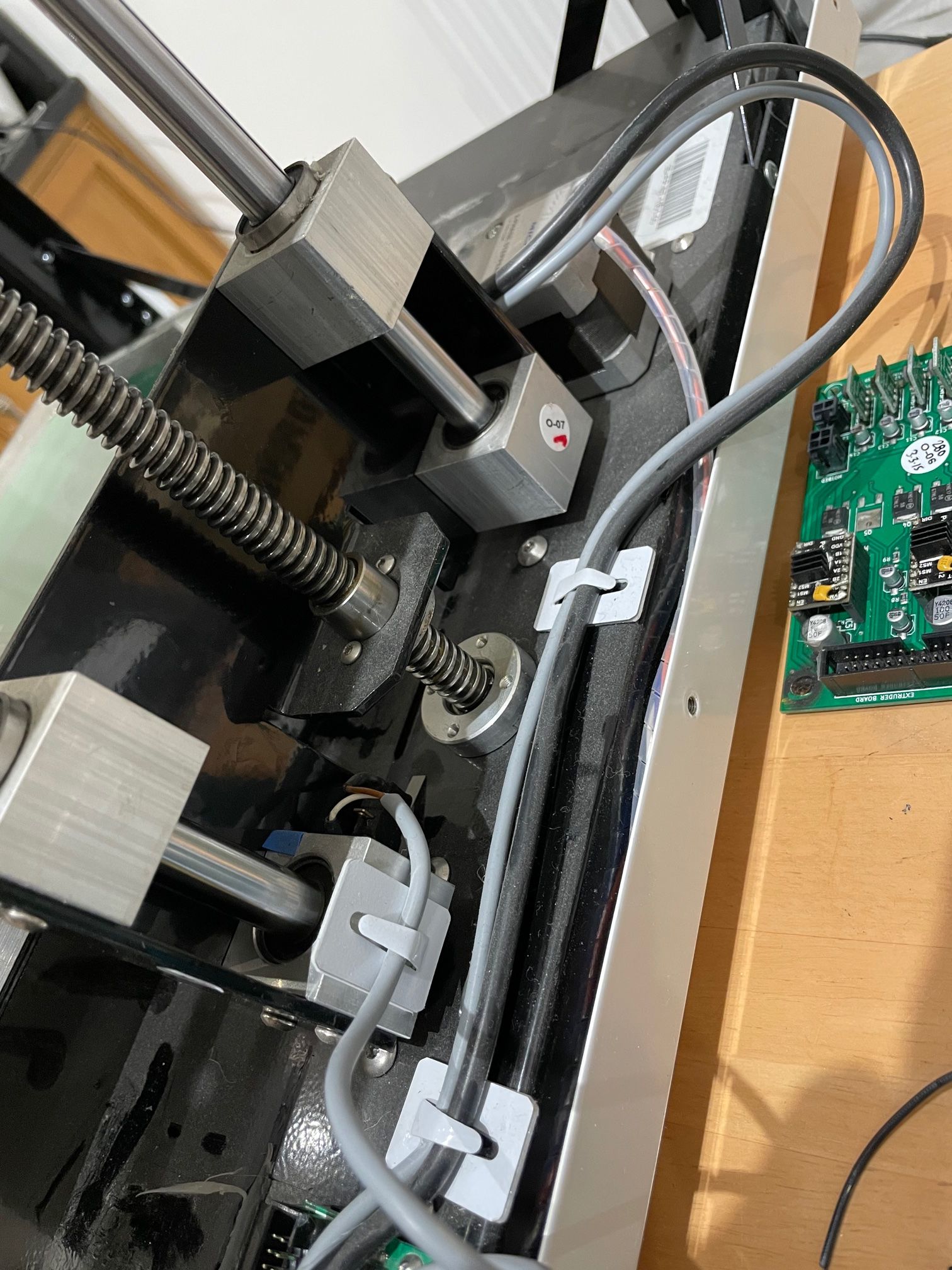
                      how is the motor connected to the lead screw? post a picture of that.

                      also you need to work out the pitch of the leadscrew.

                      undefined 1 Reply Last reply 10 Jan 2021, 19:16 Reply Quote 0
                      • undefined
                        Blacksheep99 @Veti
                        last edited by Blacksheep99 1 Oct 2021, 19:17 10 Jan 2021, 19:16

                        @Veti I believe its a belt as that would be logical but I willhave to take the base off the printer as it's under the base I believe. Seems I can't avoid it?

                        1 Reply Last reply Reply Quote 0
                        • undefined
                          Veti
                          last edited by 10 Jan 2021, 19:18

                          well if its 1:1 transmition then no

                          so work out the pitch of the leadscrew and use this to calculate the steps
                          https://blog.prusaprinters.org/calculator_3416/

                          undefined 1 Reply Last reply 10 Jan 2021, 19:23 Reply Quote 0
                          • undefined
                            Blacksheep99 @Veti
                            last edited by 10 Jan 2021, 19:23

                            @Veti said in ST3Di Modelsmart 280 - Duet Maestro repair/upgrade:

                            well if its 1:1 transmition then no

                            so work out the pitch of the leadscrew and use this to calculate the steps
                            https://blog.prusaprinters.org/calculator_3416/

                            Thanks. I would think it is. Pitch looks to be 2mm. Stepper is 1.8 degrees from the spec sheet. stepper at x16 so I think we're looking at 1600 for the Z

                            undefined 1 Reply Last reply 10 Jan 2021, 19:38 Reply Quote 0
                            • undefined
                              Blacksheep99 @Blacksheep99
                              last edited by 10 Jan 2021, 19:38

                              @Blacksheep99 said in ST3Di Modelsmart 280 - Duet Maestro repair/upgrade:

                              @Veti said in ST3Di Modelsmart 280 - Duet Maestro repair/upgrade:

                              well if its 1:1 transmition then no

                              so work out the pitch of the leadscrew and use this to calculate the steps
                              https://blog.prusaprinters.org/calculator_3416/

                              Thanks. I would think it is. Pitch looks to be 2mm. Stepper is 1.8 degrees from the spec sheet. stepper at x16 so I think we're looking at 1600 for the Z

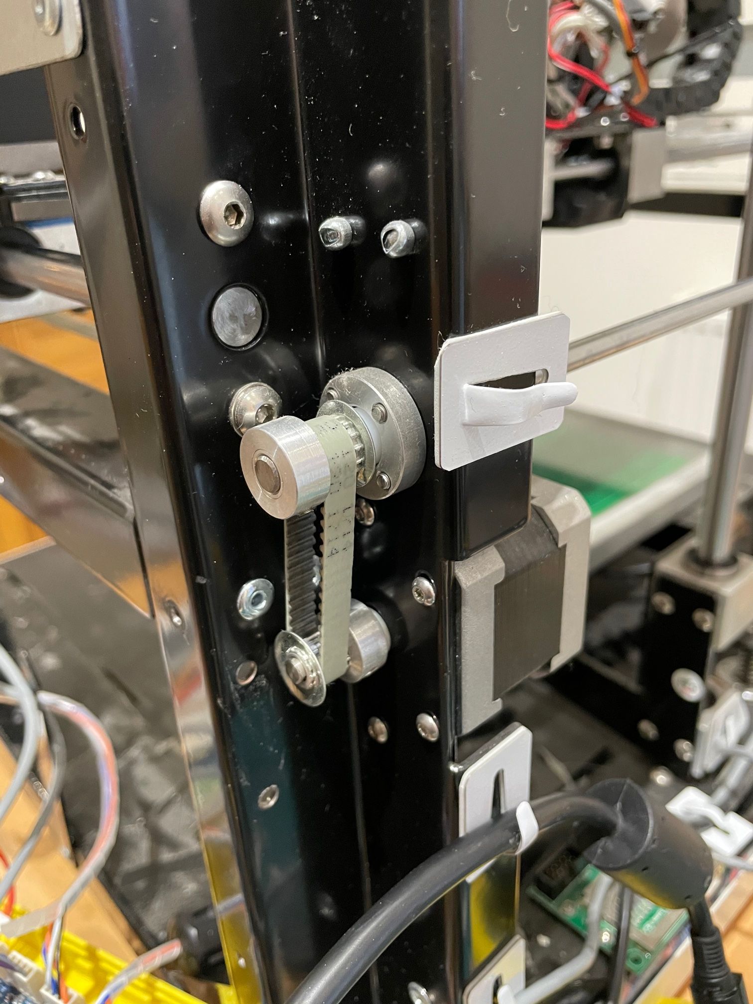
                              I take this back. I know that the build height is 150. I've tried manual Z definition and it's come at 120. If I look at the Y axis then the teeth on the two pullys the motor one is 12 teeth. Harder to count the other but looks to be 16.

                              1 Reply Last reply Reply Quote 0
                              • undefined
                                Veti
                                last edited by Veti 1 Oct 2021, 19:46 10 Jan 2021, 19:44

                                12:16 ratio with 120 would give you 160. so...

                                if its a 16:20 with 120 would give you 150.
                                you ought to open it up and count

                                undefined 1 Reply Last reply 10 Jan 2021, 19:55 Reply Quote 0
                                • undefined
                                  Blacksheep99 @Veti
                                  last edited by 10 Jan 2021, 19:55

                                  @Veti said in ST3Di Modelsmart 280 - Duet Maestro repair/upgrade:

                                  12:16 ratio with 120 would give you 160. so...

                                  if its a 16:20 with 120 would give you 150.
                                  you ought to open it up and count

                                  I will. A job for tomorrow. Thanks again, I do appreciate the help.

                                  1 Reply Last reply Reply Quote 0
                                  • undefined
                                    Blacksheep99
                                    last edited by 14 Jan 2021, 09:11

                                    Thanks to a lot of help I finally managed to get everything hooked up and in theory working. I just wanted to link to the separate thread I created for completeness.

                                    https://forum.duet3d.com/topic/20803/servo-deployed-probe-on-duet-maestro

                                    I need to tidy my wiring up, mount the board, bracket for the power cables etc.

                                    The next task is getting a successful first print.

                                    1 Reply Last reply Reply Quote 0
                                    • undefined
                                      Blacksheep99
                                      last edited by 14 Jan 2021, 16:01

                                      20mmcube.jpg

                                      Can't thank the people who have helped me enough. Still lots of work to do in terms of getting the printer calibrated properly and playing with settings but to get to this stage I'm extremely happy.

                                      It's smushing layers a little and over extruding I think. The part fan is disconnected as I need to cut the shroud that directs the air to the part so it fits around the new probe.

                                      1 Reply Last reply Reply Quote 0
                                      • undefined
                                        Phaedrux Moderator
                                        last edited by 14 Jan 2021, 19:40

                                        Not a bad first print on a conversion.

                                        Maybe give this calibration guide a go.

                                        https://duet3d.dozuki.com/Guide/Ender+3+Pro+and+Duet+Maestro+Guide+Part+4:+Calibration/40

                                        Z-Bot CoreXY Build | Thingiverse Profile

                                        1 Reply Last reply Reply Quote 0
                                        • undefined
                                          Blacksheep99
                                          last edited by 18 Jan 2021, 19:45

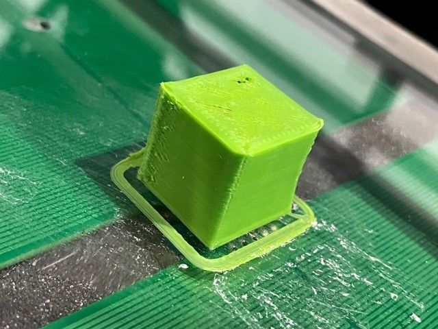
                                          I'm getting some decent test prints now. The calibration cube looks so much better and measures accurately.

                                          I'm starting to focus on the dual nozzles and try get them working together for dual colour prints. I've measured the nozzle to nozzle as 28mm. I just wondered if there were some techniques I can use to calibrate them?

                                          I'm set the printer up with centre of the bed as 0,0 and defined the centre of the tool head to align with that.

                                          1 Reply Last reply Reply Quote 0
                                          85 out of 139
                                          • First post
                                            85/139
                                            Last post
                                          Unless otherwise noted, all forum content is licensed under CC-BY-SA