CNC Screw Mapping
-
@dc42 Thanks for all the interest. I just ran it quickly doing the following...
The worst axis is X so I copied the old lookup map from WinCNC to excel, converted to mm, then created a script file... which was too big. So, I added the O option and redid it. This worked.
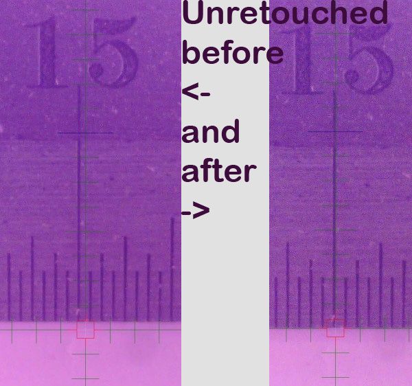
I set the cnc to 116,0 (left of table), set down my yardstick horizontally.. then I disabled screw map, went to 15",0 - a known bad area) took a screen capture of the microscope view, return to 0,0 and enabled screw map then went back to (15",0) and took another screen capture.
I hadn't tried it before - and - first try with no edits. Here's the script and the comparison photo. I know it's a lot of digits, but I'm used to inches. Probably could shrink it a little.
M801 R"X" A"XY" S116 I25.4 N36
M802 R"X" X0.00000:-0.04064:0.00000:0.06350:-0.07112:-0.10922:0.02286:-0.04318:0.00508:0.10414:-0.02794:-0.09652:-0.22352:-0.40894:-0.37846:-0.47752
M802 R"X" Y0.00000:0.01778:0.06858:0.11176:0.14732:0.18034:0.22606:0.29210:0.34544:0.36576:0.40640:0.43942:0.46228:0.51308:0.53594:0.57658
M802 R"X" O16 X-0.49784:-0.27178:-0.25908:-0.29718:-0.15240:-0.24638:-0.26162:-0.05080:-0.08636:0.01524:0.14224:-0.00508:0.05588:0.09144:0.07366:0.24130
M802 R"X" O16 Y0.60960:0.59944:0.55372:0.48514:0.40640:0.30480:0.22606:0.19304:0.15748:0.09144:-0.21082:-0.48768:-0.15748:-0.12954:-0.10160:-0.08890
M802 R"X" O32 X0.25654:0.25146:0.41656:0.78994
M802 R"X" O32 Y-0.12446:-0.09652:-0.04572:0.01270
M800 S1
Photo
-
@dc42 I've forked and updated the github repo. You can see the code changes at: https://github.com/MZachmann/RepRapFirmware/tree/v3.2-screwmap
and it forks from the 3.02-dev branch (3.2 retail).
Let me know where you'd like to go from here. Implement (pull request)? Move to M-codes? Change syntax?
The only thing I couldn't yet figure out from the code base was how to correctly have the ui update the user position when the screw map definition changes.
Mark
-
Here's a doc file describing the current implementation of screw mapping.
-
I've posted a video showing a calibration run (in X). It took about 1/2 hour to gather X and Y error terms and improved the CNC accuracy from .033" to .002".
-
Nicely done!
I just had a thought, though. Make sure your yard-stick is straight. You could be compensating for an error in the yard stick.
-
Sorry, I should have posted that. You're absolutely right.
The yardstick is one of the most expensive hand tools I own since it's so important.
-
@markz Oh!!!! That's a nice "yard stick" lol!!!
-
@bot Yeah, Starrett would probably not be happy me calling it that.
-
I also spit coffee on my laptop when I saw that price.

-
I suddenly want a yard stick like that... but I couldn't even use such a large one! My print bed is only ~11" x 11". I'll look for it's younger sibling. And possibly metric, too.
-
@bot Yeah, I wish I had a metric one - if you watch the video I spend a lot of time converting inches. Kinda dumb.
backstory - when I first realized about 10 years ago my CNC had so much error I did this measurement with a normal yardstick, couldn't believe the results (especially the Y error), so in order to root-cause I had no choice.
-
I've cleaned up the code so setting a screw map entry changes the DRO readout in real-time.
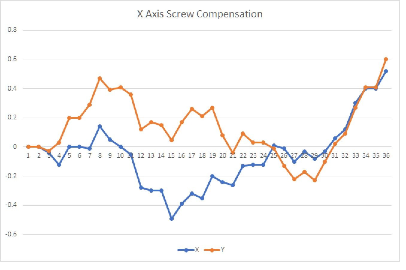
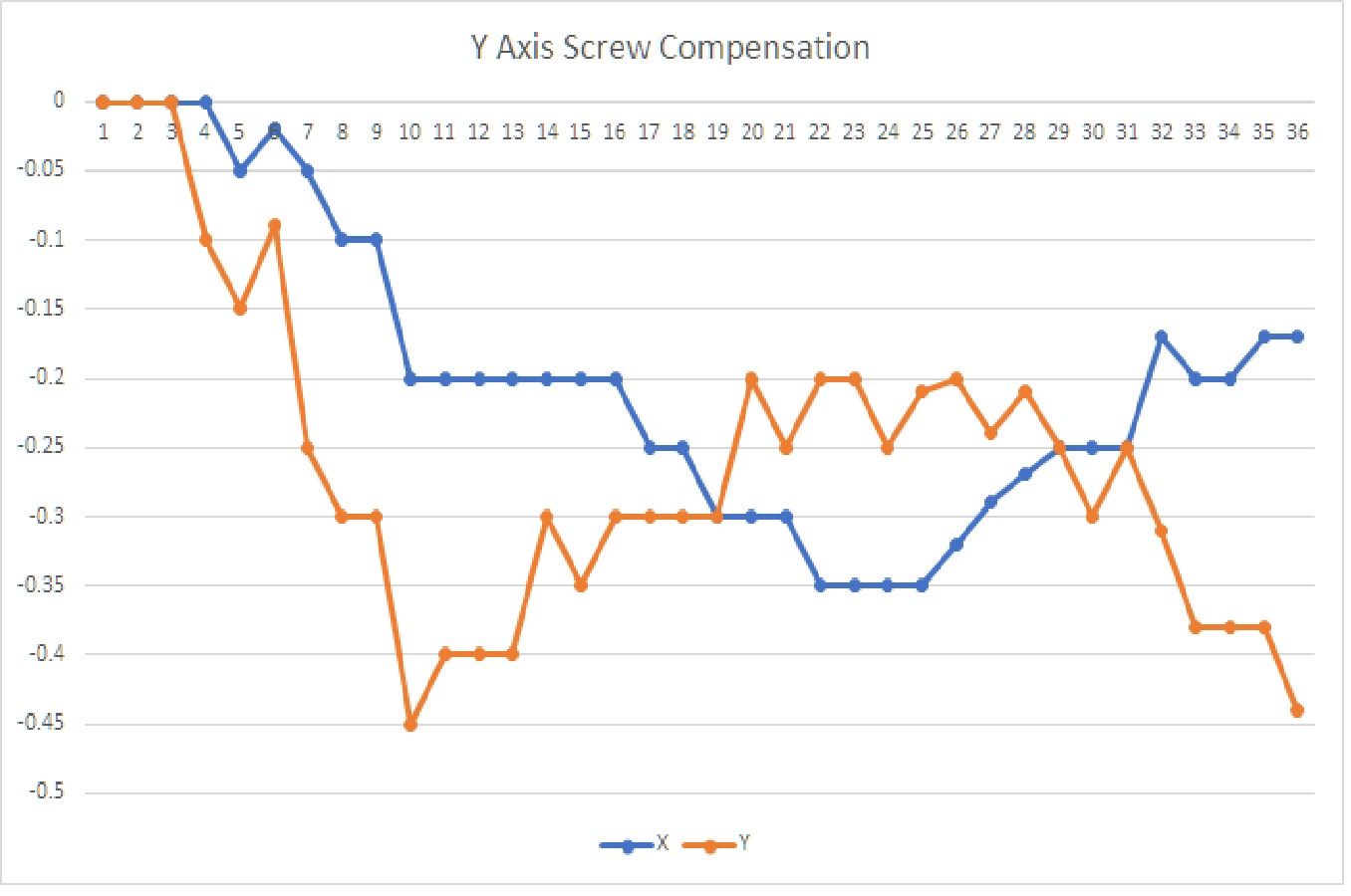
Here are a couple of plots of my CNC error curves with increment=25.4mm (1 inch). Note the 2d-ishness of the whole thing.
To put this in a worst case if I were just drilling holes the largest X error pre-compensation would be about 1.5mm (or 1/16th of an inch for US). Post-compensation error is 2*repeatability + test measurement error (~.03mm).