New(ish) Kinematics -- possible with M669?
-
Hi,
I am working on a prototype printer using a symmetric differential belt drive for a gantry moving in XYZ and the bed being stationary; see https://github.com/Apsu/Mir for
details. (It's basically h-bot for XZ and YZ with each "arm" of the H split off in Ts and put on their own side).Forward Kinematics are well defined and have been implemented in Klipper ... but I have a duet house.
The FK matrix is https://github.com/Apsu/Mir/blob/main/ForwardKinematics.png
Am I right assuming that I could configure this in RepRapFirmware doing
M669 K1 X:0.5:-0.5:0:0 Y0:0:0.5:-0.5 Z:0.25:0.25:0.25:025or am I missing something pertinent?
-
I have not checked that your M669 matrix is correct, but I believe you have the correct approach. You will need to declare a hidden U axis.
-
Thanks, I will give it a try. Will take about a week until I have a machine to break... (-:
-
@oliof
I'm wondering, how you want to solve the double rail-carrier in the middle? Do you want to mount one upside down or build a bracket around them? Where do you put the hotend(s)?
One in each corner of the crossed carrier?
Can't wait to see it running! -
@o_lampe it's just a cross gantry design like Ultimaker. Linear rails versions of effectors for that exist (CroXY, Annex Engineering K2, and others).
My personal variant "miniMir" uses CF rods and I have a preliminary design of a super small effector for a peek insulator based hotend (Merlin hotend) so that with Bowden I will likely be about 50g for the carriage plus hotend ... a bit above that with a part cooling setup. That'll limit me to filaments printable below 240C, but it should be fine for a prototype. I will start a separate thread about miniMIR when I have something to break with wrong kinematics (-:
-
@oliof said in New(ish) Kinematics -- possible with M669?:
design like Ultimaker
I haven't thought of a rod-assembly...

If I understood your design (I doubt I have") ) then the center assembly has to translate forces from one corner to the other (the split H=T bot). That's not the case for Ultimaker's design.
) then the center assembly has to translate forces from one corner to the other (the split H=T bot). That's not the case for Ultimaker's design.
Wondering, how stiff your gantry has to be, before you see a wiggling nozzle? -
Torque cancellation is covered in the upstream Mir documentation: https://github.com/Apsu/Mir#torque-cancellation -- maybe that addresses your concerns?
Other than that, we will know in a while whether the theory checks out (-: I know of two different Mir designs being built, so even if mine turns out terrible we will know whether it's due to my lack of engineering capacity quickly.
-
@oliof Interesting design! Please keep us updated with your progress. I'd love to see a video of it working. Is there forum where discussion on the design is ongoing?
I've got frame made from 30x30mm extrusion that was waiting to be made into a CoreXY, but I might have to rethink that... are there any print files for the carriages available?
Ian
-
@droftarts most of the discussion is ongoing in the 3d Printing Discord (#reprap-and-custombuilds channel). You can join here if you are interested.
There are currently several designs in the works which are discussed there, none in 3030 extrusion.
-
@droftarts I'm the creator of the Mir design, and have been delayed in finishing up the parts for my own prototype build, so I haven't shared print files yet, but I do intend to.
I'm happy to have a discussion about the design theory and build considerations here if desired, but most conversation does happen on Discord.
Is there anything about the theory of operation that isn't clear I could help clarify?
-
@Apsu @oliof Thanks for the replies. I dropped into the Discord chat to see your progress @oliof, which is looking good. It does look like an interesting kinematic design, and theory is fine! But I worry how secure the cross-arms mounting points (on the four arms) need to be, and how constrained the carriage needs to be, to counteract the torque. Any movement there presumably gets converted into a Z movement?
Ian
-
@droftarts I think it's not necessarily the case that rigidity issues with the cross-carriages result in unwanted Z motion, but rather that it results in unwanted Z force. I.e., some of the connected pieces help constrain each other, and 'activate' the differential modes of each actuator. However, if you connect the outside actuator units together in the corners, so you have effectively one square Z unit on a bunch of Z guides, the constraint is very high, and it becomes much more difficult for those stray forces to result in unwanted differential motion.
But yes, the cross-connection is a great place to focus on getting rigid as it's in a nicely balanced position to help constrain and cancel the torques.
-
It's (barely) moving!
I have the four motors setup like this:1---X---2 | | Y Y | | 0---X---3 (connected to the drives with the same numbers on the board)
0 and 2 together are X, 1 and 3 together are Y, all together are Z
to get every axis to move the right amount, I had to do the following setup
; Drives M569 P0.0 S1 ; physical drive 0.0 goes forwards M569 P0.1 S1 ; physical drive 0.1 goes forwards M569 P0.2 S1 ; physical drive 0.2 goes forwards M569 P0.3 S1 ; physical drive 0.3 goes forwards M584 X0.0 Y0.1 Z0.2 U0.3 ; set drive mapping M584 P3 M669 K0 X-1:0:1:0 Y0:-1:0:1 Z1:1:1:1 All motors move in the same direction. Could be they are moving "backwards" but it's just important that they move the same direction.
I map the motors to drive and hide every axis beyond the third (P3 -- only show 3 axes).
I had to mess with the matrix a bit to make the distances moved correct.
Apart from shitty construction, it works (-:
-
i think the diagram on the github is a bit confusing .
i think (and hope) that each half of the H bot , or "T" should be connected to the next "T" on the XY plane .
the 3d model shows it floating in the air .one issue i see is gantry leveling going to be an issue
-
@hackinistrator Correct. I didn't finish getting a more polished CAD mockup into diagram form, just was setting up the repo to support discussions I was having in realtime on Discord.
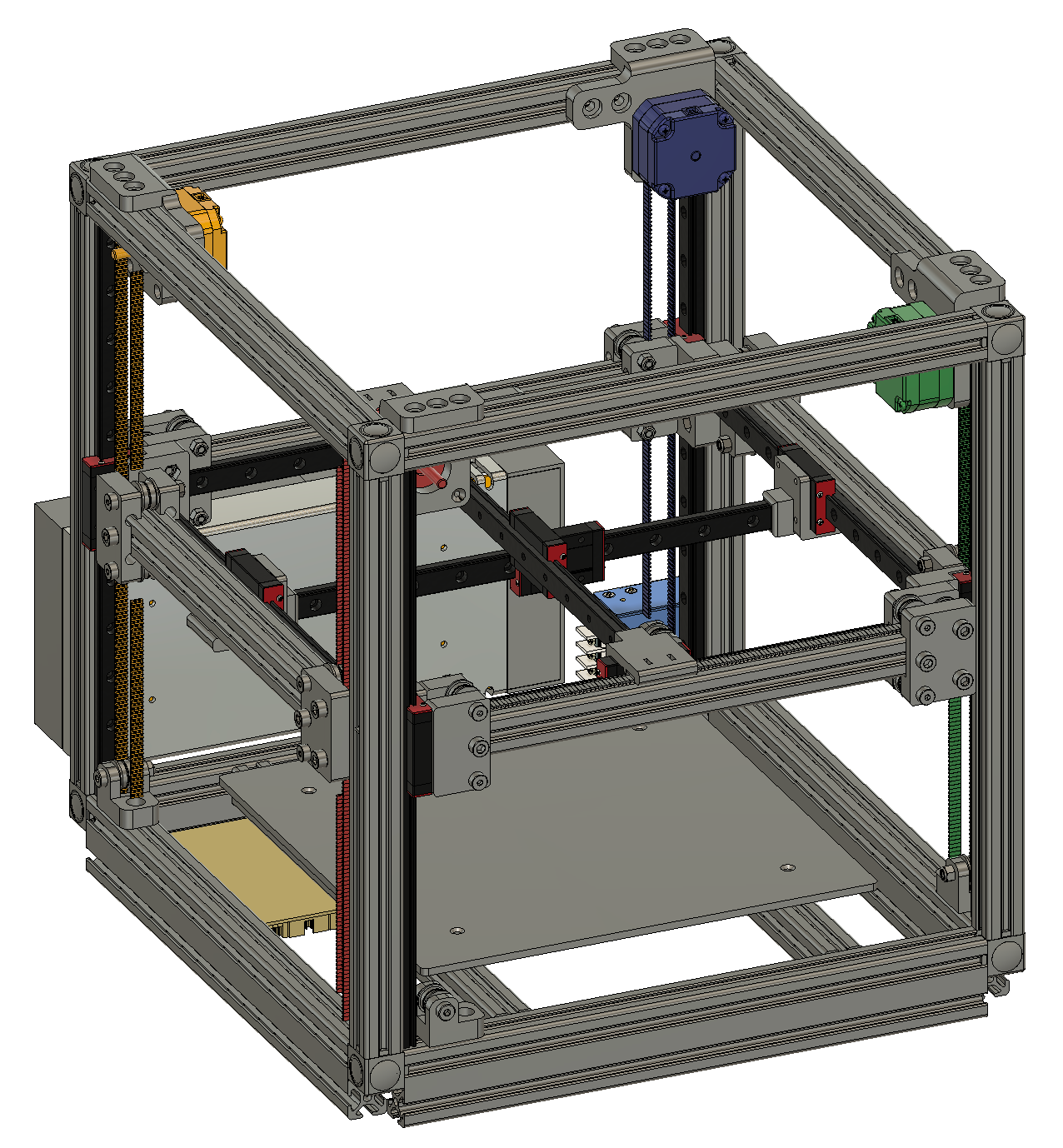
Here's a bit more complete rendering of the idea, with more of the gaps filled in and specific ideas about how to approach the interconnections and belt routing. Hope that's a little clearer.