Designing a PWM to Analog mini board for fans
-
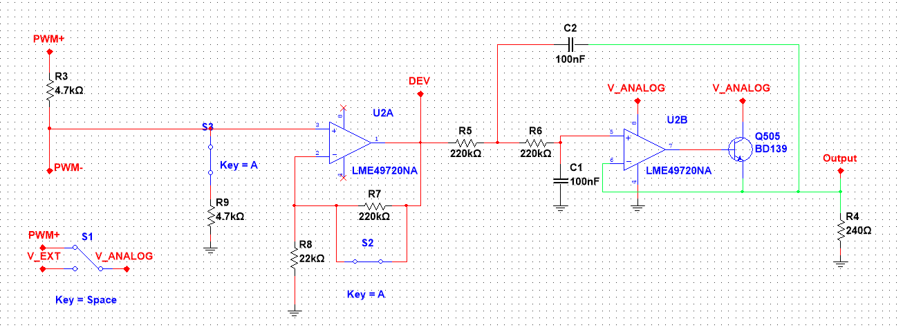
Got some simulations done for my first schematic idea:
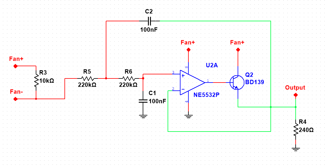
With this schematic, a 500Hz PWM frequency and a fan drawing 100mA at 24V (modelized as a 240Ohm resistor, 24V/240Ohm = 0.1A) these are the results:
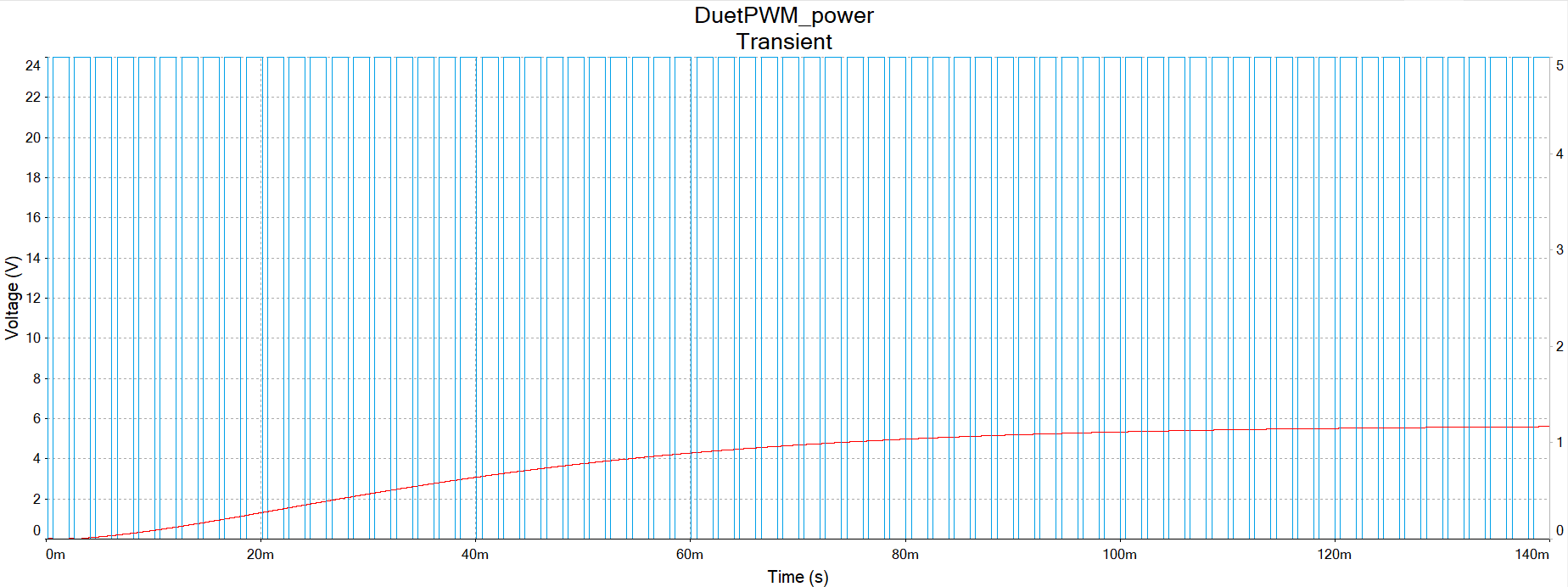
for 25% PWM:
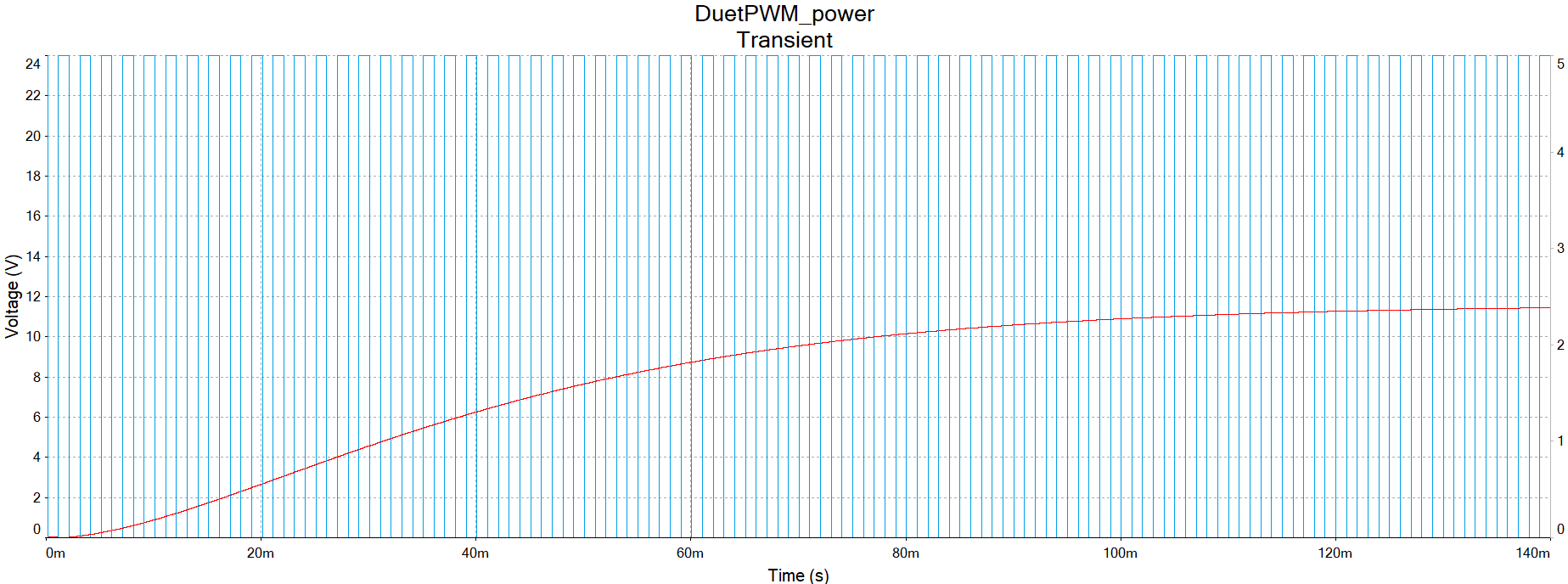
for 50% PWM:
for 75% PWM
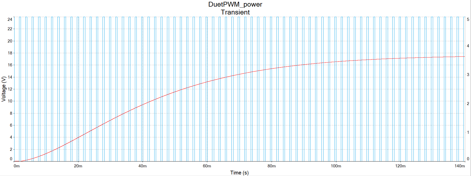
for 100% PWM (full blast)
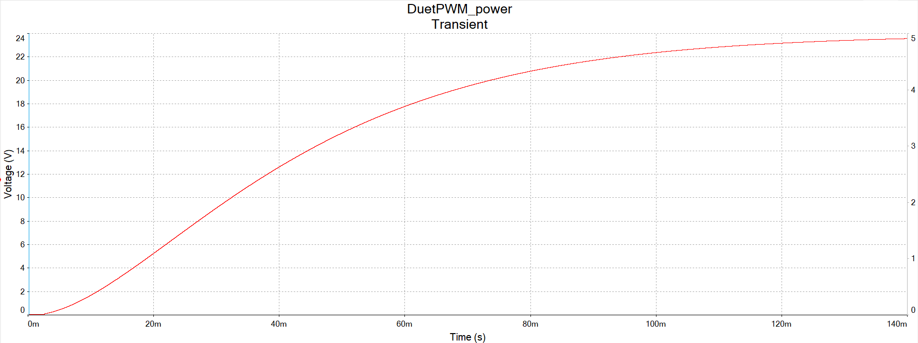
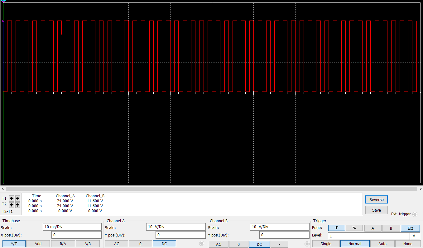
And this is a zoom-in for singal stability at 50% PWM:
As is, the analog voltage stabilizes in 150ms aprox, with a max voltage of (Vfan-Qvce) (transistor has a little voltage drop by itself), in this case 24V-0.2V -> 23.8V. Every PWM voltage will have this (-0.2V) applied, so 50% would be 11.8V instead of 12V, and so on.
Max. current depends on the transistor selected, with the caveat that the opamp has to supply enough current to the transistor base (with a typical beta about 80-100, that is, about a hundredth of the current required by the fan). Typical opamps supply about 10-20mA, so it should be good up to 1-2 amps (plenty overkill, as this is not designed for a heater but for fans!) We have to also check the maximum transistor disipation, which will happen somewhere in the middle of the ouput (PWM of 50%).
Later on I'll build it in a protoboard and check the real thing with an oscilloscope and report.
-
@achrn you schematic is ok because you are supplying 24V for a 12V fan. Mosfets have quite a high gate voltage that will substract from supply voltage, so voltage applied to the fan will not be able to reach near 24V (final voltage will depend on the mosfet used).
I'm using a BJT so I only lose about 0.2V from VCC, and a second order lowpass filter for the opamp, for an even steadier signal. BTW, did you check the dissipation power for the mosfet? It's eating quite a lot of power when regulating at 50%... I can't use a BC337 for example because it's only good up to 650mW, and I'm on the verge of it with my fans...
-
@achrn Brexit is indeed a problem right now... Maybe one small PCB + SMD components can be shipped as a postal letter?
-
@Egon-Net said in Designing a PWM to Analog mini board for fans:
Brexit is indeed a problem right now
Here in the US we are not in the EU and still will not need to pay that tax and post office fees, so the root cause may be different than what you think.
")
-
Question from a non-electrician:
The time to reach the desired Voltage takes around 90-120s, is there a way to shorten this without sacrificing precision or risking an overshoot?/Julien
-
milliseconds, not seconds!

-
And regarding max voltage, I had it wrong, the opamp model I used was too ideal and supplied more than what was supplied to him... Real max Vmax then should be Voutmax from opamp - Vbe from transistor
 I'm looking for components to minimice this.
 -
@Egon-Net said in Designing a PWM to Analog mini board for fans:
Real max Vmax then should be Voutmax from opamp - Vbe from transistor
May be worth adding a few components to achieve a more ideal requirement set. For example,
-
No significant voltage drop at max voltage (as it is with the existing PWM).
-
Decoupling pwm input voltage from output voltage. E.g. 12V in, 24V out or vice versa, or 3.3 or 5V PWM input and 12V outout.
-
Preserving the common (+) of existing PWM driven fans. (your design seems to change it to common (-)).
Other stretch goals are high efficiency (no heat when running at let's say 50%) or galvanic input isolation (opto coupler?).
Just a thought.
Overall, your idea for a PWM -> Voltage fan control is very good and much needed.
-
-
@Egon-Net said in Designing a PWM to Analog mini board for fans:
@achrn you schematic is ok because you are supplying 24V for a 12V fan. Mosfets have quite a high gate voltage that will substract from supply voltage, so voltage applied to the fan will not be able to reach near 24V (final voltage will depend on the mosfet used).
Exactly, which is why I caveated with the observation that I was using what I had to hand. The opamp output swing limits it further too - it doesn't get the gate to 24V either (even if teh PWM was coming in at 24V). Sorry, I should possibly have been more explicit that I wasn't advocating it as a great circuit (which, again, is why I might be interested in a better implementation).
There's a moderate heatsink on teh mosfet.
-
This post is deleted! -
@Egon-Net said in Designing a PWM to Analog mini board for fans:
milliseconds, not seconds!
yeah, thats more logical

-
@zapta said in Designing a PWM to Analog mini board for fans:
@Egon-Net said in Designing a PWM to Analog mini board for fans:
Real max Vmax then should be Voutmax from opamp - Vbe from transistor
May be worth adding a few components to achieve a more ideal requirement set. For example,
-
No significant voltage drop at max voltage (as it is with the existing PWM).
-
Decoupling pwm input voltage from output voltage. E.g. 12V in, 24V out or vice versa, or 3.3 or 5V PWM input and 12V outout.
-
Preserving the common (+) of existing PWM driven fans. (your design seems to change it to common (-)).
Other stretch goals are high efficiency (no heat when running at let's say 50%) or galvanic input isolation (opto coupler?).
Just a thought.
Overall, your idea for a PWM -> Voltage fan control is very good and much needed.
Hi @zapta! I'll try to answer in order:
-
The voltage drop issue is hard to resolve. I can only think in two ways for achieving it: some kind of step-up voltage converter, or going full signal filtering. The step-up will add quite a bit of complexity and would force the output voltage to be fixed (12V? 24V?), and I want to avoid a full signal filter, because it would use quite big inductors, that end up being big, heavy and expensive. I've been looking at opamps/BJT combos that allow me to stay within 0.5V of VCC, and I think I can live with it. I will have a look at existing integrated PWM to Analog too (I think analog devices makes such an IC), because yes, it would be nice to go up to the supply rail.
-
Decoupling is more or less done already. I can further add a voltage divisor and add later gain in the filter so you could use any voltage combo, even things like 3.3v -> 24V
-
I think I haven't understand you correctly. You use the PWM+ wire from Duet. In the base design you use both PWM+ and PWM- (they are called Fan+ and Fan-). Duet's do the PWM on the ground side (PWM-), so you can use any voltage for the fan.
Regarding the other comments, heat is unavoidable once you give up filtering in full signal, because there must be some analog component that does the regulation (we are not switching voltages) but since we are dealing with currents <100mA, it should stay well under 1W. And IMHO adding galvanic isolation is out of the question for the complexity it would add when we are just dealing with fans...
Thanks for your comments, that's really what I need to help me think out of the box! You never know what one's maybe missing!
-
-
@achrn said in Designing a PWM to Analog mini board for fans:
@Egon-Net said in Designing a PWM to Analog mini board for fans:
@achrn you schematic is ok because you are supplying 24V for a 12V fan. Mosfets have quite a high gate voltage that will substract from supply voltage, so voltage applied to the fan will not be able to reach near 24V (final voltage will depend on the mosfet used).
Exactly, which is why I caveated with the observation that I was using what I had to hand. The opamp output swing limits it further too - it doesn't get the gate to 24V either (even if teh PWM was coming in at 24V). Sorry, I should possibly have been more explicit that I wasn't advocating it as a great circuit (which, again, is why I might be interested in a better implementation).
There's a moderate heatsink on teh mosfet.
I've just tested TLV9352 as the opamp and TIP41A as the BJT, and it leaves me at 0.5V from supply voltage. It might be quite difficult to get better than that with this kind of schematic...
-
Ill get a hand full if Brexit is not going to make shipment to Germany crazy expensive. Are you heading for SMD or through hole components?
This is not only super convenient for Fans but i will use this analog voltage to control some LEDs with an Arduino Nano
Custom ANET A8
Custom Delta: D-PATCH (Delta Printer with Automatic Tool CHanging) https://forum.duet3d.com/topic/16082/d-patch?_=1596131234754All I do here is under this license: CC BY-NC-SA
-
Thanks @taconite! I'm going for smd, but not crazy difficult to solder (just 0805, soic8...) Depending on how many people want some boards and their ability to solder smd, I can offer sending boards already populated with smd components.
Regarding controlling leds, why don't you directly feed PWM to the leds? If your PWM frequency is high enough, you can't see the flicker at all...
-
@taconite also remember the current limits... I don't think this kind of circuit is good for more than ...200mA? The BJT will dissipate quite a bit of power by itself at moderate currents, but it depends too on supply voltage (5V would draw much less power).
-
I thing I'll leave and option to feed the opamp/transistor with an external power, using something like that:
so you can jumper select the power supply.
Thoughts?
-
Ok, I had a spin at the schematic. That would the plan:
INPUTS:
PWM+
PWM-
GND
Optional V_EXTJUMPERS:
V_ANALOG (PMW+ or V_EXT)
HALVE_IN (shorted=yes)
SCALE_OUT (shorted = no)OUTPUT
Analog V_OUTEXPLAINING
Duets use PWM+ as V_FAN, PWM- as pwm'd ground.
With HALVE_IN open, SCALE_OUT closed, VOUT follows PWM input up to V_FAN-0.6V. Rise time is about 140ms.You can use a external step up converted (1€ in Aliexpress for a 28V 2A max) connected to V_EXT and then select jumper V_ANALOG to V_EXT and get max fan voltage. With just one step up you can feed many fans.
You can also connect an external (arduino?) PWM voltage to PWM+ with any voltage and any power supply to V_EXT, and output would follow (3.3V, 5V, 12V...) You cannot use a PWM+ voltage greater than V_EXT. If you set HALVE_IN short, input is automatically halved, so you can use a 24V PWM+ with a 12V V_EXT, for example.
And last, if you short jumper SCALE_OUT, PWM+ voltage will be ignored and V_OUT will be PWM % of V_ANALOG.
This is the schematic for reference:
It would use a dual smd opamp (TLV9352, 0.7-1€ ) some resistors/capacitors (smd 0805, ~cents), a through-hole mid-power BJT (like BD139, ~0.5€) and some jumper pins, plus board (less than 1€) and shipping costs for everything. The transistor must be heatsinked for any significant current.
Does it sound interesting? Would you get some of this boards?
-
@Egon-Net said in Designing a PWM to Analog mini board for fans:
I think I haven't understand you correctly. You use the PWM+ wire from Duet. In the base design you use both PWM+ and PWM- (they are called Fan+ and Fan-). Duet's do the PWM on the ground side (PWM-), so you can use any voltage for the fan.
What I mean is that the duet uses a low side transistor and common (+) connection, with this design, the transistor is on the high side and the fans have common (-) connection.
-
@Egon-Net said in Designing a PWM to Analog mini board for fans:
VOUT follows PWM input up to V_FAN-0.6V
How did you calculate this? Supply voltage - 0.6V VBE for Q505?
Do you assume that the U2B output can go all the way to the V_ANALOG voltage? This is not the case with most op amps. Did you verify that this is indeed the case?
Changing the design to use a non emitter follower configuration may eliminate the need for the OPAMP to go all they way to the rail voltage. Can be a PNP on the high side or NPN on the low side (or P or N channel respectively if you prefer mosfets).
(I am not an EE so please take it with a grain of salt).