Pressure Advance: Discussion for Future Development
-
@dc42 said in Pressure Advance: Discussion for Future Development:
I'm sorry, I don't have time to look at improving PA until I've implemented input shaping. But I've bookmarked this thread so that I can return to it. Pressure advance smoothing is something I was already thinking about.
Thanks for the reply. It's good to know that it is on the radar.
I'm wondering if one of my suggestions: not allowing PA to change the print head acceleration, might be developmentally cheap enough to try in a beta release?
I still believe that when PA reduces print head acceleration, it could be adding to the issue of mismatched extrusion rate.
-
@zapta said in Pressure Advance: Discussion for Future Development:
I run a small experiment, printing calicat at 50mm/s with different PA values while watching the retraction graph on the stepper analyzer.
Is this the stepper analyzer you are using? https://forum.duet3d.com/topic/21312/low-cost-public-domain-stepper-analyzer-season-2
I'm curious if I could at least get a detailed step output from the Duet Maestro to track the extruder dur PA moves.
-
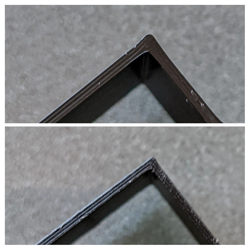
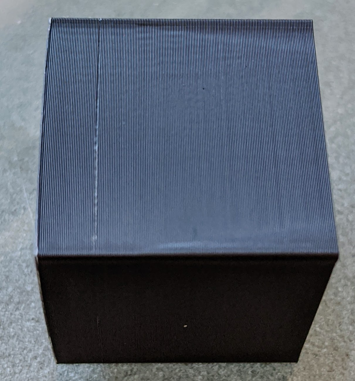
I did a test cube, running PA only on perimeters, to see if in the simplest case I could improve sharp corner geometry and/or the seam.
Print parameters:
- 0.4mm nozzle
- 0.15mm layers
- 50mm/s perimeters
- PA varied by layer from 0.0 to 1.5
- Max Accel (mm/sec^2): X: 4000.0, Y: 4000.0, Z: 400.0, E: 10000.0
- Max jerk (mm/sec): X: 16.0, Y: 16.0, Z: 4.0, E: 5.0
- Print accel (perimeters): 1200 mm/s^2
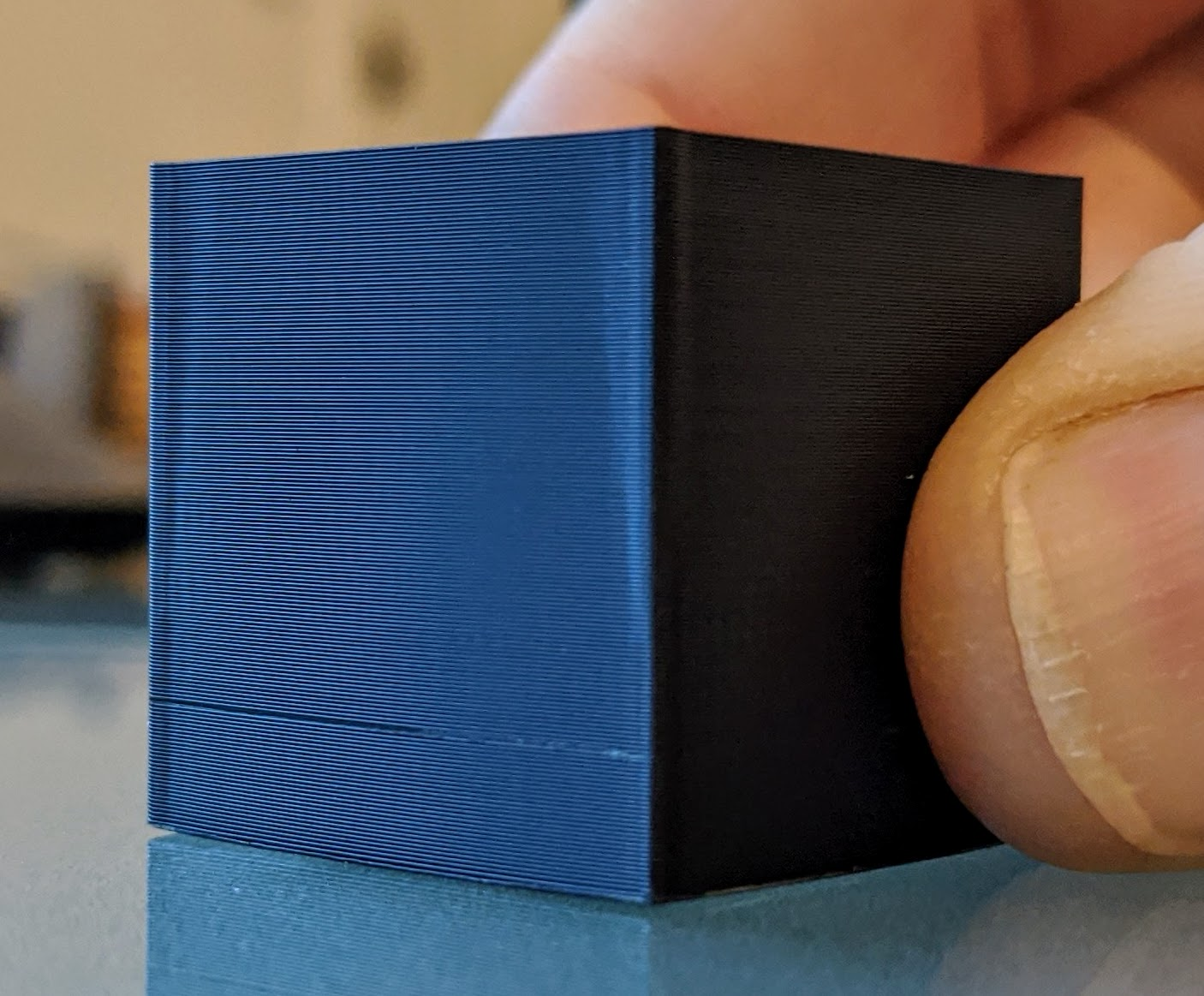
In these photos, hopefully you can see what I can in person. Everything looks best with PA nearest zero. There is a corner bulge, but it is crisp and only affects the area very near the corner. Once PA values rise, the geometry deviation grows away from the corner (especially in the decel region), without actually reducing the corner bulge. The 22mm cube measures 22.10mm near the bottom (low PA), and measures 22.26mm at higher PA values.


I'm a little baffled at how PA seems to provide no benefit in this test. But, IMO, the corner deviation growing away from the corner has to do with the print head accel being reduced at higher PA values, and lends some credibility to my suggestion of allowing an option to run the print head "untethered" by PA.
Thoughts?
-
@CCS86 said in Pressure Advance: Discussion for Future Development:
I'm a little baffled at how PA seems to provide no benefit in this test. But, IMO, the corner deviation growing away from the corner has to do with the print head accel being reduced at higher PA values, and lends some credibility to my suggestion of allowing an option to run the print head "untethered" by PA.
Thoughts?
Generally you want to do pa tests with only 1 or 2 perimeters and no infill. Also you want the seem in the middle of a side if your slicer will allow that. If you slicer won't allow for it, print a cylinder of a large enough diameter that the print head hits the requested print speed.
Imo, based on the last picture you have some serious ringing you need to address before you worry about PA.
for reference this is what i have on my railcore running a direct drive E3d V6.
M201 X4500 Y4500 Z250 E1500       ; Accelerations (mm/s^2)
M203 X24000 Y24000 Z1500 E3600    ; Maximum speeds (mm/min)
M566 X1500 Y1500 Z120 E1500       ; Maximum jerk speeds mm/minute
Important settings from my various ideamaker pla profiles. 0.4mm nozzle, 0.4mm extrusion width, 0.2mm layer height
Vel Accel Jerk PA flowrate Temperature 50 600 1500 0.11 86.2 200 50 480 1200 0.125 86.2 200 50 360 900 0.14 86.2 200 50 240 600 0.155 86.2 200 50 120 300 0.17 86.2 200 100 3600 1500 0.08 85.8 205 100 2880 1200 0.08 85.8 205 100 2160 900 0.08 85.8 205 100 1440 600 0.08 85.8 205 100 720 300 0.08 85.8 205 150 4500 1500 0.08 86.0 220 150 3600 1200 0.08 86.0 220 150 2700 900 0.08 86.0 220 150 1800 600 0.08 86.0 220 150 900 300 0.08 86.0 220 -
The ringing is a separate thing altogether. I had bumped my XY jerk up a good bit for this PA test to mitigate some of the need for PA. The photos exaggerate the ringing a bit too.
How are your flow rates the same for velocities ranging from 50 - 150 mm/s, with fixed layer height and extrusion width?
-
@CCS86 said in Pressure Advance: Discussion for Future Development:
How are your flow rates the same for velocities ranging from 50 - 150 mm/s, with fixed layer height and extrusion width?
See the temperature column.
-
This is getting off topic, but temperature has nothing to do with flow rate ( [layer height] x [extrusion width] x [velocity] ).
-
@CCS86 said in Pressure Advance: Discussion for Future Development:
This is getting off topic, but temperature has nothing to do with flow rate ( [layer height] x [extrusion width] x [velocity] ).
I think you are confusing volumetric flow rate with the flow rate adjustment parameter. the flow rate adjustment parameter is Ideamakers terminology for what other slicers call Extrusion multiplier. I maybe should have added a % after.
If volumetric flow rate or temperature is changed, you usually need to adjust the flow rate parameter/Extrusion multiplier, to deal with the increased or decreased pressure in the heat affected zone.
-
@CCS86 said in Pressure Advance: Discussion for Future Development:
I'm curious if I could at least get a detailed step output from the Duet Maestro to track the extruder dur PA moves.
It depends what kind of report rate you want. It does measure the stepper position, including micro stepping 100k times a second but it aggregates and displays it.
Looking at the schematic of the Maestro, each driver has a step and direction inputs. If those are actually used (you can try or ask dc42), than you can connect a logic analyzer (you can find them for cheap), record as much as you want and then analyze the recording with some script.
-
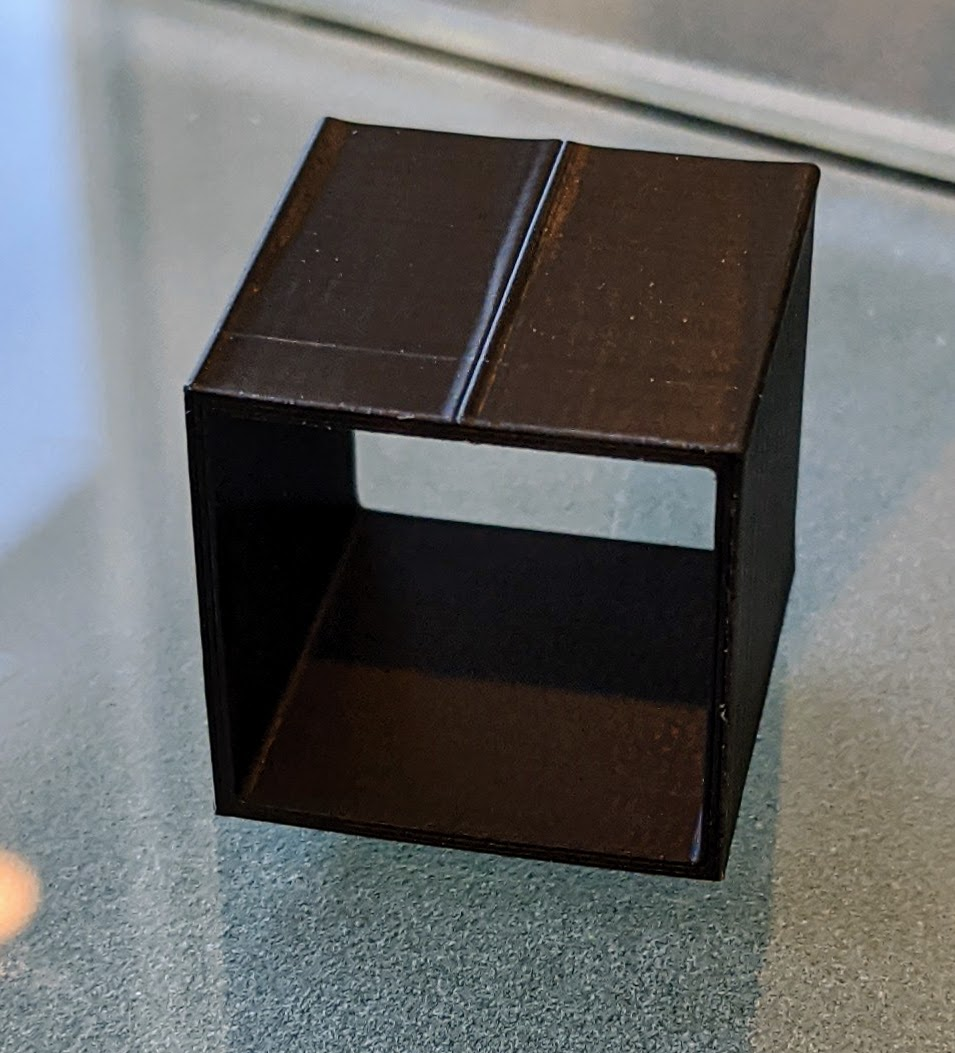
Results look the same with XY accel/jerk in a better state of tune. PA=0 for the first 5mm of print, than increasing layer-by-layer from 0 to 1.5:
-
I wanted to give this thread a bump, since it has been a long time.
Hopefully @dc42 will get the time for PA development in the near future with IS provisionally released.
I'd love to beta test some of the ideas I put forward in this thread, and I now have one of @zapta 's stepper analyzers hooked up for some further visual analysis of extruder motion.
-
Here is another data point. A Diamond 3 or 5 colour hot end needs a PA value of around 0.5. My experimental 6 input hot end requires a PA value of less than 0.1. It's currently questionable if any PA is necessary with this hot end but certainly 0.2 is far too much. The major difference between a Diamond hot end and my version is that the Diamond has a straight section at the end of each filament path of 3mm at 0 4mm diameter. After the filaments have been combined, there is a further straight section of 2mm at 0 4mn diameter. So each filament path has a section at the end of 5mm in length at 0.4mm diameter. With my hot end, the filament paths are 1.8mm diameter all the way to the nozzle. The hole at the end of a standard E3D V6 nozzle is generally lass than 1mm (depending on diameter). The filament paths on my hot end are longer than a Diamond so it has a larger volume of molten plastic. I'll leave it to others to form their own conclusions as to the cause of pressure build up (I know what mine are).