RRF3 - Dual Extruder Calibration / Tool and Nozzle Offset
-
Hey guys,
at the moment I am working on a dual extruder tool together with @CR3D . The first prototype of the tool is working right now - the tool is comparable to a Startasys or Ultimaker 3 Nozzle-Lifting assembly but the actuation is done by a servo. At the moment I am stresstesting and performing little improvements.
I want to use / built a firmware-integrated nozzle-offset-routine for both hotends - in this I want to calibrate the x, y and z offset of both nozzles.
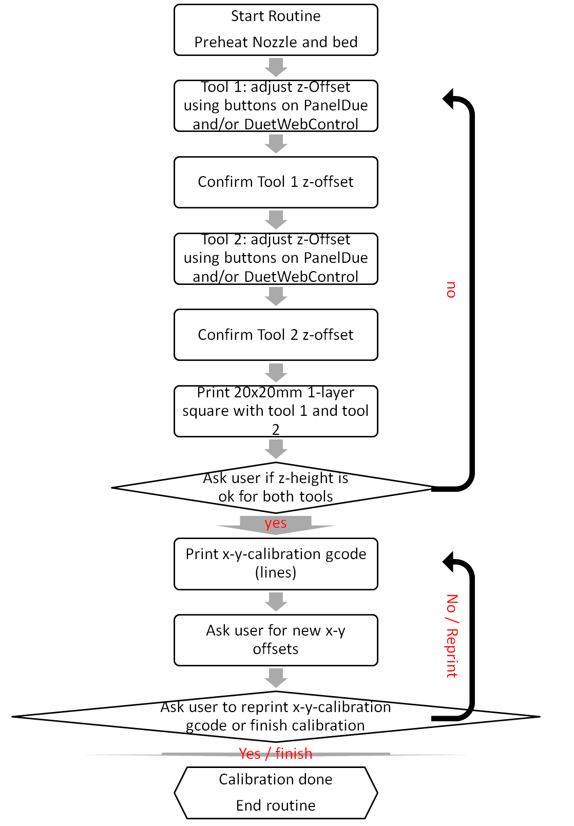
To calibrate the offset of both nozzles I want to use a routine similar to the one by BCN3D and Craftbot.
At first I want to move the nozzle - close to the bed using a PanelDue and/or webInterface.
After that is done for both tools a simple z-offset test print (i.e. 20x20mm 1-layer square) shall be printed.
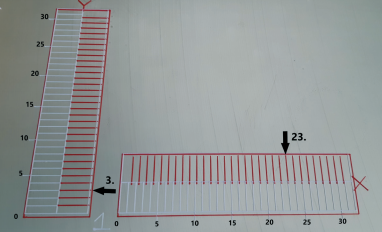
Afterwards the user shall be promted if the z offset is ok. If yes: the routine continous. If no: the routine goes back to z-offset adjustment.The same is done for x-y-offest - just with using "line" extursions like the ones on the picutre:
I tried to built a flow chart of the things I want to do:
Writing the gcode and doing basic configuration is not a problem for me.
My main questions are:- How can I safe the new Offsets to the config.override?
- How can I create "buttons/popups" in DWC and PanelDue as an "interface" for the calibration routine"
- Is this even possible within RRF3.x or is something similare integrated?
Have a nice day,
Max -
-
config-override.g currently store workspace offsets G10 L2 but it looks like it does not store tool offsets (G10 L1). possibly a feature request for the firmware wishlist.
-
M291 can be used to prompt the user to jog an axis... I am not sure this is the best method though because those printed vernier scales can be read directly and the number used to update the offset.
-
not yet!
Rather than this method, for now at least I would adapt it for the user to adjust Z (using babystepping if required) and then use the baby stepping value to adjust the tool offset manually (following your instructions, step by step)
Then once both tools are done, move on to using the printed verniers to capture the XY offset and once gain have the use update the offset command for that tool.
You could still have that file as a separate gcode file, called from config.g, so your user does not need to modify config.g directly.
-
-
@MacNite said in RRF3 - Dual Extruder Calibration / Tool and Nozzle Offset:
Hey guys,
at the moment I am working on a dual extruder tool together with @CR3D . The first prototype of the tool is working right now - the tool is comparable to a Startasys or Ultimaker 3 Nozzle-Lifting assembly but the actuation is done by a servo. At the moment I am stresstesting and performing little improvements.
While I can't answer your question, I am intrigued by your lifing head system. Could you maybe start a new thread that gives some details and some pictures ?
-
Hey guys,
thank you for the response.
The baby-stepping idea looks quite good. I may try that - I had the idea yesterday to incorporate something as implented in the Prusa MK3 firmware for z-adjusting.
I'll test that and try to set it up...somehow.
@jens55
Unfortunately I am not able to share the project progress at the moment. But we have the prototype working and do stress testing now. So it will be not to long until we release further information.
You can find more information here:https://www.facebook.com/cr3d.official
https://www.cr3d.de/Greets
Max -
I have started to built some gcode....I did not have the time to test it and some lines are just place-holders (either I did not know the exact code or I just could not find a proper solution.
I assume the calibration of the z-offset would work like that. But I encounterd some problems.1: Is it possible to check wether filament is loaded? Option A: check if filament is loaded through the filament Load buttons in DWC. B: The Filament Runout Sensor is triggerd. (refering to
2: Is it possible to ad markers in some form? I.E. in Line 23 and 39. After printing the z-calibration test print the user shall be asked if he / she is satisfied with the results. If yes then --> start xy-calibration. If no: Return to line 23 and re-start z-calibration.
3: The general concept of the xy calibration I assume is clear. There even is a reference I found in the duet wiki :
https://duet3d.dozuki.com/Wiki/ConfiguringMultipleIndependentXcarriagesCartesian#Section_Calibration
Is it possible to "built / generate" some kind of input fields in DWC / PanelDue so the user can add the values....or choose a value from multiple pre-defined ones?Maybe @dc42 may provide some Input on this? I've read there were some plans on "expanding" the M291 functionality but I assume this is not done right now?
; add tool1offset.g and tool2offset.g to config.g with M98 P"tool1offset.g" M98 P"tool2offset.g"
; built z-calibration gcode - 20x20 square

M291 P"This will reset all previous defined tool offsets to the default values. Do you want to continue?" R"Calibration of Tool Offsets" S3
G28
M104 S200 T1					; Active & Standby Temperature for Tool 1 200°C
M104 S200 T2					; Active Standby Temperature for Tool 2 200°C
M140 S65					; Set Bed Temperature to 65°C
???? G10 L2 P1 X-10 Y0 Z0			; set Tool 1 offsets to default values
???? G10 L2 P2 X10 Y0 Z0			; set Tool 1 offsets to default values
G1 Z5
	; chek if Filament is loaded in tool 1
if FILAMENT_LOADED_TOOL1 == TRUE Then
ELSE
T1
M701 S"PLA"
	; chek if Filament is loaded in tool 2
if FILAMENT_LOADED_TOOL2 == TRUE Then
ELSE
T2
M701 S"PLA"
	; start z-calibration routine
;##marker-mc-markface
M291 P"Put a piece of Paper on the built plate" R"Calibration of z-Position" S2
T1
M291 P"Move the Bed up using the buttons until the paper slightly graps on the nozzle" R"Calibration of z-Position- Tool 1" S3 X0 Y0 Z1
M28 tool1offset.g
???? G10 L2 P1 Z{axes[3].position}		; set z-offset of Tool1 to value from last calibration
M29
T2
M291 P"Move the Bed up using the buttons until the paper slightly graps on the nozzle" R"Calibration of z-Position- Tool 2" S3 X0 Y0 Z1
M28 tool2offset.g
???? G10 L2 P2 Z{axes[3].position}		; set z-offset of Tool2 to value from last calibration
M29
M291 P"Remove Piece of Paper" R"Calibration of z-Position" S2
	; start test print for z-calibratoin
M98"z_test_print.g"				; Print z-calibration lines
	; ask user if he is satisfied
;If-Statement to ask user if z-offset is fine or z-calibration has to re-run, for rerun re_turn to ##marker-mc-markface
	;start xy offset calibration
; to come....