Manual Bed Levelling & Mesh Levelling on a corexy printer?
-
@fcwilt thank you that's a massive help, will try that out tomorrow and let you know how it goes
-
Setting up the Manual Bed Leveling Assistant (MBLA)
Measured the printer today and have located all the screws relative to Home position 0,0 which is Front Left on my CoreXY.
I've listed the screws in config.g in order Rear Left, Rear Right, Front Right & Front Left; Configuration file for Duet WiFi (firmware version 3)
; executed by the firmware on start-up
;
; generated by RepRapFirmware Configuration Tool v3.1.4 on Wed Nov 04 2020 17:51:25 GMT+0000 (Greenwich Mean Time); General preferences
G90 ; send absolute coordinates...
M83 ; ...but relative extruder moves
M550 P"Eniac40" ; set printer name
M669 K1 ; select CoreXY mode
M671 X-34:413:413:-34 Y434:434:13:13 P0.5 ; 1screwRL(-34,434), 2screwRR(413,434), 3screwFR(413,13), 4screwFL(-34,13), thread pitch 0.5mm; Network
M552 S1 ; enable network
M586 P0 S1 ; enable HTTP
M586 P1 S0 ; disable FTP
M586 P2 S0 ; disable Telnet; Drives
M569 P0 S1 ; physical drive 0 goes forwards
M569 P1 S1 ; physical drive 1 goes forwards
M569 P2 S0 ; physical drive 2 goes backwards
M569 P3 S1 ; physical drive 3 goes forwards
M584 X0 Y1 Z2 E3 ; set drive mapping
M350 X16 Y16 Z16 E16 I1 ; configure microstepping with interpolation
M92 X80.24 Y80.24 Z399.44 E412.00 ; set steps per mm
M566 X900.00 Y900.00 Z60.00 E3000.00 ; set maximum instantaneous speed changes (mm/min)
M203 X15000.00 Y15000.00 Z720.00 E15000.00 ; set maximum speeds (mm/min)
M201 X1000.00 Y1000.00 Z100.00 E5000.00 ; set accelerations (mm/s^2)
M906 X1700 Y1700 Z1700 E680 I30 ; set motor currents (mA) and motor idle factor in per cent
M84 S30 ; Set idle timeout; Axis Limits
M208 X0 Y0 Z0 S1 ; set axis minima
M208 X380 Y423 Z405 S0 ; set axis maxima; Endstops
M574 X1 S1 P"!xstop" ; configure active-high endstop for low end on X via pin !xstop
M574 Y1 S1 P"!ystop" ; configure active-high endstop for low end on Y via pin !ystop
M574 Z1 S1 P"!zstop" ; configure active-high endstop for low end on Z via pin !zstop; Z-Probe
M558 P0 H2 F120 T15000 ; disable Z probe but set dive height, probe speed and travel speed
M557 X15:215 Y15:195 S20 ; define mesh grid; Heaters
M308 S0 P"bedtemp" Y"thermistor" T100000 B4092 ; configure sensor 0 as thermistor on pin bedtemp
M950 H0 C"bedheat" T0 ; create bed heater output on bedheat and map it to sensor 0
M307 H0 A84.5 C94.6 D0.7 S1.00 V11.9 B0 ; PID heated bed
M140 H0 ; map heated bed to heater 0
M143 H0 S80 ; set temperature limit for heater 0 to 80C
M308 S1 P"e0temp" Y"thermistor" T100000 B4725 C7.06e-8 ; configure sensor 1 as thermistor on pin e0temp
M950 H1 C"e0heat" T1 ; create nozzle heater output on e0heat and map it to sensor 1
M307 H1 A298.1 C175.7 D3.8 S1.00 V11.8 B0 ; PID hotend heater; Fans
M950 F0 C"fan0" Q500 ; create fan 0 on pin fan0 and set its frequency
M106 P0 S0 H-1 ; set fan 0 value. Thermostatic control is turned off
M950 F1 C"fan1" Q500 ; create fan 1 on pin fan1 and set its frequency
M106 P1 S1 H1 T45 ; set fan 1 value. Thermostatic control is turned on
M950 F2 C"fan2" Q500 ; create fan 2 on pin fan2 and set its frequency
M106 P2 S1 H1 T180 ; set fan 2 value. Thermostatic control is turned on; Tools
M563 P0 D0 H1 F0 ; define tool 0
G10 P0 X0 Y0 Z0 ; set tool 0 axis offsets
G10 P0 R0 S0 ; set initial tool 0 active and standby temperatures to 0C; Custom settings are not defined
; Miscellaneous
M575 P1 S1 B57600 ; enable support for PanelDue
M591 D0 P2 C"e0_stop" S1 ; filament monitor connected to E0_stop
T0 ; select first toolThen in bed.g i listed the probe points in the same order RL, RR, FR, FL. I also added M561 to clear any previous settings, & deactivated M401 & M402 as i dont have a z probe and want to use the 4 manual levelling screws to adjust the bed hieght, is that the right thing to do?
; bed.g
; called to perform automatic bed compensation via G32
;
; generated by RepRapFirmware Configuration Tool v3.1.4 on Wed Nov 04 2020 17:51:25 GMT+0000 (Greenwich Mean Time)
; G29 ; probe the bed and enable compensationM561 ; clear any bed transform
G28 ; home
; M401 ; deploy Z probe (disabled)
G30 P0 X87 Y314 Z-99999 ; probe near an adjusting screw RL
G30 P1 X293 Y314 Z-99999 ; probe near an adjusting screw RR
G30 P2 X293 Y110 Z-99999 ; probe near an adjusting screw FR
G30 P3 X87 Y110 Z-99999 S4 ; probe near an adjusting screw FL and report adjustments needed
; M402 ; retract probe (disabled)Does that look like a useable Config.g & Bed.g or have i missed anything?
Nathan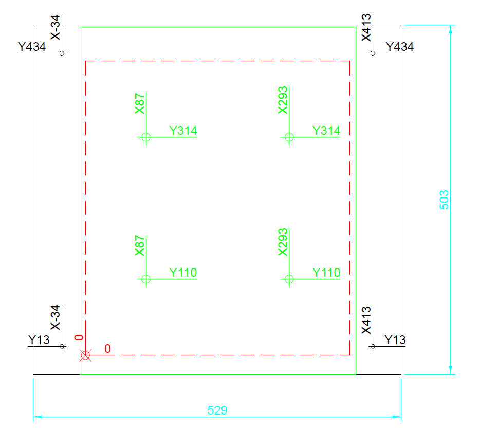
-
Hi,
Are those probe points as close to the adjustment screws as you can get?
Frederick
Printers: a E3D MS/TC setup and a RatRig Hybrid. Using Duet 3 hardware running 3.4.6
-
@fcwilt using those positions gives me a large level area covering roughly 3/5ths of the glass and is big enough for 99% of what I print. This means I don't have to run a mesh levelling routine to compensate for any uneveness.
If I level at the extremes then only the outer front and rear edges are printable and the centre section is too high and I'd have to use mesh compensation all the time when I just want to use it for very occasional prints -
@fcwilt Just a thought, could I set the following as a macro and use it for regular sized prints that don't need mesh bed compensation
; macro to perform manual bed levelling assistance
;
; G29 ; probe the bed and enable compensation; Preheat PLA
M140 S60;
M104 S180 T0;
M561 ; clear any bed transform
G28 ; home
; M401 ; deploy Z probe (disabled)
G30 P0 X87 Y314 Z-99999 ; probe near an adjusting screw RL
G30 P1 X293 Y314 Z-99999 ; probe near an adjusting screw RR
G30 P2 X293 Y110 Z-99999 ; probe near an adjusting screw FR
G30 P3 X87 Y110 Z-99999 S4 ; probe near an adjusting screw FL and report adjustments needed
; M402 ; retract probe (disabled)Then have my bed.g file, that i'd activate with G32, with a different set of probe co-ordinates closer to the edge, and then follow that up with mesh bed compensation?
-
Hi,
Have you done anything with the conditional gcode feature of v3 firmware?
I use it to control things like choosing between mesh compensation being enabled or not at the start of a print.
Since v3 doesn't currently have variables I used dummy fan names as a text variable that I could set and test.
If you would like I could give you the details.
Frederick
-
@fcwilt No I haven't read up on those
I have the code ready and will try it tomorrow morning but worried I'm going to damage my printer if i mess this code up or it doesn't do what I think it'll do
How i want it to operate is run G32,
the print head will move to P0 and the bed will hit the mechanical end stop and stop at "0"
then i adjust the screw on the bed corner to allow a sheet of paper to just pass between the bed and the nozzle, then tell the printer to move to the next point and so on till all four corners are levelIs this what will happen with this code?
; bed.g
; called to perform automatic bed compensation via G32
;
; generated by RepRapFirmware Configuration Tool v3.1.4 on Wed Nov 04 2020 17:51:25 GMT+0000 (Greenwich Mean Time)
; G29 ; probe the bed and enable compensationM561 ; clear any bed transform
G28 ; home
; M401 ; deploy Z probe (disabled)
G30 P0 X87 Y314 Z-99999 ; probe near an adjusting screw RL
G30 P1 X293 Y314 Z-99999 ; probe near an adjusting screw RR
G30 P2 X293 Y110 Z-99999 ; probe near an adjusting screw FR
G30 P3 X87 Y110 Z-99999 S4 ; probe near an adjusting screw FL and report adjustments needed
; M402 ; retract probe (disabled) -
@natty15d said in Manual Bed Levelling & Mesh Levelling on a corexy printer?:
@fcwilt No I haven't read up on those
I have the code ready and will try it tomorrow morning but worried I'm going to damage my printer if i mess this code up or it doesn't do what I think it'll do
How i want it to operate is run G32,
the print head will move to P0 and the bed will hit the mechanical end stop and stop at "0"
then i adjust the screw on the bed corner to allow a sheet of paper to just pass between the bed and the nozzle, then tell the printer to move to the next point and so on till all four corners are levelIs this what will happen with this code?
; bed.g
; called to perform automatic bed compensation via G32
;
; generated by RepRapFirmware Configuration Tool v3.1.4 on Wed Nov 04 2020 17:51:25 GMT+0000 (Greenwich Mean Time)
; G29 ; probe the bed and enable compensationM561 ; clear any bed transform
G28 ; home
; M401 ; deploy Z probe (disabled)
G30 P0 X87 Y314 Z-99999 ; probe near an adjusting screw RL
G30 P1 X293 Y314 Z-99999 ; probe near an adjusting screw RR
G30 P2 X293 Y110 Z-99999 ; probe near an adjusting screw FR
G30 P3 X87 Y110 Z-99999 S4 ; probe near an adjusting screw FL and report adjustments needed
; M402 ; retract probe (disabled)No it doesn't work that way.
It will probe all for points first and then calculate the required adjustments and display them.
At least that is how it works with an actual Z probe.
Have you considered getting one for your printer?
Frederick
-
@fcwilt Thought about it but only need it for prints that take up the entire bed which for me is rare, and it'll add extra weight the carriage.
Came across a post by @Phaedrux who did something very close to what i want to do so I've altered it to this
; macro to perform manual bed levelling assistance to the centre of the bed only for regular prints
; Preheat PLA
M140 S60;
M104 S180 T0;
M561 ; clear any bed transform
G28 X ; home X
G28 Y ; home Y
G28 Z ; home Z; Move nozzle to leveling points and prompt user to level bed at each point
M291 P"Nozzle will now move to the 4 leveling points RL, RR, FR & FL." S1 T2; Move to Rear Left leveling point P0
G1 Z5 ; move to z5 for travel
G1 X87 Y314 ; Move to rear left corner
G1 Z0 ; move to z0 to level the bedM400
M291 P"Adjust RL using a piece of paper, when set click Confirm to go to RR" R"CONFIRM" S2 Z0; Move to Rear Right leveling point P1
G1 Z5 ; move to z5 for travel
G1 X293 Y314 ; Move to rear right corner
G1 Z0 ; move to z0 to level the bedM400
M291 P"Adjust RR using a piece of paper, when set click Confirm to go to FR" R"CONFIRM" S2 Z0; Move to Front Right leveling point P2
G1 Z5 ; move to z5 for travel
G1 X293 Y110 ; Move to front right corner
G1 Z0 ; move to z0 to level the bedM400
M291 P"Adjust FR using a piece of paper, when set click Confirm to go to FL" R"CONFIRM" S2 Z0; Move to Front Left leveling point P3
G1 Z5 ; move to z5 for travel
G1 X87 Y110 ; Move to front left corner
G1 Z0 ; move to z0 to level the bedM400
M291 P"Adjust FL using a piece of paper, when set click Confirm" R"CONFIRM" S2 Z0; Move Z
G1 Z50 ; Drop bed to z50 for nozzle clearanceM291 P"The bed has been mechanically leveled" S2
-
@natty15d said in Manual Bed Levelling & Mesh Levelling on a corexy printer?:
@fcwilt Thought about it but only need it for prints that take up the entire bed which for me is rare, and it'll add extra weight the carriage.
Came across a post by @Phaedrux who did something very close to what i want to do so I've altered it to this
That might work. You may have to run it more than once.
The actual Manual Bed Leveling Assistant (which works best with a Z probe) takes into account how each adjustment screw will interact with the others and the suggested adjustments reflect that.
Frederick
-
@fcwilt Just created a second one to level the entire bed, then ill follow that up with Mesh Bed Compensation. That's going to be another head scratcher LOL
; macro to perform manual bed levelling assistance to the Entire bed for large prints
; Preheat PLA
M140 S60;
M104 S180 T0;
M561 ; clear any bed transform
G28 X ; home X
G28 Y ; home Y
G28 Z ; home Z; Move nozzle to leveling points and prompt user to level bed at each point
M291 P"Nozzle will now move to the 4 leveling points RL, RR, FR & FL." S1 T2; Move to Rear Left leveling point P0
G1 Z5 ; move to z5 for travel
G1 X40 Y372 ; Move to rear left corner
G1 Z0 ; move to z0 to level the bedM400
M291 P"Adjust RL using a piece of paper, when set click Confirm to go to RR" R"CONFIRM" S2 Z0; Move to Rear Right leveling point P1
G1 Z5 ; move to z5 for travel
G1 X340 Y372 ; Move to rear right corner
G1 Z0 ; move to z0 to level the bedM400
M291 P"Adjust RR using a piece of paper, when set click Confirm to go to FR" R"CONFIRM" S2 Z0; Move to Front Right leveling point P2
G1 Z5 ; move to z5 for travel
G1 X340 Y52 ; Move to front right corner
G1 Z0 ; move to z0 to level the bedM400
M291 P"Adjust FR using a piece of paper, when set click Confirm to go to FL" R"CONFIRM" S2 Z0; Move to Front Left leveling point P3
G1 Z5 ; move to z5 for travel
G1 X40 Y52 ; Move to front left corner
G1 Z0 ; move to z0 to level the bedM400
M291 P"Adjust FL using a piece of paper, when set click Confirm" R"CONFIRM" S2 Z0; Move Z
G1 Z50 ; Drop bed to z50 for nozzle clearanceM291 P"The entire bed has been mechanically leveled, now perform Mesh Bed Compensation" S2
-
That macro worked well for me because I can easily visually see how close the nozzle is to the bed so a tiny adjustment to the screw is needed and it stays put for a long time. I have it do two passes of the 3 screws and it's enough for me. YMMV
-
-
Very glad to hear you got it working.
If you get tired to doing it manually a 8mm inductive sensor like mine only weighs 43 grams. I would imagine your existing extruder assembly weighs a good deal more than that.
Frederick
-
@Phaedrux @fcwilt I used Mesh Bed Compensation for the first time and it worked perfectly. What id like to know is now that I've switched the printer off, when i turn it back on is the MBC still on or do i have activate it with G29 S1.
Is there a way to see if the MBC is active or inactive on the paneldue or web interface?Thanks
Nathan -
@natty15d said in Manual Bed Levelling & Mesh Levelling on a corexy printer?:
@Phaedrux @fcwilt I used Mesh Bed Compensation for the first time and it worked perfectly. What id like to know is now that I've switched the printer off, when i turn it back on is the MBC still on or do i have activate it with G29 S1.
Is there a way to see if the MBC is active or inactive on the paneldue or web interface?The height map you created with G29 or G29 S0 is saved and can be re-loaded at any time with G29 S1.
But you do have to re-load it. I do it at the start of each print and unload it at the end of each print as it really serves no purpose when you are not printing.
All slicers that I have used have a way to execute user created gcode.
My approach is to have a macro called print_begin.g and another called print_end.g.
In the slicer I have M98 P"print_begin.g" and M98 P"print_end.g" in the appropriate places the slicer provides for entering user code.
The macros do everything required to prepare to start a print or finish up at the end of a print.
Frederick
-
-
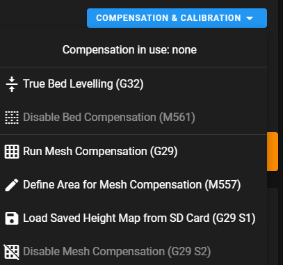
Hi,
I forgot to include this screen shot showing where you can check the state of mesh compensation.
This is from the DWC for v3.2.2
Frederick
-
@fcwilt That's perfect thankyou again
")