Revolver-Filament-Change
-
----Filament change running with stepper motor?----
Hey,
I wanna install a filament changer in a revolver style.
I use 2 stepper motors in a row, so that I can force the filament to the direct drive extruder and back.
So my question is, if anybody knows how to make a g code which turns the filament-change-motor in the right position.
as example:
retract t0 and t1 50mm- turn filament change motor 50 steps - force new filament inside 50mm with t0 and t2.Please help me -- Would be lovely.
KR to all -
Is a revolver design similar to the Prusa MMU?
-
@barbarossa-cologne Calculate how many steps you would need to turn the revolver to the angle you need. convert the steps to distance in mm and then issue a G1 command to move how ever many mm's you need for the rotation.
-
this is the top view.....
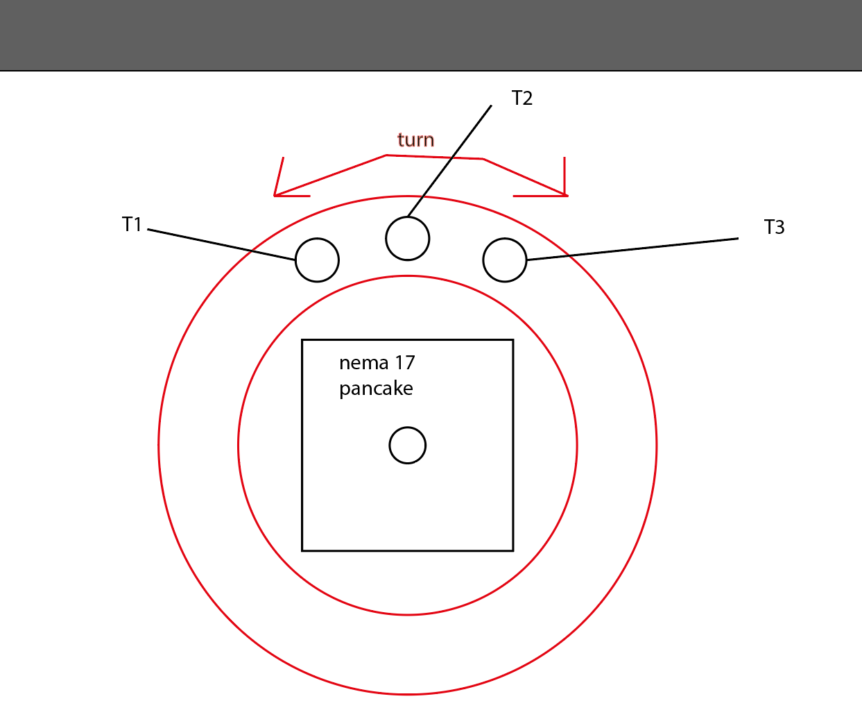
T1,T2 and T3 are the incoming holes for the tube.
Under this circle is the tube for the direct drive extruder.
Circle and the 3 holes are movable.
I hope this describtion is understandable.Thanks!!!!
-
@timcurtis67 already did the calculation. I just need to configurate the g code.
then I put in the exact numbers. In this case move from hole to hole are 25 steps.And there is the question, if I have to work with a endstop or not.
-
@barbarossa-cologne
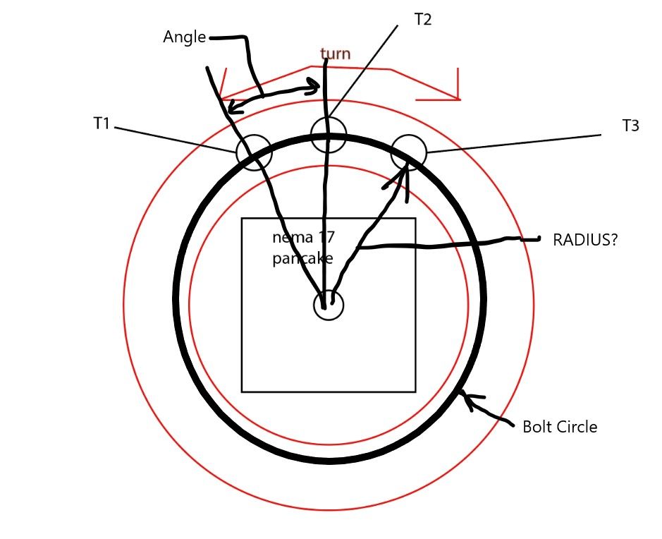
You would want to have some form of and endstop to home to so you know where the cylinder holes are located.A few questions to figure out your calculation.
What is the bolt circle or radius of the hole pattern from the center of the stepper motor?
What is the angle between each hole?
What is the steps per mm configured for this stepper now?
-
See attached image.
-
Sorry for the late reply and thanks for the help.
So I have an angle of 18deg... which are 10 steps. I changed the angle to work with easier numbers.I made a little trick..
I just say (even it´s not true) that steps/mm are 10 AND resulted to it I just say that the that the holes are 1mm away from each other.Steps/mm: 10 = 18deg angle
Angle to change Filament: 18deg
Angle between T1 hole and endstop= 18degI think I don´t have problems with the calculation.
What I need is more the G-codes procedure, which I think is something like:
Pause --> retract 50mm --> turn 18deg / 10 steps --> push filament back inside.thank you so much!
-
@barbarossa-cologne Don't forget that will be 10 FULL steps for 18 degrees of motor movement. So if you use 16X micro stepping, you'll need to send (10x16=) 160 steps.
-
@barbarossa-cologne said in Revolver-Filament-Change:
Sorry for the late reply and thanks for the help.
So I have an angle of 18deg... which are 10 steps. I changed the angle to work with easier numbers.I made a little trick..
I just say (even it´s not true) that steps/mm are 10 AND resulted to it I just say that the that the holes are 1mm away from each other.Steps/mm: 10 = 18deg angle
Angle to change Filament: 18deg
Angle between T1 hole and endstop= 18degI think I don´t have problems with the calculation.
What I need is more the G-codes procedure, which I think is something like:
Pause --> retract 50mm --> turn 18deg / 10 steps --> push filament back inside.thank you so much!
SO are you saying that the part revolves 18 degrees when you apply 10 steps? Are you including the micro stepping?
What is your M350 set at for this axis?
Also what is your M92 set at for this axis?Both should be in your config file.
10 steps is not very much. I would bump up your micro stepping (M350) to give you a higher steps per mm.
Anyway using your numbers your movement command would be this, G1 U1.0 F100. This would move the axis 1mm (18 degrees) in the positive direction. This also assumes you are calling the rotary axis "U"
You will have to set up which way is positive and negative in you config file.
So a G1 U1.0 would get you to the first hole, G1 U2.0 would get you to the second hole, G1 U3.0 would get you to the third hole.
As long as you stay in G90 then which ever U position you call up will take you to that hole. Make sense to you?
-
@deckingman
ok thanks to remember me! -
@timcurtis67
yes 18 deg by 10 full steps so in generell with microsteps this are 160 steps like @deckingman said.
sorry for that.
So If I understand it correctly, M350 will be 160 steps per mm?
And M92 is 160 steps --> telling the boarg how much steps to turn from hole to hole?Direction of turning --> I know about this.
")
So I define the rovelver motor as U-Axis on the second expansion board (I know how to define the right board etc) and give the information about steps/mm --> I think I undersood (I hope so).
``As long as you stay in G90 then which ever U position you call up will take you to that hole. Make sense to you?´´ --> yes. make sense.
I think only missing is the difinition for the pause while the filament should change, right?
thanks a lot!!!!!!!!!!!
-
@barbarossa-cologne said in Revolver-Filament-Change:
@timcurtis67
yes 18 deg by 10 full steps so in generell with microsteps this are 160 steps like @deckingman said.
sorry for that.
So If I understand it correctly, M350 will be 160 steps per mm?
And M92 is 160 steps --> telling the boarg how much steps to turn from hole to hole?Direction of turning --> I know about this.
So I define the rovelver motor as U-Axis on the second expansion board (I know how to define the right board etc) and give the information about steps/mm --> I think I undersood (I hope so).
``As long as you stay in G90 then which ever U position you call up will take you to that hole. Make sense to you?´´ --> yes. make sense.
I think only missing is the difinition for the pause while the filament should change, right?
thanks a lot!!!!!!!!!!!
Not quite. M350 is the micro-stepping mode so you'd want to set that at 16x. For M92 you can use whatever steps per mm you like, since you are not moving a linear belt. 160 might be a convenient number to choose as 160 micro steps (at 16x ) will equate to 1.8 degrees of angular motor movement.
But I think you will need to turn more than 1.8 degrees unless you use a very large diameter disc. For example, if the PCD (Pitch Circle Diameter - the diameter of your "bolt circle") of the holes was 100 mm then 1.8 degrees would only be about 1.6 mm between each hole. But 18 degrees which would give you about 16mm between the holes. Or 36 degrees would give roughly the same spacing if the PCD was 50mm.
The movement command would be something like G1 Unnn. So if you used (say) a disc that would accommodate holes on a PCD of 50mm, and wanted to turn it (say) 36 degrees) then the "n" value would be 160 x 20 = 3200 (because 36 degrees is 20 x 1.8 degrees and 1.8 degrees is 160 (micro) steps).
-
@deckingman
thanks for this information.
sadly my project has to wait a bit.
I hope I can solve this problem when It´s finally constructed.
thanks a lot to all