Duet3D Logo Duet3D
    • Tags
    • Documentation
    • Order
    • Register
    • Login

    Z Homing position different by zero

    Scheduled Pinned Locked Moved
    General Discussion
    4
    23
    826
    Loading More Posts
    • Oldest to Newest
    • Newest to Oldest
    • Most Votes
    Reply
    • Reply as topic
    Log in to reply
    This topic has been deleted. Only users with topic management privileges can see it.
    • Phaedruxundefined
      Phaedrux Moderator @fcwilt
      last edited by

      @fcwilt said in Z Homing position different by zero:

      I've never found a reason to use M204.

      The only reason is to have faster travels than print moves.

      Z-Bot CoreXY Build | Thingiverse Profile

      fcwiltundefined 1 Reply Last reply Reply Quote 1
      • fcwiltundefined
        fcwilt @Phaedrux
        last edited by

        @Phaedrux said in Z Homing position different by zero:

        @fcwilt said in Z Homing position different by zero:

        I've never found a reason to use M204.

        The only reason is to have faster travels than print moves.

        Given the numerous settings in slicers for speeds, etc in practice is M204 truly useful?

        Frederick

        Printers: a small Utilmaker style, a small CoreXY and a E3D MS/TC setup. Various hotends. Using Duet 3 hardware running 3.4.6

        Phaedruxundefined 1 Reply Last reply Reply Quote 0
        • Phaedruxundefined
          Phaedrux Moderator @fcwilt
          last edited by

          @fcwilt Given it's vintage it was a good option at the time. Some people also don't want to bake settings like that into gcode files since it's not adjustable after the fact.

          Z-Bot CoreXY Build | Thingiverse Profile

          1 Reply Last reply Reply Quote 1
          • bernardomattiucciundefined
            bernardomattiucci
            last edited by bernardomattiucci

            Goodmorning everyone

            I had entered the codes M566, M203 and M201 in the config.g file to find the speed "limits" of the X and Y axes.
            Now the 3 instructions in the file have been commented out.
            From the Console I get this:

            Custom M566
            ;M566 X4000.00 Y4000.00 Z300.00 E1500.00           										; set maximum instantaneous speed changes (mm/min)
            
            Original M566
            Maximum jerk rates (mm/min): X: 900.0, Y: 900.0, Z: 12.0, E: 120.0, jerk policy: 0
            
            Custom M203
            ;M203 X20000.00 Y20000.00 Z1000.00 E5000.00       										; set maximum speeds (mm/min)
            
            M203
            Max speeds (mm/min): X: 6000.0, Y: 6000.0, Z: 300.0, E: 1200.0, min. speed 30.00
            
            Custom M201
            ;M201 X5000.00 Y5000.00 Z100.00 E4000.00           										; set accelerations (mm/s^2)
            
            M201
            Accelerations (mm/sec^2): X: 500.0, Y: 500.0, Z: 20.0, E: 250.0
            

            I'll do some printing tests with the default values and let you know.

            1 Reply Last reply Reply Quote 1
            • bernardomattiucciundefined
              bernardomattiucci
              last edited by bernardomattiucci

              The settings of M566, M203 and M201 are the default ones.

              Test_XYZ_Cube.jpeg

              Surely I have to fix the slicer settings (Cura 4.8).

              fcwiltundefined 1 Reply Last reply Reply Quote 0
              • fcwiltundefined
                fcwilt @bernardomattiucci
                last edited by

                @bernardomattiucci

                That is not good.

                Do you have a part cooling fan or fans?

                And what material are you printing?

                The first thing I would work with is your extrusion settings.

                Frederick

                Printers: a small Utilmaker style, a small CoreXY and a E3D MS/TC setup. Various hotends. Using Duet 3 hardware running 3.4.6

                bernardomattiucciundefined 1 Reply Last reply Reply Quote 0
                • bernardomattiucciundefined
                  bernardomattiucci @fcwilt
                  last edited by

                  @fcwilt said in Z Homing position different by zero:

                  That is not good.

                  With the old electronics the print quality was much better, even if the speed did not exceed 33 mm / s.

                  Do you have a part cooling fan or fans?

                  Yes, I have a layers fan but I fear that the flow from the duct does not come out perfectly. I'll have to improve it. But I need suggestions.

                  Q600_Testa_1.jpg

                  And what material are you printing?

                  PLA, 180/185°C

                  The first thing I would work with is your extrusion settings.

                  I started from a print speed of 60mm / sec and am adjusting the speed of the outer walls, decreasing it by 5mm / sec each print.
                  I would like to avoid printing at too low a speed. But if I can't solve it, I'll start with the 30mm / sec of the old electronics. 😞

                  Bernardo

                  1 Reply Last reply Reply Quote 0
                  • jay_s_ukundefined
                    jay_s_uk
                    last edited by

                    Can you post your whole config? Have you set the correct thermistor?

                    Owns various duet boards and is the main wiki maintainer for the Teamgloomy LPC/STM32 port of RRF. Assume I'm running whatever the latest beta/stable build is

                    bernardomattiucciundefined 1 Reply Last reply Reply Quote 0
                    • bernardomattiucciundefined
                      bernardomattiucci @jay_s_uk
                      last edited by

                      @jay_s_uk

                      ; Communication and general
                      M111 S0                         														; Debug off
                      M550 P"Quadra 600"							  											; Machine name and Netbios name (can be anything you like)
                      
                      ;*** Networking
                      M552 S1																					; Turn network on
                      M586 P0 S1              																; enable HTTP
                      M586 P1 S0              																; disable FTP
                      M586 P2 S0              																; disable Telnet
                      
                      M555 P2																					; Set output to look like Marlin
                      G21																						; Work in millimetres
                      G90																						; Send absolute coordinates...
                      M83																						; ...but relative extruder moves
                      
                      ; Drives
                      M569 P0 S0																				; X Axis - physical drive 0 goes forwards
                      M569 P1 S0																				; Y Axis - physical drive 1 goes forwards
                      M569 P3 S0																				; Extrusor - physical drive 3 goes forwards
                      M569 P5 S0																				; Z1 Axis - physical drive 5 goes forwards
                      M569 P6 S0																				; Z2 Axis - physical drive 6 goes forwards
                      M569 P7 S0																				; Z3 Axis - physical drive 7 goes forwards
                      M569 P8 S0																				; Z4 Axis - physical drive 8 goes forwards
                      
                      M584 X0 Y1 Z5:6:7:8 E3																	; set drive mapping
                      
                      M350 X16 Y16 Z16 E16 I1                       											; configure microstepping with interpolation
                      M92 X80 Y128.00 Z800.00 E102.16            												; set steps per mm
                      ;Default M566 X900 Y900 Z12 E120 P0
                      ;M566 X1800.00 Y1800.00 Z24.00 E240.00           										; set maximum instantaneous speed changes (mm/min)
                      ;Default M203 X6000 Y6000 Z300 E1200 I30
                      ;M203 X12000 Y12000 Z600 E2400   			    										; set maximum speeds (mm/min)
                      ;Default M201 X500 Y500 Z20 E250
                      ;M201 X1000 Y1000 Z40 E500	           													; set accelerations (mm/s^2)
                      
                      M906 X1275 Y1875 Z1875 E1275 I30                  										; set motor currents (mA) and motor idle factor in per cent (60-90% of nominal current)
                      M84 S30                                       											; Set idle timeout
                      
                      ; Axis Limits
                      M208 X0 Y0 Z0 S1                              											; set axis minima
                      M208 X602 Y602 Z602 S0                        											; set axis maxima
                      
                      ; Endstops
                      M574 X1 S1 P"xstop"                           											; configure active-high endstop for low end on X via pin xstop
                      M574 Y1 S1 P"ystop"                           											; configure active-high endstop for low end on Y via pin ystop
                      M574 Z1 S1 P"duex.e2stop+duex.e3stop+duex.e4stop+duex.e5stop"                     ; configure active-high endstop for low end on Z via pin duex.e2stop+duex.e3stop+duex.e4stop+duex.e5stop
                      ;M574 Z1 S1 P"duex.e5stop"
                      
                      M669 K0																	                ; select Kinematics Y to react with X and Z
                      
                      ; Z-Levelling
                      ;M558 P0; H5 F120 T6000                       											; disable Z probe but set dive height, probe speed and travel speed
                      ;M557 X15:587 Y15:587 S20                      											; define mesh grid
                      
                      ;M671 X-115:-115:715:715 Y130:470:470:130											; Z leadscrews are at Z2 (-115.130) Z2 (-115.470), Z3 (715.470), Z4 (715.130)
                      
                      ; Thermistors
                      ;M140 H-1                                      											; disable heated bed (overrides default heater mapping)
                      
                      ; Heaters
                      M308 S0 P"bedtemp" Y"thermistor" T100000 B4092 											; configure sensor 0 as thermistor on pin bedtemp
                      M950 H0 C"bedheat" T0                          											; create bed heater output on bedheat and map it to sensor 0
                      M307 H0 B1 S1.00                               											; enable bang-bang mode for the bed heater and set PWM limit
                      M140 H0                                        											; map heated bed to heater 0
                      M143 H0 S120                                   											; set temperature limit for heater 0 to 120C
                      M308 S1 P"e0temp" Y"thermistor" T100000 B4092  											; A"MK8"  ; configure sensor 1 as thermistor on pin e0temp
                      M950 H1 C"e0heat" T1                           											; create nozzle heater output on e0heat and map it to sensor 1
                      M307 H1 B0 S1.00                               											; disable bang-bang mode for heater  and set PWM limit
                      M143 H1 S280                                   											; set temperature limit for heater 1 to 280C
                      
                      ; Fans
                      M950 F0 C"fan0" Q500                          											; create fan 0 on pin fan0 and set its frequency
                      M106 P0 S0 H-1                                											; set fan 0 value. Thermostatic control is turned off
                      M950 F1 C"fan1" Q500                          											; create fan 1 on pin fan1 and set its frequency
                      M106 P1 S1 H T45                              											; set fan 1 value. Thermostatic control is turned on
                      
                      ; Tools
                      M563 P0 D0 H1 F0 S"Estrusore MK8"             											; define tool 0
                      G10 P0 X0 Y0 Z0                               											; set tool 0 axis offsets
                      G10 P0 R0 S0                                  											; set initial tool 0 active and standby temperatures to 0C
                      
                      ; Miscellaneous
                      M575 P1 S1 B57600                             											; enable support for PanelDue
                      
                      M18 Z E0
                      
                      M208 S1 Z-0.2
                      
                      T0
                      

                      @jay_s_uk said in Z Homing position different by zero:

                      Have you set the correct thermistor?

                      Honestly, I have no idea. I used the values of the old electronics.

                      jay_s_ukundefined 1 Reply Last reply Reply Quote 0
                      • jay_s_ukundefined
                        jay_s_uk @bernardomattiucci
                        last edited by

                        @bernardomattiucci
                        are you using stock thermistors? if so, what printer is it?

                        Owns various duet boards and is the main wiki maintainer for the Teamgloomy LPC/STM32 port of RRF. Assume I'm running whatever the latest beta/stable build is

                        bernardomattiucciundefined 1 Reply Last reply Reply Quote 0
                        • bernardomattiucciundefined
                          bernardomattiucci @jay_s_uk
                          last edited by

                          @jay_s_uk said in Z Homing position different by zero:

                          @bernardomattiucci
                          are you using stock thermistors? if so, what printer is it?

                          Thermistor 100 KΩ...

                          but i have no idea what it is (make / model). They gave me 3 supplied with the MK8 extruder.

                          1 Reply Last reply Reply Quote 0
                          • bernardomattiucciundefined
                            bernardomattiucci
                            last edited by

                            Test_xyzCube_2a.jpg Test_xyzCube_2b.jpg

                            1 Reply Last reply Reply Quote 0
                            • bernardomattiucciundefined
                              bernardomattiucci
                              last edited by

                              Consider that, at the moment, I have no way to control the temperature of the hob. I have an electric "stove" lit under it which keeps the aluminum surface (and the glass surface) hot enough to be able to print (ambient temperature below 20 ° C).

                              1 Reply Last reply Reply Quote 0
                              • bernardomattiucciundefined
                                bernardomattiucci
                                last edited by

                                Test_xyzCube_4b.jpg

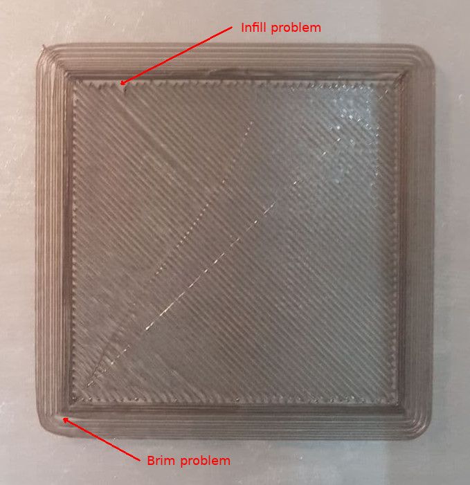
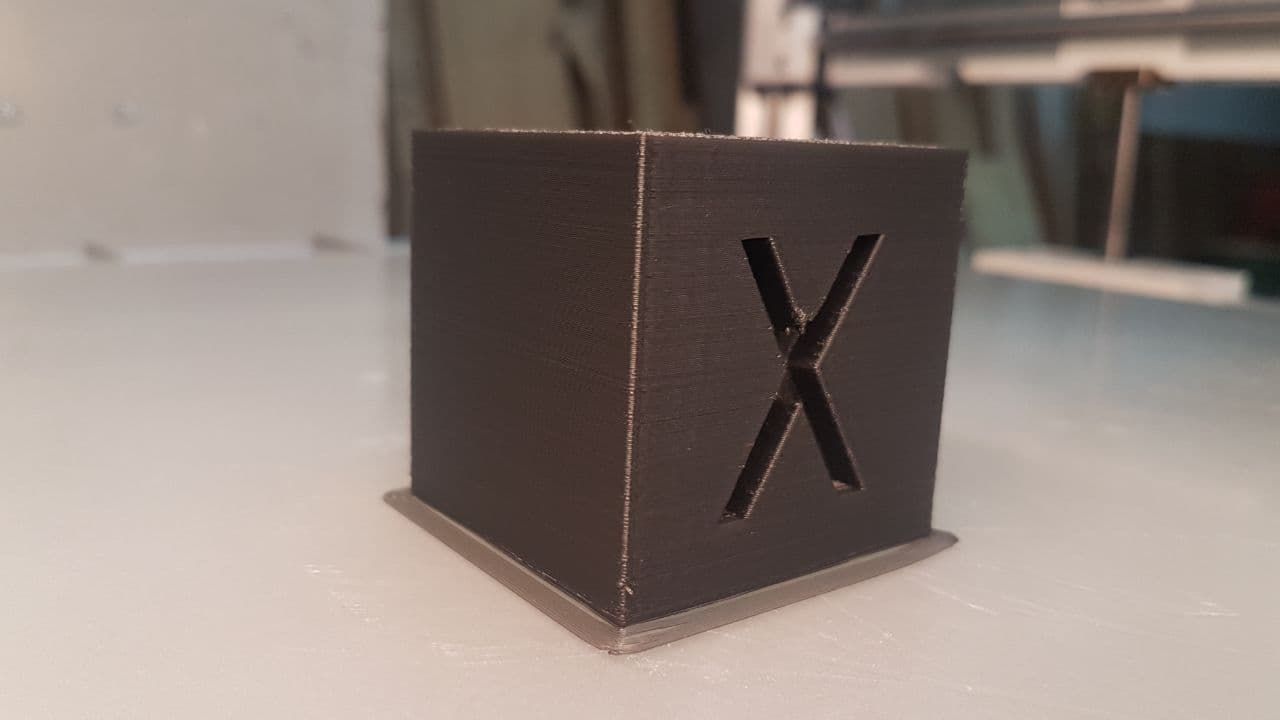
                                Zero layer of a test cube of 50x50x50 mm.
                                There are essentially 2 problems ....

                                1. Brim is not accurate. Perhaps it is due to poor adherence to the plan.
                                2. the filling is not precise and does not overlap the wall.

                                Maybe I need to change something in the settings. But what?

                                1 Reply Last reply Reply Quote 0
                                • bernardomattiucciundefined
                                  bernardomattiucci
                                  last edited by bernardomattiucci

                                  Test_xyzCube_4d.jpg Test_xyzCube_4c.jpg

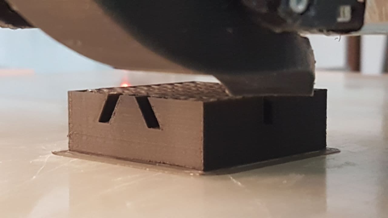
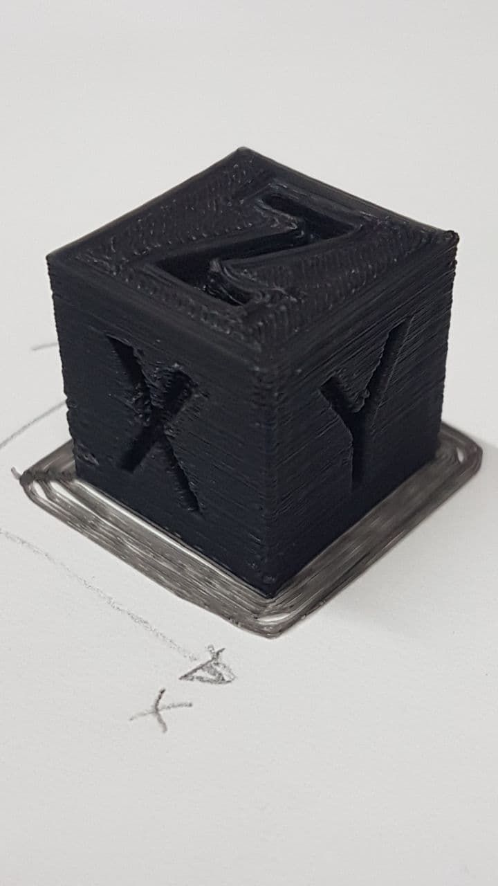
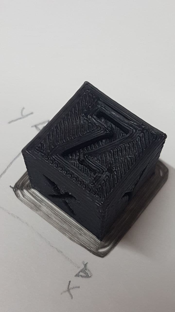
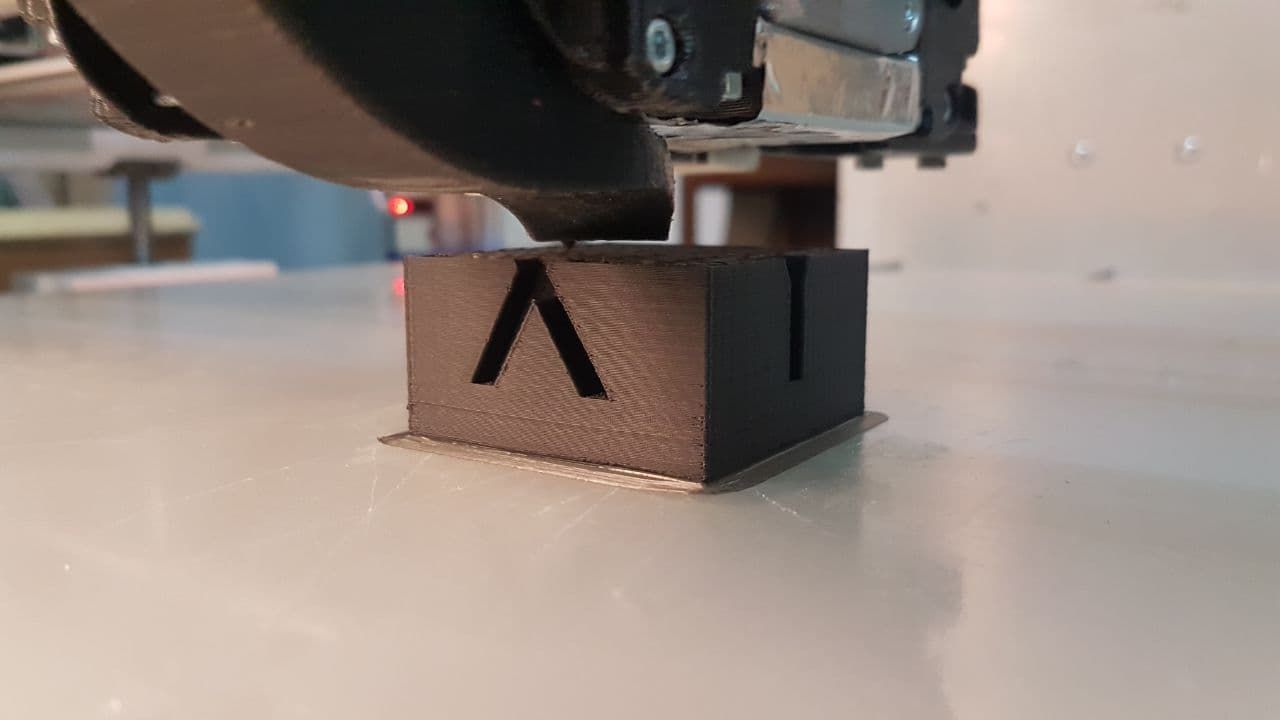
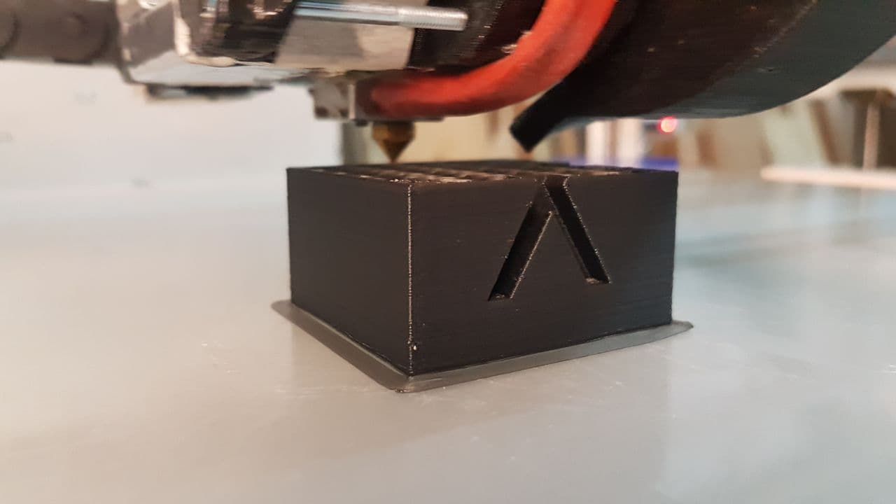
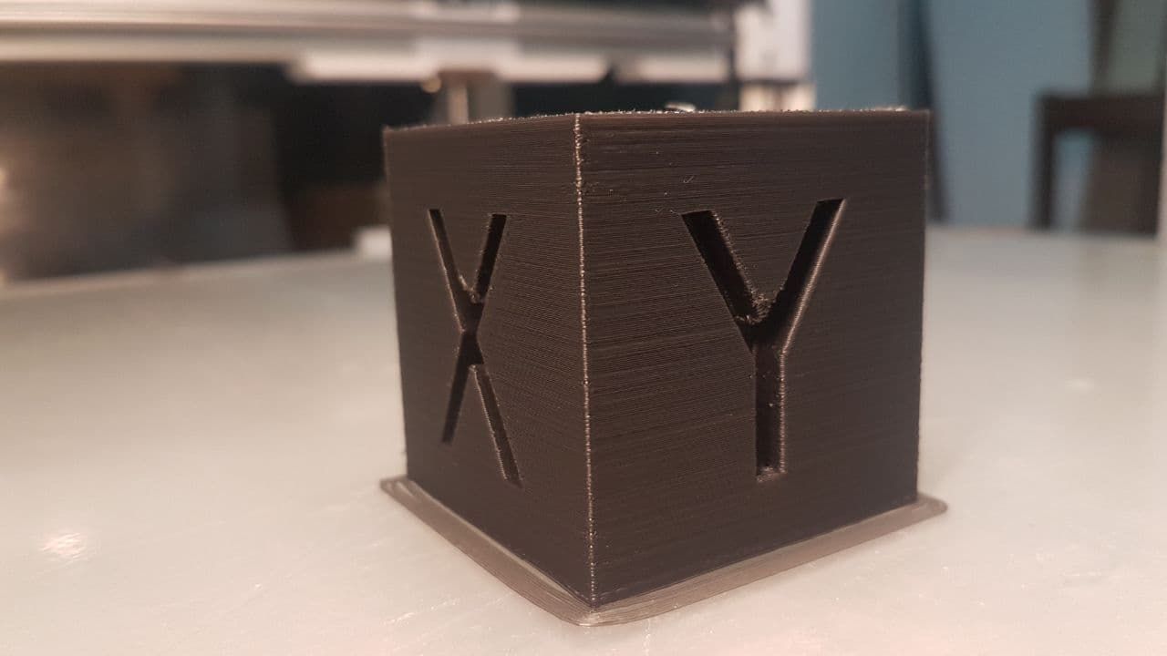
                                  In addition to modifying the speed of the walls again, with this larger test, the result looks better (apart from Layer 0). Perhaps, and this is my suspicion, the airflow of the layers fan is not suitable for small objects. If this is the case, I will have to redo the duct providing a vertical flow all around the hotend. So a more distributed flow than this, which remains concentrated in one corner.

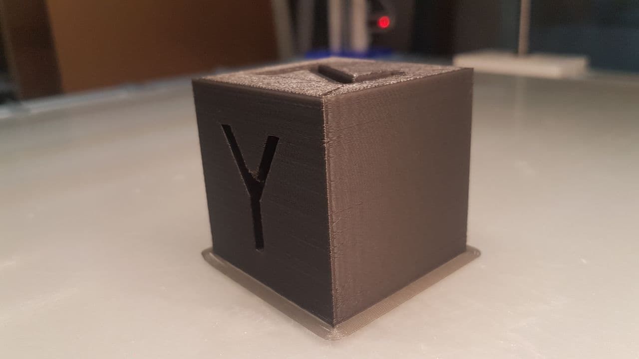
                                  At Layer 24 I paused the print to take a photo from above. In resuming the print you notice the slight error, especially on the left corner of the previous photo.
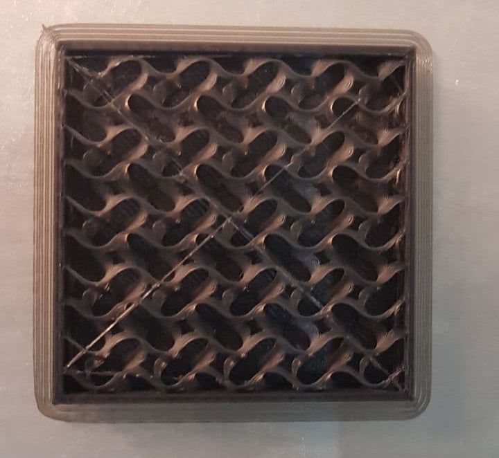
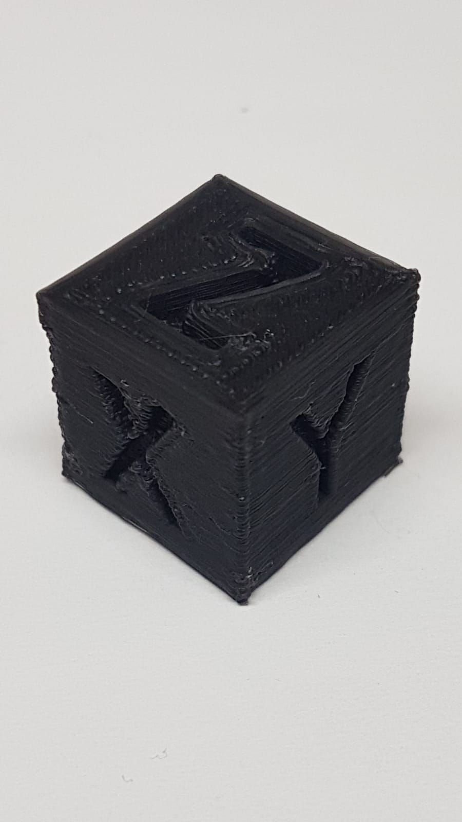
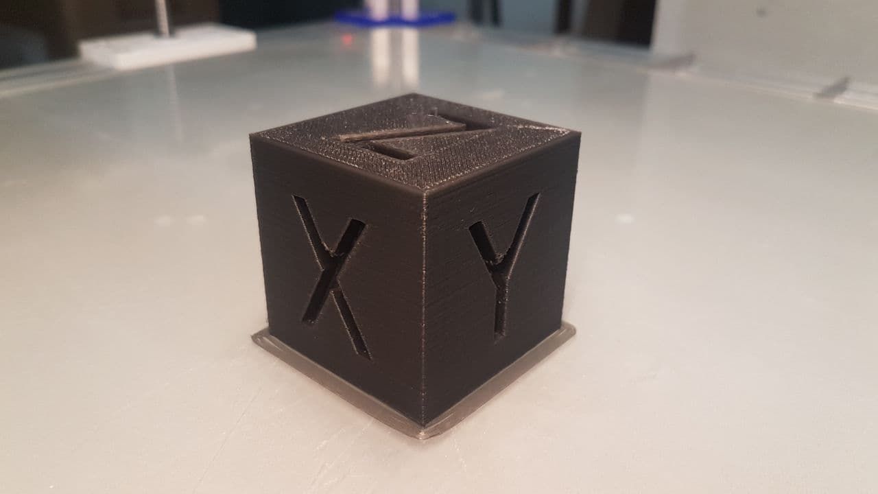
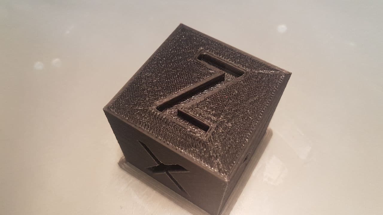
                                  Test_xyzCube_4e.jpg

                                  Layer 136:
                                  Test_xyzCube_4f.jpg
                                  Test_xyzCube_4g.jpg

                                  You see various errors / problems along the edges. They are almost certainly due to a non-optimal Jerk setting. Tomorrow I will try to improve!

                                  Anyway ... congratulations to everyone because this electronics are phenomenal!

                                  1 Reply Last reply Reply Quote 0
                                  • bernardomattiucciundefined
                                    bernardomattiucci
                                    last edited by

                                    And with these 5 photos I close the discussion.

                                    Test_xyzCube_4_end-1.jpg Test_xyzCube_4_end-2.jpg Test_xyzCube_4_end-3.jpg Test_xyzCube_4_end-4.jpg Test_xyzCube_4_end-5.jpg

                                    Thank you all

                                    1 Reply Last reply Reply Quote 2
                                    • First post
                                      Last post
                                    Unless otherwise noted, all forum content is licensed under CC-BY-SA