Slice hot end heater and HT thermistor help
-
trying to configure my hot end and thermistor but can't fathom it out, anyone shed some light on it guys?
mini5 with slice HT thermistor and 50w heater
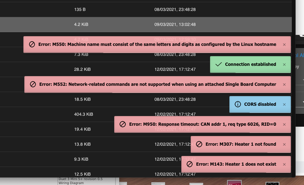
I changed the syntax M308 S1 P"1.temp1" and it disabled the heater, I since changed it back to bthe below but still disabled.
; HotEnd Heaters and Thermistor HotEnd
M308 S1 P"temp1" Y"thermistor" T500000 C1.196220e-7 ;define E0 temperature sensor Slice
M950 H1 C"1.out1" T1 ; Create HotEnd Heater
M307 H1 R2.277 C166.5:115.4 D6.87 S1.00 V22.9 B0 ; Hotend PID new version
M143 H1 S285 ; Set temperature limit for heater 1 to 285C HotEnd
M302 S185 R185

-
For the others: He's using a Duet 3 Mini 5+ in SBC mode.
I see one error there.
M950 H1 C"1.out1" T1 ; Create HotEnd Heater
Don't know where the 1 is coming from.
M950 H1 C"out1" T1 ; Create HotEnd Heater
is the right output name.
I would also post the whole config.g and put a "code" tag around it.
-
; General preferences G90 ; Send absolute coordinates... M83 ; ...but relative extruder moves ; Network M550 P"Pruset II MK3s" ; Set machine name M552 S1 ; Enable network ;*** Access point is configured manually via M587 M586 P0 S1 ; Enable HTTP M586 P1 S0 ; Disable FTP M586 P2 S0 ; Disable Telnet M575 P1 S1 B57600 ; Panel Due ; Drive Mappings M569 P0.0 S1 V0 ; Drive 0 goes forwards: X Axis M569 P0.1 S0 V0 ; Drive 1 goes backwards: Y Axis M569 P0.2 S1 V0 ; Drive 2 goes backwards: Z Axis M569 P0.3 S1 V0 ; Drive 3 goes forwards: E Axis M569 P0.4 S1 V0 ; Drive 4 goes backwards: Z Axis (at E1) ; Micrpstepping and Speed M350 X16 Y16 E16 Z16 I1 ; Configure microstepping with interpolation M92 X200.00 Y200.00 Z400.00 E830.00 ; Set steps per mm ; Speeds, Acceleration and Jerk M566 X240.00 Y240.00 Z24.00 E270.00 P1 ; Set maximum instantaneous speed changes (mm/min) M203 X7200.00 Y7200.00 Z723.00 E1200.00 ; Set maximum speeds (mm/min) M201 X1250.00 Y1250.00 Z1000.00 E500.00 ; Set accelerations (mm/s^2) M204 P1250.0 T1250.0 ; set print and travel accelerations (mm(s^2) ; Motor currents M906 X1000.00 Y1100.00 Z600.00 E700.00 I10 ; Set motor currents (mA) and motor idle factor in percent M84 S30 ; Set idle timeout ; Motor remapping for dual Z and axis Limits M584 X0 Y1 Z2:4 E3 ; two Z motors connected to driver outputs Z and E1 M671 X-37:287 Y0:0 S10 ; leadscrews at left (connected to Z) and right (connected to E1) of X axis ; Printer geometry M208 X0:250 Y-4:215 Z-0.5:205 ; X carriage moves from 0 to 250, Y bed goes from 0 to 210 M564 H0 ; allow unhomed movement ; Endstops for each Axis M574 X1 S3 ; Set endstops controlled by motor load detection M574 Y1 S3 ; Set endstops controlled by motor load detection ; Stallgaurd Sensitivy M915 X S-10 F0 H400 R0 ; Set X axis Sensitivity ;working 3.3 M915 Y S-10 F0 H400 R0 ; Set y axis Sensitivity ; woring 3.3 ; Input Shaper M593 F60 P4 S0.2 ; Input Shaping ; Z-Probe Super PINDA M574 Z1 S2 ; Set endstops controlled by probe M558 P5 C"^io3.in" I1 H1 F500 T4800 A30 S0.004 ; PINDA ; Probing Mesh Grid and Sheets M557 X24:221 Y10:195 P8 ; Define mesh grid for probing G31 P1000 X23 Y5 Z1.585 ; Textured Sheet ;G31 P1000 X23 Y5 Z1.280 ; PEI ; Heatbed Heaters and Thermistor Bed M308 S0 P"temp0" Y"thermistor" T100000 B4725 C7.060000e-8 ; Set thermistor + ADC parameters for heater 0 Bed M950 H0 C"out0" T0 Q100 ; Creates Bed Heater M307 H0 R0.238 C254.1 D10.82 S1.00 V22.9 B0 ; Bed PID new version M140 H0 ; Bed uses Heater 0 M143 H0 S120 ; Set temperature limit for heater 0 to 120C Bed ; HotEnd Heaters and Thermistor HotEnd M308 S1 P"1.temp0" Y"thermistor" T500000 C1.196220e-7 ;define E0 temperature sensor Slice M950 H1 C"1.out1" T1 ; Create HotEnd Heater M307 H1 R2.277 C166.5:115.4 D6.87 S1.00 V22.9 B0 ; Hotend PID new version M143 H1 S285 ; Set temperature limit for heater 1 to 285C HotEnd M302 S185 R185 ; Fans M950 F1 C"out5" Q250 ; Creates HOTEND Fan M106 P1 T45 S235 H1 ; HOTEND Fan Settings M950 F0 C"out6" Q100 ; Creates PARTS COOLING FAN M106 P0 H-1 ; Set fan 1 value, PWM signal inversion and frequency. Thermostatic control is turned off PARTS COOLING FAN ; Tools M563 P0 D0 H1 F0 ; Define tool 0 G10 P0 X0 Y0 Z0 ; Set tool 0 axis offsets G10 P0 R0 S0 ; Set initial tool 0 active and standby temperatures to 0C G91 G1 X1 Y1 Z1 G90 M83 M98 P"0:/macros/02_Functions/StartupFilamentSensorCheck" ; Runout Sensor Logic: Startup with filament = runout sensor active Startup without filament = autoload active -
; HotEnd Heaters and Thermistor HotEnd
M308 S1 P"temp1" Y"thermistor" T500000 B4723 C1.19622e-7  ;define E0 temperature sensor Slice HT
M950 H1 C"out1" T1					; Create HotEnd Heater
M307 H1 R2.277 C166.5:115.4 D6.87 S1.00 V22.9 B0 ; Hotend PID new version
M143 H1 S285                            ; Set temperature limit for heater 1 to 285C HotEnd
M302 S185 R185
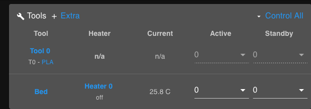
made a couple of amendments got heater back, deleted the trailing 0 from "C" and the errors went away but still -273 temp
-
@Argo said in Slice hot end heater and HT thermistor help:
Don't know where the 1 is coming from.
The leading number targets the can address of the board it's connected to in cases where you have expansion boards. 0 is the mainboard and then each canbus board after goes up by 1.
https://duet3d.dozuki.com/Wiki/RepRapFirmware_3_overview#Section_Pin_names_for_Duet_Num_3
-
Just as a sanity check this is what the configurator produces for a mini5 and slice thermistor.
M308 S1 P"temp1" Y"thermistor" T500000 B4723 C1.19622e-7 ; configure sensor 1 as thermistor on pin temp1
M950 H1 C"out1" T1                                       ; create nozzle heater output on out1 and map it to sensor 1
M307 H1 B0 S1.00                                         ; disable bang-bang mode for heater  and set PWM limit
M143 H1 S280                                             ; set temperature limit for heater 1 to 280C
Which looks the same as yours but maybe copy and paste it into yours to replace it in case there's some funky characters in there or something.
-
@Phaedrux I see, thanks for clarification.
Turns out it was a bad cable with it's brand new Slice Engineering thermistor and not an issue with the config.