New to Duet but heading to a major project. Advise needed.
-
Hi everyone,
We have made progress with OrientalMotors's closed loop encoder motor in conjunction with the 1XD board.
Just with ±STEP and ±DIR, we have been able to move it and within its software define the required HOME point, its maximum travel and the rest of the parameters. So it works and it does it very well, without a single lost step at any speed or force.
When we HOME to that axis from DWC, it moves to the home that we have defined correctly, and it waits until the timeout for an endstop to be pressed, which does not exist. Once the HOME timeout has expired, we can do a G92 X0 Y0 Z0 to define that this position is HOME and from there it works perfectly as the printer know their origins.
My questions are:
The motor driver has a HOME-END output pin that we would like to configure in any of the IN inputs of the 1DX board to function as the endstop trigger. The driver outputs a signal that indicates that it has reached home, which would be enough for the G28 to work on its own.
Also, would the ioX.in pins directly admit the 24v signal coming from the driver for this or would we also have to transform it to 5V?
How can I do this, what is the necessary configuration?Although the G28 when launched to the printer interprets it and makes the move to HOME, is there a way that when sending a G28, it can trigger a signal to the OUT pin of the 1XD so that the driver receives the signal command to go to HOME? It may not even be necessary.
The ioX.out signals only work with a maximum current of 3mA so I don't know if it will be enough current to drive the optocoupler that we use to change the signals from 24v to 5V and vice versa.
I think if could be possible at least to receive the HOME-END signal as endstop we could use a real closed loop with 1XD boards.
The next challenge would be to interpret a STALL signal the driver has, to return to home and pause, and then continue where the obstacle has occurred, but that would be another chapter.
-
I think the io inputs on the 1xd should be usable at 24v
Three digital inputs with permanent 27K pullup resistors, protected against over-voltage: io0.in, io1.in, io2.in
Example use - Alarm input, Brake Release input, EndstopBut I've sought clarity on whether they are 30v tolerant the same as the inputs on the duet3 mainboard.
-
Do you think I could test directly from the motor controller if there is no risk of burning the board?
The idea is that the signal received on that pin acts as an endstop that indicates to the firmware that it is at home.
-
Confirmed that they are also 30v tolerant.
If the output of the home signal is 24v it should be ok to test out. Is the signal high or low?
-
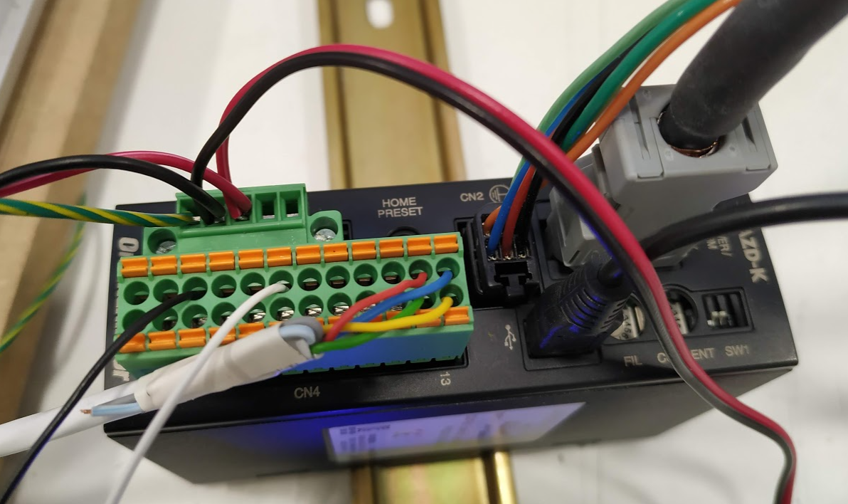
I have tried to connect the output pin of HOME-END of the driver to io0.in of the 1XD (121can) and the common of the driver to GND directly.
What I see with the various endstop configurations is the following:
M574 X1 S1 P "121.io0.in" makes HOME in the position where it is because the pin is active. It does not give homing failed. It needs to be inverted, so next try to follow.
M574 X1 S1 P "! 121.io0.in" searches for HOME correctly, but keeps waiting for it. It ends up giving homing failed. Inverting but still not Ok.
M574 X1 S1 P "^ 121.io0.in" makes HOME in the position where it is, as the first option. It does not give homing failed. Also needs to invert it.
M574 X1 S1 P "! ^ 121.io0.in" searches HOME correctly, but waits for it. It ends up giving homing failed.
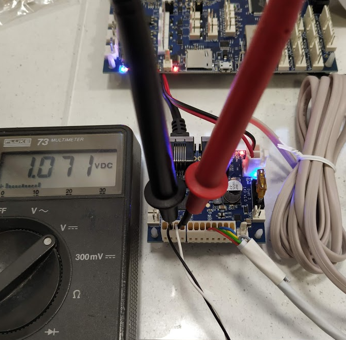
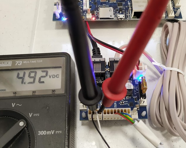
What I see is that when the driver activates the signal that they are in the HOME position, the voltage of the pin drops to 1.072v not to 0. When it is out of the home position, the pin has 4.92v.
Driver pin7 (white) positive home end OUT, and pin10 (black) common OUT pins:
Homed at the driver:
Away from home at the driver:
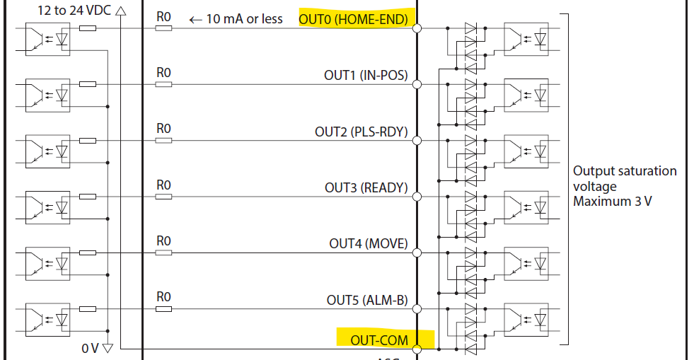
What I think is that these pins of the driver output do not draw voltage, they only draw current because it is like a switch. I don't know whether to inject 24v into the signal pin (white cable pin) in the driver (which tolerate it) to see if there is any change when adding voltage to the signal. It may be necessary to put a resistor to reduce the maximum current to reduce at 10mA or less.
The driver schematic for that pin is this:
This at least is a leap forward, which gives me hope that it can work.
-
Tested to inject 24v from the driver into the signal pin and same behaviour. It is like the change of the pin state were not recognized.
-
A voltage of 1.072V in io1.in should be low enough to signal a low level (the maximum guaranteed to read as low is 1.5V). Do not use the ^ character to activate the pullup resistor; if you do then the required input voltage will be lower.
If you use M119 to query the endstop status, does it report the expected state?
-
If you have OUT_COM from the motor controller pin 10 connected to Duet 1XD ground like you show, you are connecting similar to this diagram in your motor controller manual:
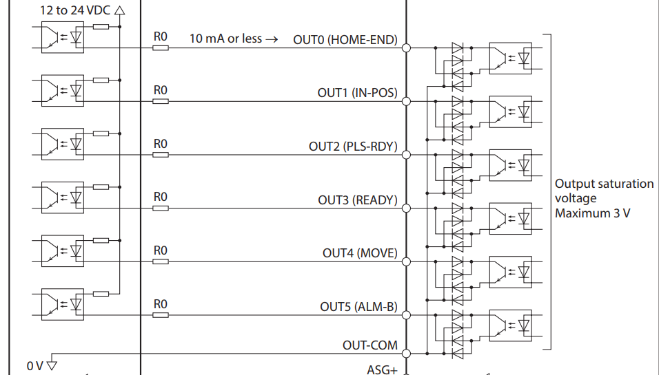
(Duet on left, motor controller on right of the diagram)And that means you should have a pull-up resistor (I don't know, 4K Ohms seems OK) to at least 12 Volts from the signal line on your 1XD.
-
@alankilian said in New to Duet but heading to a major project. Advise needed.:
And that means you should have a pull-up resistor (I don't know, 4K Ohms seems OK) to at least 12 Volts from the signal line on your 1XD.
The IO1.in pin already has a pullup resistor to +5V. As the OP said that with the axis not homed he measured 4.92V on the pin, that would appear to be sufficient. The minimum allowed logic high level is 2.5V.
-
We've connected OUT COM straight from the driver to GND on 1XD board, and OUT0 to the ioX.in pin on the 1XD as can be seen in the pictures. Test with all three io pins, same result.
Also tested injecting 24volt plus signal into the signal pin at the driver side.
We also see the signal activation in the driver side with internal software monitor and with a osciloscope when reached the home defined in the internal encoder.
So suspect there is something in the config or in the way the 1XD board take the signal to get endstop trigger.
I'll test right now a external mechanical switch to see if the endstops are triggered in these pin.
-
@Marcossf, does M119 report the correct state?
What GCode commands are you using to home the axis?
-
Yes, M119 report right when M574 X1 S1 P "121.io0.in" but stops at the actual position of the axis, not in home.
The driver trigger the HOME-END signal just when the encoder position HOME is reached, but with this endstop config stops where the X axis is. Seems to be inverted.Home commands are isued from DWC button or G28 X0 command. If cheat G92 X0 the controller think its homed and can move the axis freely.
If I invert the endstop logic (!), issue a G28 X0 command seeking for home, it moves to home and when reached it, the driver stops, move a little forward and back to home point as if the endstop was triggered, the signal stay in low 1.07v and not inform there is home to these axis, just X homing failed.
-
Maybe can invert the signal from the driver just for test? Common OUT to io0.in pin and HOME-END signal to 1XD gnd as if where a current sink signal.
I don't know if 1XD GND pin can support that.
-
The assumption with homing is that you'd be doing a G1 H1 X move until the endstop status changes. Then the position is set to either the M208 min or max and the axis marked homed. So as long as it's sending that homed position signal during that homing move it should be fine.
The back off move and then rehome could probably be removed in your case.
Alternatively you could just change your homing file to move to that homed position and then use G92 to set that position as homed.
-
@phaedrux The problem that we have is the signal received from the motor driver doesn't trigger the endstop pin. I don't know why. We can see the signal activation in the driver side as can be seen in the photos posted above.
Doing it with a simple switch works well, so the 1XD signal pin or homex.g routine isn't the problem.
; homex.g
; called to home the X axis
;
; generated by RepRapFirmware Configuration Tool v3.2.3 on Wed Mar 24 2021 10:52:22 GMT+0100 (hora estándar de Europa central)
G91               ; relative positioning
;G1 H2 Z5 F6000    ; lift Z relative to current position
G1 H1 X-205 F1800 ; move quickly to X axis endstop and stop there (first pass)
;G1 H2 X5 F6000    ; go back a few mm
;G1 H1 X-205 F360  ; move slowly to X axis endstop once more (second pass)
;G1 H2 Z-5 F6000   ; lower Z again
G90               ; absolute positioning
It is more a question of why it doesn't interpret the signal change when it is within the activation limits as @dc42 has said.
-
Perhaps you need to enable to pullup resistor on the pin you're trying to use.
Add
^to the pin name in the M574. -
@phaedrux said in New to Duet but heading to a major project. Advise needed.:
Perhaps you need to enable to pullup resistor on the pin you're trying to use.
Add
^to the pin name in the M574.Tried already:
- M574 X1 S1 P "121.io0.in" makes HOME in the position where it is because the pin is active. It does not give homing failed. It needs to be inverted, so next try to follow.
- M574 X1 S1 P "!121.io0.in" searches for HOME correctly, but keeps waiting for it. It ends up giving homing failed. Inverting but still not Ok.
- M574 X1 S1 P "^121.io0.in" makes HOME in the position where it is, as the first option. It does not give homing failed. Also needs to invert it.
- M574 X1 S1 P "! ^121.io0.in" searches HOME correctly, but waits for it. It ends up giving homing failed.
At this moment, we're waiting for receive a new driver, because the USB interface to configure it was burned after a bunch intensive pin testing (at least we think that must have happened this, because it does not detect the USB anymore but moves).
So we need patiently wait for it. Meanwhile we have a lot of others task/problems to resolve. -
After receiving a new Oriental Motor Driver, and tested with 1XD homing works as expected.
I can say there is a real Closed Loop system that works with Duet. It isn't cheap at all, but really accurate and robust industrial grade motor and driver for anyone searching a real closed loop system.
There wasn't a config error on Duet config.g when we did M574 X1 S1 P"!40.io0.in" because it worked this time. Maybe a error or fail in the other driver.
Now it stops at exactly the step=0 feedback from the driver and notify RRF the endstop trigger. The connection was directly from pinOUT home signal from the driver io0.in and gnd. No boards, relays or signal level converters in between.Still wondering how the first time we tested with the other driver didn't worked, but we will investigate it.
Now we need to see how to "M84 disable motors" can trigger the Free move function in the OM driver, but it isn't mandatory to get full working machine.
We are happy
