Duet Wifi Wall Split
-
Hello. A couple months ago, I made a post of a wall split in the x direction that occurred on the perimeters of my prints. After spending a lot of time diagnosing the issue, re-flashing the firmware seemed to fix the problem. About a month ago, the wall split issue re-appeared, but in the y direction. I tried re-flashing the firmware but that did not solve the issue. I'm not to sure what is the cause of this issue. Any help would be greatly appreciated!
-
Here is my config:
; Configuration file for Duet WiFi (firmware version 3)
; executed by the firmware on start-up
;
; generated by RepRapFirmware Configuration Tool v3.2.3 on Wed Feb 24 2021 16:32:46 GMT-0600 (Central Standard Time); General preferences
G90 ; send absolute coordinates...
M83 ; ...but relative extruder moves
M550 P"Anet A8" ; set printer name
M575 P1 B57600 S1 ;Set baud rate Duet Board.
M575 P0 B57600 S1 ;Set baud rate USB; Network
M552 S1 ; enable network
M586 P0 S1 ; enable HTTP
M586 P1 S0 ; disable FTP
M586 P2 S0 ; disable Telnet; Drives
M569 P0 S1 ; physical drive 0 goes forwards
M569 P1 S1 ; physical drive 1 goes forwards
M569 P2 S0 ; physical drive 2 goes backwards
M569 P3 S1 ; physical drive 3 goes forwards
M584 X0 Y1 Z2 E3 ; set drive mapping
M350 X16 Y16 Z16 E16 I1 ; configure microstepping with interpolation
M92 X80.28 Y100.65 Z399.10 E413.72 ; set steps per mm
M566 X600.00 Y600.00 Z18.00 E1500.00 ; set maximum instantaneous speed changes (mm/min)
M203 X7200.00 Y7200.00 Z180.00 E6000.00 ; set maximum speeds (mm/min)
M201 X2000.00 Y2000.00 Z100.00 E12000.00 ; set accelerations (mm/s^2)
M906 X1100 Y500 Z500 E800 I30 ; set motor currents (mA) and motor idle factor in per cent
M84 S30 ; Set idle timeout; Axis Limits
M208 X-13 Y5 Z0 S1 ; set axis minima
M208 X220 Y220 Z240 S0 ; set axis maxima; Endstops
M574 X1 S1 P"!xstop" ; configure active-high endstop for low end on X via pin !xstop
M574 Y1 S1 P"!ystop" ; configure active-high endstop for low end on Y via pin !ystop
M574 Z1 S1 P"!zstop" ; configure active-high endstop for low end on Z via pin !zstop; Z-Probe
M950 S0 C"exp.heater3" ; create servo pin 0 for BLTouch
M558 P9 C"^zprobe.in" H5 F120 T6000 ; set Z probe type to bltouch and the dive height + speeds
G31 P500 X-32.1 Y2.919 Z0.614 ; set Z probe trigger value, offset and trigger height
M556 S81 X0.35 Y-1.0 Z0.35 ; set orthogonal axis compensation parameters
M557 X20:180 Y20:212 S32 ; define mesh grid; Heaters
M308 S0 P"bedtemp" Y"thermistor" T100000 B4725 C7.06e-8 ; configure sensor 0 as thermistor on pin bedtemp
M950 H0 C"bedheat" T0 ; create bed heater output on bedheat and map it to sensor 0
M307 H0 R0.167 C510.3 D2.06 S1.00 ; disable bang-bang mode for the bed heater and set PWM limit
M140 H0 ; map heated bed to heater 0
M143 H0 S130 ; set temperature limit for heater 0 to 130C
M308 S1 P"e0temp" Y"thermistor" T100000 B4725 C7.06e-8 ; configure sensor 1 as thermistor on pin e0temp
M950 H1 C"e0heat" T1 ; create nozzle heater output on e0heat and map it to sensor 1
M307 H1 R1.238 C55.7 D9.19 S1.00 ; disable bang-bang mode for heater and set PWM limit
M143 H1 S290 ; set temperature limit for heater 1 to 275C; Fans
M950 F0 C"fan0" Q500 ; create fan 0 on pin fan0 and set its frequency
M106 P0 S0 H-1 ; set fan 0 value. Thermostatic control is turned off
M950 F1 C"fan1" Q100 ; create fan 1 on pin fan1 and set its frequency
M106 P1 S1 H-1 ; set fan 1 value. Thermostatic control is turned on
M950 F2 C"fan2" Q50 ; create fan 2 on pin fan2 and set its frequency
M106 P2 S150 H-1 ; set fan 2 value. Thermostatic contol is turned off; Tools
M563 P0 S"Extruder 1" D0 H1 F0 ; define tool 0
G10 P0 X0 Y0 Z0 ; set tool 0 axis offsets
G10 P0 R0 S0 ; set initial tool 0 active and standby temperatures to 0C; Custom settings are not defined
G29 S1; Miscellaneous
M575 P1 S1 B57600 ; enable support for PanelDue
T0 ; select first tool -
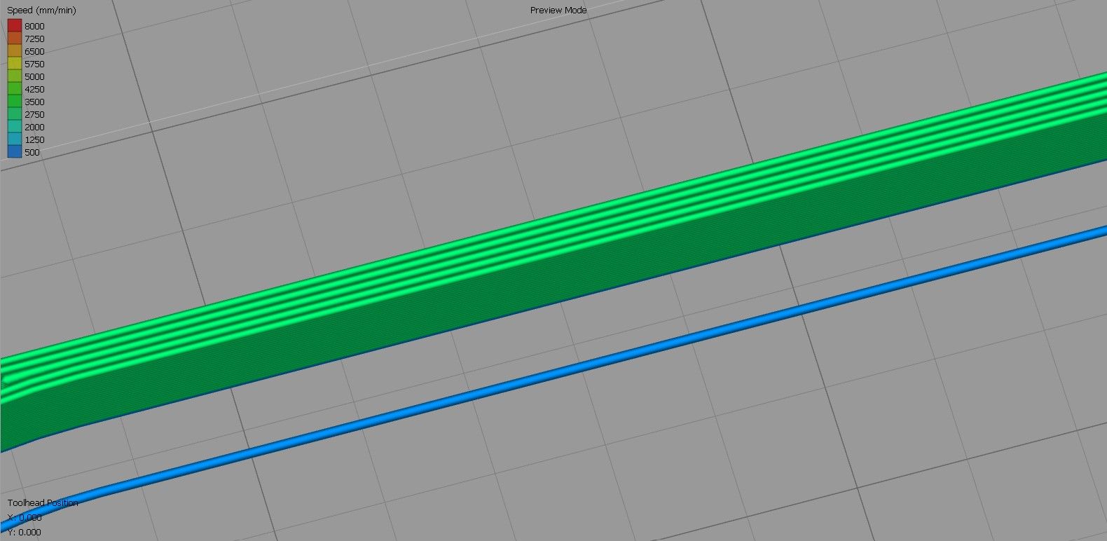
I can't see why re-flashing would have any impact on that. It seems more like underextrusion keeping the walls from melding completely. Possibly the slicer isn't doing any gap fill since it's too close for infill but the extrusion width isn't enough to just use walls.
-
@phaedrux I use an extrusion width of 0.4mm. My walls are 2mm thick which the wall should be composed of 5 lines of equal thickness. There should be no infill although Simplify3D thinks that the line between the inner and outer perimeter is a "thin wall". I currently have "allow extrusion fill" checked, and a perimeter overlap of 50%.
-
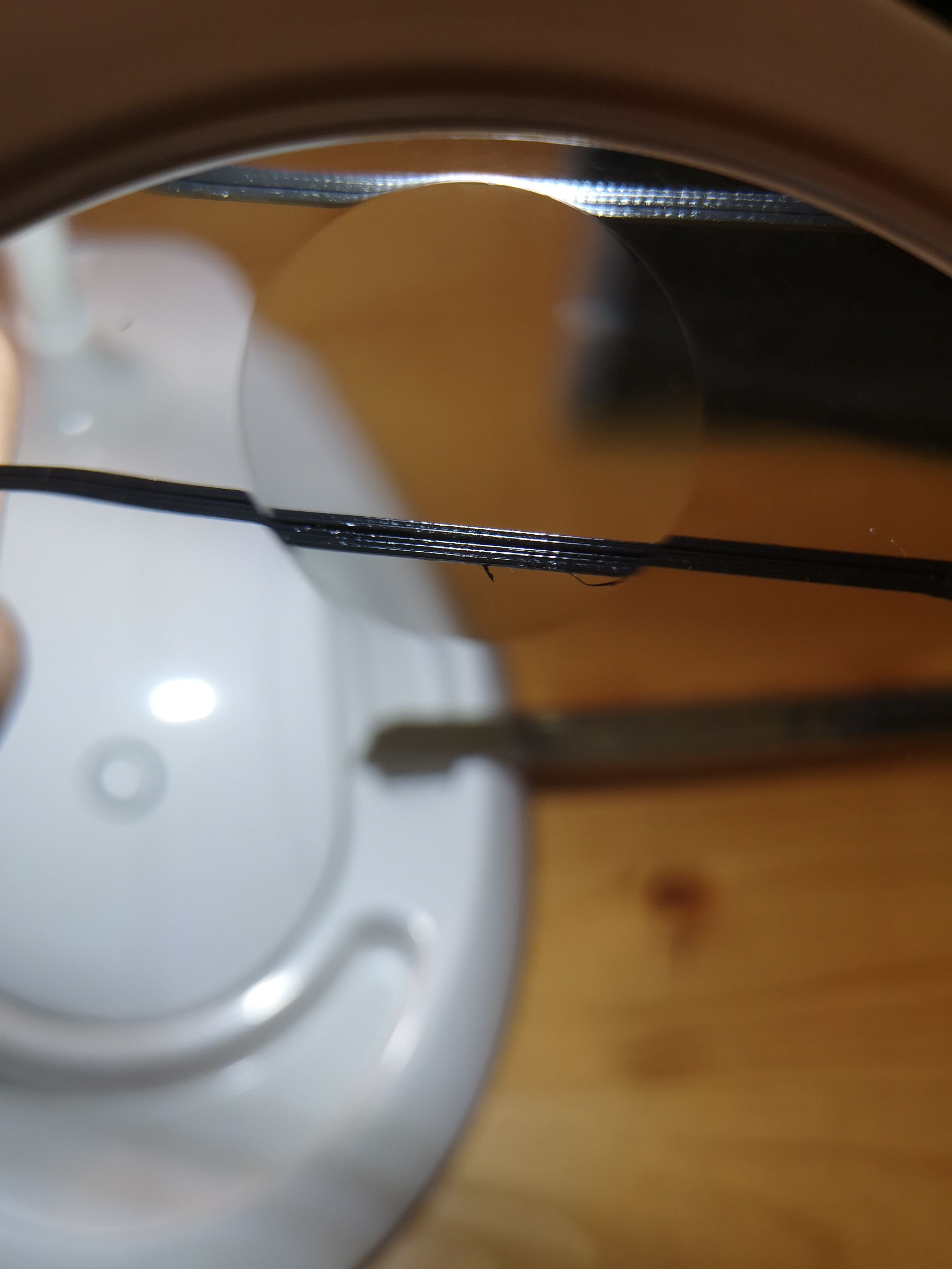
Here is a close-up picture of the gap. The two perimeters are not touching at all with the other 3 lines. I also boosted the extrusion multiplier which did nothing at all.

-
I don't use Simplify3D myself, so I'm not much help with settings suggestions there, but I know that in PrusaSlicer using thin wall detection and gap fill you'd likely have no problem printing it.
-
@phaedrux I tried prusa slicer. Same issue but elsewhere in the part.
-
@tommygunz FYI for PrusaSlicer at least, two 0.4mm walls does not make a 0.8mm wall (as filament comes out with rounded edges it overlaps them). It should tell you what the wall thickness will be for a given linewidth and number of perimeters. Here's a screengrab from mine (with a 0.35mm nozzle and some non-standard line widths)
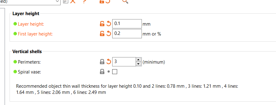
They have a knowledgebase article on it:
https://help.prusa3d.com/en/article/layers-and-perimeters_1748/If you're using a 0.4mm linewidth with a 0.4mm nozzle that might give you some trouble - general advice is to have the linewidth a bit wider (e.g. 0.5mm). You use a thinner linewidth for supports when you want them to be brittle
Failing that, maybe you're printing a bit too cold so that the layers/perimeters can't bond together. Or could be you've got some mechanical backlash that means your motion isn't quite perfect (and the lines aren't overlapping enough to still bond).