Filament Monitor problem
-
I still cannot get this right. I have two laser monitors wired and with the following confiig.
I have filament in micro-switches wired as well.
M591 D0 P6 C"E0stop" R40:120 E3.0 S0
M591 D1 P6 C"E1stop" R40:120 E3.0 S0
The printer will run and the diodes flicker on the monitors.
however if I pull the filament present micro switch out, the printer will still run ( which means it will not sense if the filament is not present.However if I change the S0 to S1, the machine will not start and give an error that filament is not present.
(the switch is pressed with filament present)
Printing paused no filament in Extruder 0
I cant get the hang out of it... -
@mendelevium @mendelevium I am taking a look at everything..
Will try to give an accurate concise of what is happening
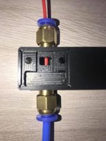
I mounted the pcb in a housing I designed, machined from Black POM with a 1.5mm end-mill and the filament passes through a 2mm hole so that the filament is positioned in a way so as not to play.
I have measured the distance from the face of the PCB (not the laser ) to the filament diameter and is 6.4mm. Is this correct?
I am also running 3+ firmware and the boards are V1.2
The switch is Normally open when no filament is present.
I have tried to put P as 5 but filament or no filament the machine starts.
I tested M591 D0 to test ;- it says no data received with filament physically present and tested again without filament and obtained the same response.
M591 D0
Duet3D laser filament monitor v1 on pin e0stop, enabled, allow 1% to 600%, check every 3.0mm, calibration factor 1.000, no data received!Also the board
s leds colors flash a green and blue in alternate fashion with stationery filament/No filament
When the filament is in movement, the green led does not flashes while the blue led flashes incessantly.Conclusion;-
With S=1 and P=6 machine sends error that no filament is present when a job is started and is paused.
With S=0 machine starts up and proceeds
With S=1 and P=5 leds flash alternatively between blue and green, filament present or not present the leds remain like this but when moved the Green led stops flashing and the led starts blinking incessantly.
in this condition the machine will start with no errors. -
-
@mendelevium
The instructions say....
*****On startup, after a few seconds the green LED on the filament monitor will flash 3 times if initialisation and self-test are successful. The green and red LEDs will then flash periodically indicating communication to the Duet. If the filament is moving, the green LED will flash more frequently.italicised textlooks like my board has a blue led and not a red led. On switching on the Blue Led will flash 3 times and then the green and Blue Led`s will flash as described then when filament moves the blue will flash more frequently.
Conclusion.
sensor initializing correctly but I have a
Blue Led instead of Green Led
Green Led instead of Red Led -
@mendelevium All I can think of is to try putting a two-pin jumper on the filament-out-switch pins and see if it THEN see filament.
That would indicate a problem in your connector, wiring or switch.
I'm just guessing at things you've probably tried already just to help.
Do you have a Volt/Ohm meter so you can test the switch?
Can you send good photos of the wiring?
I got mine working with a filament-out switch, and I'm configured the same as you are, so......
-
@alankilian
Thanks for replying brother.
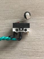
I have tried that... The switch functions very well I upload two photos so you can see. The switch is correctly wired- Common and Normally open (it will switch on when the filament is in place) You can also see where I soldered the wires.
What are the colors of your led's ? mine flash blue and green.. There is no red..Uphill struggle with this project from start to end it seems

May I ask to confirm;- The S0/S1 enables/disables the microswitch function right?
if this is correct, what is very sure is that;when S1 is enabled, the microswitch, released (no filament) or pressed (filament present) there is an error that there is no filament present and system sends the machine on pause. no printing can take place. The switch is not sending any signal. I checked the switch and I have them in both extruders and both behaving as such.
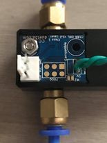
The switch is soldered to the board. I put the wire through the hole and soldered it. can`t think of anything.The sensor is working as when I move the filament in it, the Blue LED blinks repeatedly.
the soldering looks ok to me...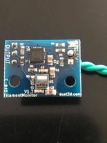
-
@mendelevium My sensor if different than yours.
Here's a photo:
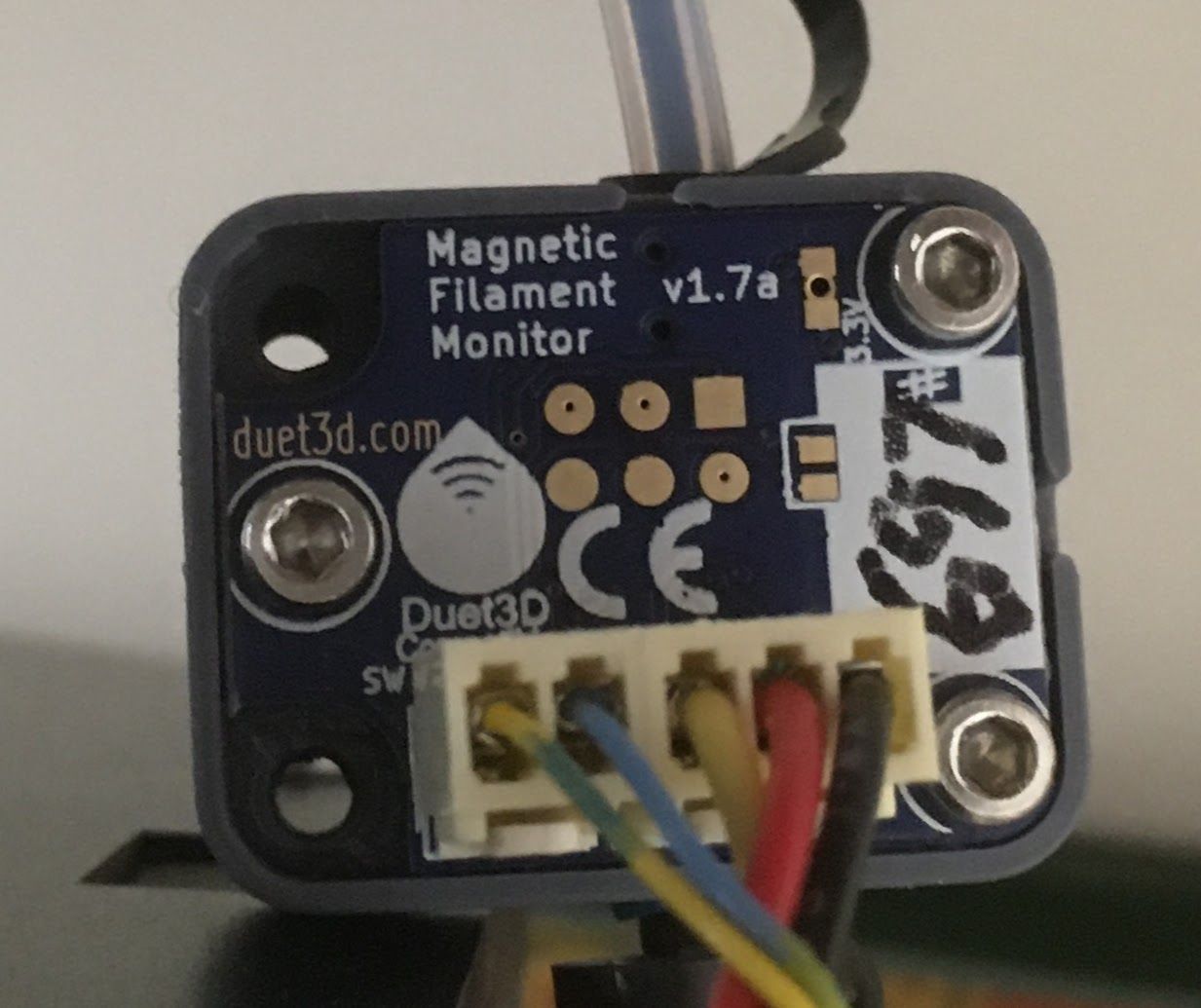
S0/S1 disables the entire sensor.
P6 is a sensor with a switch and P5 is a sensor without a switch, so that enables and disables the switch but leaves the sensor active.Try using a bit of wire and jumpering between the two pads on the PCB where you soldered the switch wires and see if it THEN senses the filament.
-
@alankilian
that is a magnetic type sensor.. What I will now check is the wiring to be 100% sure. That is my only trump card. I have a new sensor and will try it our and see. The laser is possibly working and it could be the wire sending the signals but for the two sensor wiring it is a bit far fetched.... -
@mendelevium one problem that I can see is that neither M591 nor M122 reports whether the switch detects filament present or not, which makes it hard to test that filament present switch. I will fix that.
Edit: added this to 3.3RC2.
-
@dc42
definitely, what I found out is that the filament present switch was not actuating 100%. The roller was not being pushed enough and the sensor was not receiving a signal. Alankilian confirmed that my config script was correct. When something crops up, we do not know if it is associated with the software, the hardware or the wiring and we would need to eliminate these one by one.There is then the issue of the sensitivity of various different filaments. I use simplify 3d... and what I find good in Simplify 3d is the starting scripts.
My slicer profiles I have created them to suit different printers and I have them sub divided with different materials @dc42, I have not tried it yet but I think it makes sense that the commands are put in the starting scripts with different R values according to the sensitivity of material being used.
"M591 D0 P6 C"E0stop" R40:120 E3.0 S0
M591 D1 P6 C"E1stop" R40:120 E3.0 S0"what do you think about this idea?
-
@mendelevium said in Filament Monitor problem:
My slicer profiles I have created them to suit different printers and I have them sub divided with different materials @dc42, I have not tried it yet but I think it makes sense that the commands are put in the starting scripts with different R values according to the sensitivity of material being used.
"M591 D0 P6 C"E0stop" R40:120 E3.0 S0
M591 D1 P6 C"E1stop" R40:120 E3.0 S0"
what do you think about this idea?When using the laser filament monitor, that makes sense. In general it should not be necessary when using the magnetic filament monitor, except possibly when using TPU.