Bed Level compensation not working correctly
-
Please share the full config.g, homeall/homez, bed.g, and the slicer start gcode.
What firmware version?
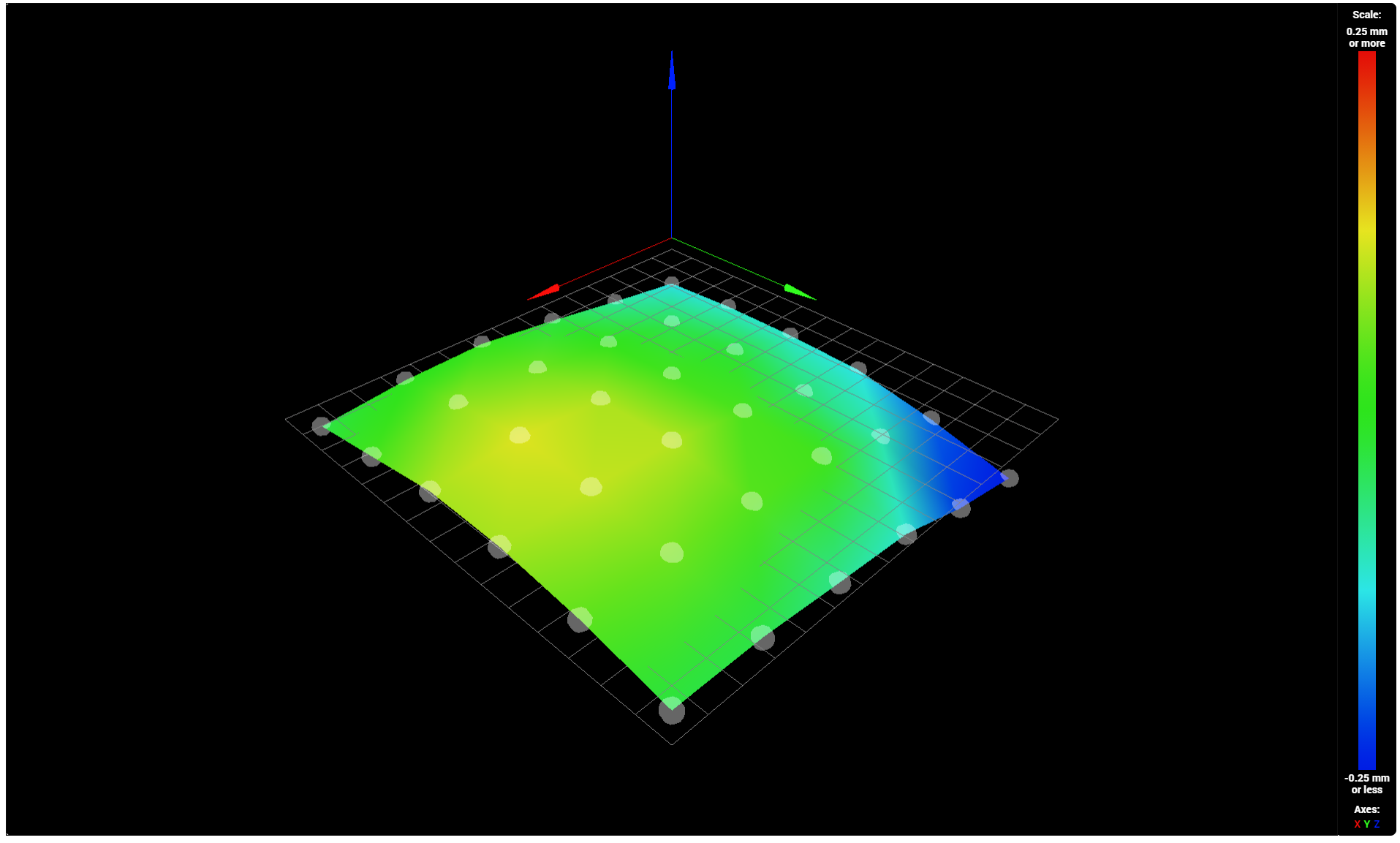
Have you run a G29 and generated a heightmap? It would be helpful to see what the resulting image of the bed surface looks like.
For reference the auto leveling docs are here: https://duet3d.dozuki.com/Wiki/Bed_levelling_using_multiple_independent_Z_motors
And mesh here: https://duet3d.dozuki.com/Wiki/Using_mesh_bed_compensation -
Hi.
There are two features to help with getting good printing that are related to the bed.
1 Mesh Compensation
2 Bed Leveling (auto or manual)You used the term "bed level compensation" so I am not sure which you are referring to - perhaps both.
A G32 command is used in conjunction with the file bed.g to perform bed leveling.
A G29 command is used in conjunction with the file mesh.g to create the height map needed for mesh compensation.
The docs you may have encountered can be out of date or simply wrong.
In bed.g you would have a small number of G30 P# commands to probe the bed and perform the leveling procedure. Then you would have a single G30 command to set the Z=0 datum which may have changed due to the leveling.
In mesh.g you would have a M557 command to specify the grid that will determine where the bed is probe to create the height map. A G29 S1 command will then be used at some point to load the height map and enable mesh compensation. Remember that it is important to set the Z=0 datum (using a single G30) before creating/loading the height map.
There are some different opinions on where to set the Z=0 datum but I always positioned the probe to the center of the printable are. Assuming a a printable area of 300 x 200 I would position the probe at 150, 100.
Frederick
-
I've seem people post their configs into a scrollable window. I don't know how to do that. I tried the upload file option but that gives me a parser error every time.
Firmware 3.1.1
Just to clarify, I mean bed compensation.
-
@steveps3 said in Bed Level compensation not working correctly:
I've seem people post their configs into a scrollable window. I don't know how to do that. I tried the upload file option but that gives me a parser error every time.
Firmware 3.1.1
Just to clarify, I mean bed levelling
You posted a image of your height map which is used for mesh compensation.
Bed leveling (auto or manual) is a different feature designed to achieve just what the name suggests - a level bed - using either multiple Z steppers (2, 3, 4) or multiple adjustment "thumb" screws that are turned by hand.
To paste code into a scrollable region you use the </> "button". You click it and it inserts a line of three ' characters, a line of "code text" and another line of three ' characters. You replace the "code text" with your own code by typing or pasting.
this is line 1 this is line 2 this is line 3 -
Config.h
; Configuration file for Duet WiFi (firmware version 3)
; executed by the firmware on start-up
;
; generated by RepRapFirmware Configuration Tool v3.1.4 on Fri Jul 24 2020 22:00:54 GMT+0100 (British Summer Time)

; General preferences
G90                                                ; send absolute coordinates...
M83                                                ; ...but relative extruder moves
M550 P"CoreXY"                                     ; set printer name
M669 K1                                            ; select CoreXY mode

; Network
M552 S1                                            ; enable network
M552 P192.168.1.254

M586 P0 S1                                         ; enable HTTP
M586 P1 S0                                         ; disable FTP
M586 P2 S0                                         ; disable Telnet

; Drives
M569 P1 S1                                         ; physical drive 1 goes forwards
M569 P0 S1                                         ; physical drive 0 goes forwards
M569 P2 S0                                         ; physical drive 2 goes backwards
M569 P3 S0                                         ; physical drive 3 goes forwards
M569 P4 S0                                         ; physical drive 4 goes forwards
M584 X1 Y0 Z2:4 E3                                 ; set drive mapping
M671 X0:0 Y-20:220 S5                            ; leadscrews at front (connected to Z) and back (connected to E1) of Y axis
M350 X16 Y16 Z16 E16 I1                            ; configure microstepping with interpolation
;M92 X100.00 Y100.00 Z400.00 E409.00                ; set steps per mm
M92 X100.00 Y100.00 Z400.00 E409.00                ; set steps per mm
M566 X1000.00 Y1000.00 Z100.00 E1500.00            ; set maximum instantaneous speed changes (mm/min)
M203 X20000.00 Y20000.00 Z900.00 E3600.00          ; set maximum speeds (mm/min)
M201 X800.00 Y800.00 Z30.00 E250.00                ; set accelerations (mm/s^2)
M906 X900 Y900 Z1500 E1200 I30                       ; set motor currents (mA) and motor idle factor in per cent
M84 S30                                            ; Set idle timeout

; Axis Limits
M208 X0 Y0 Z0 S1                                   ; set axis minima
M208 X295 Y295 Z295 S0                             ; set axis maxima
M557 X00:290 Y00:290 S45:45                        ; define mesh grid

; Endstops
M574 X1 S1 P"xstop"                                ; configure active-high endstop for low end on X via pin xstop
M574 Y2 S1 P"ystop"                                ; configure active-high endstop for high end on Y via pin ystop
;M574 Z1 S2                                         ; configure Z-probe endstop for low end on Z
M574 Z1 S2 P"zstop+e1stop" ; configure active-high endstops for low end on Z via pins zstop and e1stop

; Z-Probe
M950 S0 C"exp.heater3"                             ; create servo pin 0 for BLTouch
M558 P9 C"^zprobe.in" H3 F160 T6000                ; set Z probe type to bltouch and the dive height + speeds
G31 P500 X0 Y0 Z3.75                               ; set Z probe trigger value, offset and trigger height

; Heaters
M308 S0 P"bedtemp" Y"thermistor" T100000 B4138     ; configure sensor 0 as thermistor on pin bedtemp
M950 H0 C"bedheat" T0                              ; create bed heater output on bedheat and map it to sensor 0
M140 H0                                            ; map heated bed to heater 0
M143 H0 S120                                       ; set temperature limit for heater 0 to 120C
M308 S1 P"e0temp" Y"thermistor" T100000 B4138      ; configure sensor 1 as thermistor on pin e0temp
M950 H1 C"e0heat" T1                               ; create nozzle heater output on e0heat and map it to sensor 1

; Fans
M950 F0 C"fan0" Q500                               ; create fan 0 on pin fan0 and set its frequency
M106 P0 S0 H-1                                     ; set fan 0 value. Thermostatic control is turned off
M950 F1 C"fan2" Q500                               ; create fan 1 on pin fan1 and set its frequency
M106 P1 S0 H1 T45                                  ; set fan 1 value. Thermostatic control is turned on


; Tools
M563 P0 D0 H1 F0                                   ; define tool 0
G10 P0 X0 Y0 Z0                                    ; set tool 0 axis offsets
G10 P0 R0 S0                                       ; set initial tool 0 active and standby temperatures to 0C

; Custom settings are not defined

; Miscellaneous
M501                                               ; load saved parameters from non-volatile memory
M911 S10 R11 P"M913 X0 Y0 G91 M83 G1 Z3 E-5 F1000" ; set voltage thresholds and actions to run on power loss

; Pressure Advance
M572 D0 S0.07
bed.g
; bed.g
; called to perform automatic bed compensation via G32
;
; generated by RepRapFirmware Configuration Tool v3.1.4 on Fri Jul 24 2020 22:00:53 GMT+0100 (British Summer Time)
M561 ; clear any bed transform
G28 ; home
G30 P0 Y00 X150 Z-99999
G30 P0 Y00 X150 Z-99999 ; probe near a leadscrew, half way along Y axis
G30 P1 Y275 X150 Z-99999 S2 ; probe near a leadscrew and calibrate 2 motors

M29 S2
Homeall.g
; homeall.g
; called to home all axes
;
; generated by RepRapFirmware Configuration Tool v3.1.4 on Fri Jul 24 2020 22:00:54 GMT+0100 (British Summer Time)
G91                    ; relative positioning
G1 H2 Z6 F6000         ; lift Z relative to current position
G1 H1 X-285 Y285 F1800 ; move quickly to X or Y endstop and stop there (first pass)
G1 H1 X-285            ; home X axis
G1 H1 Y285             ; home Y axis
G1 X5 Y-5 F6000        ; go back a few mm
G1 H1 X-285 F360       ; move slowly to X axis endstop once more (second pass)
G1 H1 Y285             ; then move slowly to Y axis endstop
G90                    ; absolute positioning
G1 X0 Y0 F6000       ; go to first bed probe point and home Z

M558 A1 F300 ; Set single probing at faster feed rate
G30 ; Do a single probe to quickly home Z axis
M558 A1 F100	 ; Set probing at slower feed rate
G30 ; Probe again to get a more accurate position

; Uncomment the following lines to lift Z after probing
;G91                   ; relative positioning
;G1 Z3 F100            ; lift Z relative to current position
;G90                   ; absolute positioning
and Start gcode
G90 ; use absolute coordinates M83 ; extruder relative mode G28 ; home all without mesh bed level M140 S[first_layer_bed_temperature] ; set bed temp M190 S[first_layer_bed_temperature] ; wait for bed temp G21 ; set units to millimeters G32 G29 S1 M104 S[first_layer_temperature] ; set extruder temp M109 S[first_layer_temperature] ; wait for extruder temp G1 X10 Y10 Z0.2 F3000.0 ; go outside print area G92 E0.0 G1 X60.0 E9.0 F1000.0 ; intro line G1 X100.0 E12.5 F1000.0 ; intro line G92 E0.0 -
Just curious but what’s your probe offset to the nozzle?
-
@argo
G31 P500 X0 Y0 Z3.75 -
Oh you were posting the config at the same time I asked.
Is the nozzle your probe, I mean are you using one of those push the nozzle to trigger the probe units? -
@argo
I am using a BL Touch. It is approximately 5cm behind the nozzle. -
I did read somewhere, and this may be a complete red herring, that because parts of the bed are below zero then something needs to be done to the config to allow the head to move to a Z position < 0.
As I say it may be a red herring. It was just something I read whilst attempting to search for a solution.
I also think that I need to get my 6mm aluminium bed levelled. I'll have to find a machine shop that can skim it for me.
-
@steveps3 said in Bed Level compensation not working correctly:
M561 ; clear any bed transform
G28 ; home
G30 P0 Y00 X150 Z-99999
G30 P0 Y00 X150 Z-99999 ; probe near a leadscrew, half way along Y axis
G30 P1 Y275 X150 Z-99999 S2 ; probe near a leadscrew and calibrate 2 motorsM29 S2
The first thing you need to do is edit, in config.g, the G31 X and Y parameter values to reflect the actual offset of the probe from the nozzle. You mentioned "approximately 5cm) which is a start.
In the bed.g file you have G30 P0 Y00 X150 Z-9999 twice - it may not hurt but but it is redundant.
You also have a M29 S2 - what is the reason for that?
In your "start" gcode you have G29 S1 which loads the existing heightmap file. I don't see where you create the height map with a G29 S0.
-
I've measured the difference now and it is 3cm behind the nozzle. So I've updated the config.h
G31 P500 X0 Y30 Z3.75
I've also updated the bed.h to remove one of the
G30 P0 Y00 X150 Z-99999
and also the M29 S2I think I was clearing the height map just so that start with a clean slate.
The G29 S1 is performed as part of my start gcode.
G21 ; set units to millimeters
G32
G29 S1
M104 S[first_layer_temperature] ; set extruder tempI'll give those changes a try.
-
This post is deleted! -
Something strange has happened. I don't know why but the height map is now being created with the first point being the bottom right. Up until now the first probe point has been bottom left. Other than that not a lot has changed. The compensation is still nowhere near what it should be.
-
@steveps3 said in Bed Level compensation not working correctly:
Something strange has happened. I don't know why but the height map is now being created with the first point being the bottom right. Up until now the first probe point has been bottom left. Other than that not a lot has changed. The compensation is still nowhere near what it should be.
When you specified the X and Y offsets of the probe you changed where the firmware had to move the probe to get to the specified points.
It likely cannot get to one (or more) of the points being to close to the min/max limits on the X and/or Y axis.
Printers: a E3D MS/TC setup and a RatRig Hybrid. Using Duet 3 hardware running 3.4.6
-
@steveps3 said in Bed Level compensation not working correctly:
The G29 S1 is performed as part of my start gcode.
My bad - I have corrected my post.
Where do you create the height map (G29 or G29 S0)?
Thanks.
Printers: a E3D MS/TC setup and a RatRig Hybrid. Using Duet 3 hardware running 3.4.6
-
@fcwilt
Maybe. The head did go crashing into the frame of the printer until I changed the G30 positions. -
@fcwilt
I think it’s a G29. It is whatever the command is under the compensate and calibrate button. -
@steveps3 said in Bed Level compensation not working correctly:
@fcwilt
I think it’s a G29. It is whatever the command is under the compensate and calibrate button.Got it.
I've seen the button but have never used it - I have my own macros for creating height maps.
Thanks.