Issues with Haq XY/Markforged kinematics
-
Hello everyone,
I have a problem with a custom built IDEX printer with Markforged kinematics (or Haq XY). For those unfamiliar with it, here's a screenshot of the kinematics:
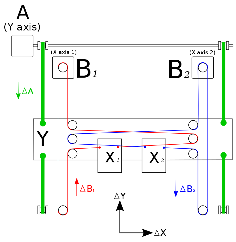
The movement equations are:
ΔX1 = ΔB1
ΔX2 = ΔB2
ΔY = ΔA + ΔB1 + ΔB2So in order to move the gantry (= Y axis), all three motors have to turn synchronously.
My problem is that when the gantry changes direction, the X carriage (either one) moves instantly about 0.2mm in the X direction and -0.2mm once the gantry changes direction again. This leads to rough surfaces on the models I print as well as dimensional inaccuracies.
I have already tried adjusting the tension of the belts but this does not have any influence on the value (still about 0.2mm), whether they're a little too loose or too tight.
The belts for Motor B1 & B2 are pretty long, about 2.5m each. The A belts are about 1.2m each. I wonder if this is unavoidable backlash from long belts? Or are the belts just crappy? They're glass fiber-reinforced GT2 belts from Reprap-World. I also bought the metal pulleys from there.
One thing I also noticed is that the shaft moving the gantry and connected to Motor A, is not 100% straight. This means that the pulleys moving the gantry, are doing slightly eccentric rotations. However if this was the problem, wouldn't this lead to constant twitches of the carriage during long movements? But the twitches only happen upon each change of direction.
I also checked the parallelism of the belts and well... for the naked eye they seem to be parallel, then again it's hard to get 2.5m long belts perfectly parallel. Is there a guide on how to check this easily?
Any other ideas? I am thankful for any tips!
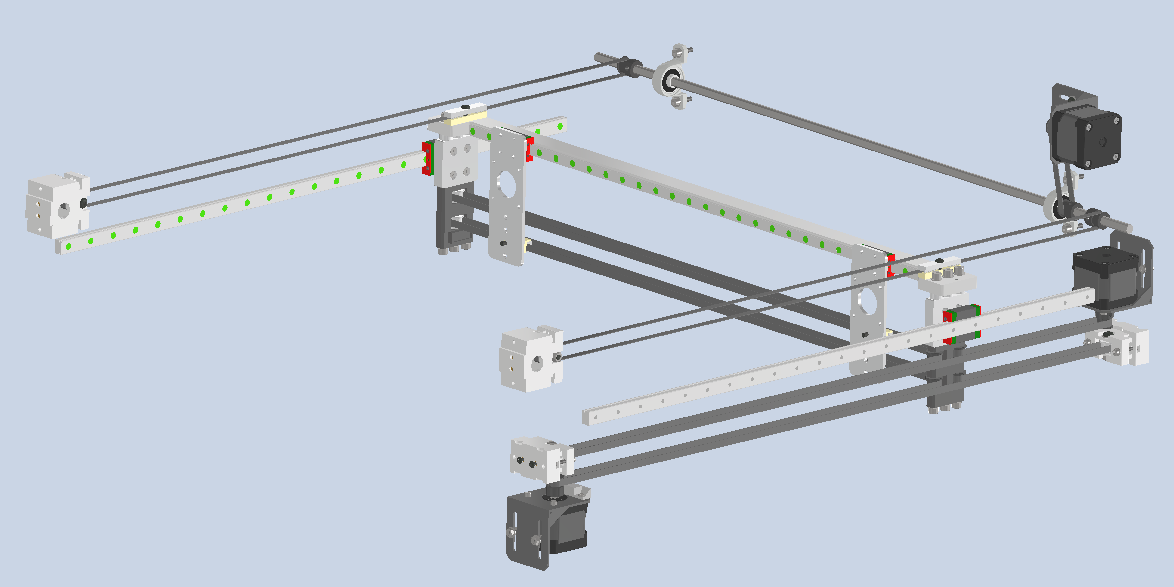
Here's a screenshot of the CAD:
Edit: One thing I forgot to mention: When the motors are powered, I am still able to move the carriage by hand by about 0.2mm as well. I think this shouldn't be possible.
-
@techni I have similar setup with 2 Y motors, and had kind of the same problem, in the end it was bad motor driver, New duet board and it is solved.
Your last edit clearly shows you got mechanical problem .
One more thing why both your X and U axis are on the same side? It would be better to have them on diferent sides as per your first schemeMuldex IDEX Duet2+Duex5
Custom CoreXY 600x400 Hemera , Duet3+Toolboard+1HCL closed loop
Sapphire Pro with Duet2, with closed-loop motors
custom high temp E3D tool changer with Duet2+Duex -
@techni
I guess, you've already checked the setscrews in the pulleys? -
@martin7404 I also think it's a mechanical problem but I am having trouble to find the source. For now, I am gonne replace the shaft with 2 motors connected in series. Even if this does not solve this problem, at least it's one less source of noise and vibrations. It seems to be quite hard to find straight shafts on the market. And then there's the chance that they get bent during shipment, too.
@martin7404 said in Issues with Haq XY/Markforged kinematics:
One more thing why both your X and U axis are on the same side? It would be better to have them on diferent sides as per your first scheme
It's mostly because of the frame and the available space for motors. I think if the upper belts do their job and keep the gantry in check, I don't have to worry about racking issues or similar with this configuration.
@o_lampe said in Issues with Haq XY/Markforged kinematics:
I guess, you've already checked the setscrews in the pulleys?
Yes, they're all very tight. One thing I did notice is that it's quite difficult to tension the short belt which drives the shaft. In the past, the twitch was much larger (like ~1mm) and then I tightened the small belt and it reduced to 0.2mm. Now the belt is so tight I fear that it's bending the shaft. But I can't untighten it or tighten it even more.
Hence, I hope removing the shaft will solve a few problems, maybe this one too. Any other ideas are still welcome though.
-
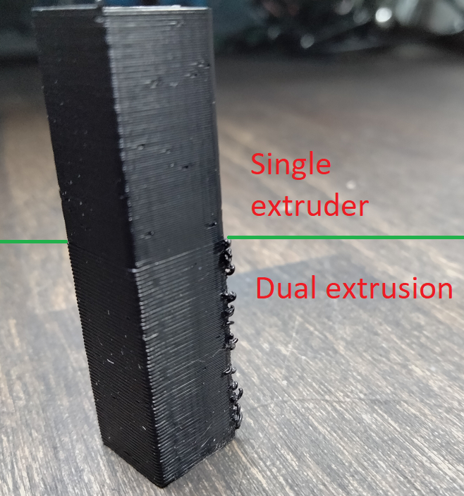
I've had some problems with print quality (with a dual markforged printer). I haven't found solution (however I know that there was some issues with bad temperature control and printed parts giving in sightly) and to my case and I'm planning to change back to single extruder. In my case the print quality is only bad with dual extrusion but not with single extrusion.
3D-printer part collector || https://grabcad.com/eetu-4/models
-
You should not be able to move the gantry when the motors are powered - something is slipping, I would think.
You mentioned putting two steppers in series - does your controller have an unused driver that you could make use of, instead of putting both stepper on one?
I designed and build a single extruder printer using the Markforged system and it works well.
It uses 9mm belts for all axes - I don't know if they are part of the reason it works well but it seemed like a good idea.
-
@fcwilt said in Issues with Haq XY/Markforged kinematics:
You mentioned putting two steppers in series - does your controller have an unused driver that you could make use of, instead of putting both stepper on one?
Does this make a difference? I am sure the Duet 3 can handle two Nema 17 motors on one driver (2x 1.7A). I think the maximum is about 6A for the Duet 3. Or is there an advantage when using two seperate drivers?
-
@techni said in Issues with Haq XY/Markforged kinematics:
@fcwilt said in Issues with Haq XY/Markforged kinematics:
You mentioned putting two steppers in series - does your controller have an unused driver that you could make use of, instead of putting both stepper on one?
Does this make a difference? I am sure the Duet 3 can handle two Nema 17 motors on one driver (2x 1.7A). I think the maximum is about 6A for the Duet 3. Or is there an advantage when using two seperate drivers?
With one stepper the way you have it once the pulley adjustments are made the gantry is likely to stay perpendicular to the Y rails as it should.
With two steppers on one driver you may have to adjust things on occasion since there is nothing really to keep the steppers exactly in sync.
With two steppers on two drivers, if you equip each Y axis with an endstop sensor, any needed adjustment would occur whenever you homed the Y axis. This assumes you could tweak the position of the endstop sensors to get just the right trigger point OR tweaked the Y positions in the homing gcode.
-
@techni said in Issues with Haq XY/Markforged kinematics:
Does this make a difference? I am sure the Duet 3 can handle two Nema 17 motors on one driver (2x 1.7A). I think the maximum is about 6A
Putting them in series doesn't double the current, but halfes the max. achievable speed.
Prusas used to have two Z motors (in series), but there the max. speed is no issue.
If you want to use only one driver, put the motors in parallel. -
Thanks for the help so far guys, appreciate it! I finally found time and I think I owe you an update.
I replaced the shaft with two independent motors connected to two drivers and installed another limit switch so that each end of the gantry now has one. This solved many problems including the mentioned twitch of the carriage when the gantry changed direction (or at least it reduced it to 0.01mm compared to 0.2mm before).
Now an issue which remains is that the carriage moves very slightly in the X direction when I want to move only the Y axis. I did some measurements with a dial gauge mounted to the gantry and this is the pattern I got (it's pretty consistent but not exactly linear):
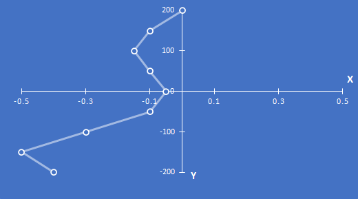
(All units in [mm])
As you can see, the X axis also moves about 0.5mm when I move the Y axis 400mm. On some locations more than on others. Interesting thing is: it's almost exactly the same pattern & values for the second carriage.
Any idea what could cause this?
-
@techni I would guess that your belt paths aren’t straight where they need to be.
Ian