Hello everybody
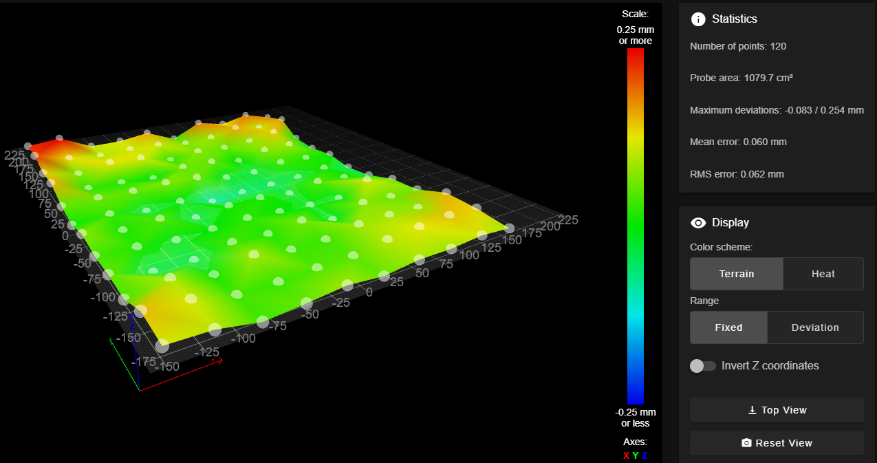
I am looking for an automated solution to align the nozzle of both print heads of an IDEX printer in X & Y direction where the print heads determine their offsets themselves with the help of a probe, as shown here:
I have already found a couple of automated solutions like:
nudge by zruncho3d shown in the picture above (https://github.com/zruncho3d/nudge)
NozzleAlign Ball Probe by viesturz (https://github.com/viesturz/NozzleAlign)
There are also some manual solutions like:
TAMV by Danal (https://github.com/HaythamB/TAMV?tab=readme-ov-file)
XY calibration tool by EmberPrototypes (https://www.emberprototypes.com/products/cxc)
I have tested the calibration tool by EmberPrototypes and it works fine (much better than the calibration prints) but it's far from automated.
I wish to use either the nudge or the ball probe but both probes provide the code only for Klipper.
I wonder if anyone has managed to get them to work under RRF or if there exists another similar solution for Duet users?
Cheers
TechNi
Edit: After further digging, maybe this can be coded relatively simply with M558 & M585?