Huanyang VFD 2,2kw Water Cooled Spindle to D3MB6HCv1 mainboard
-
Greetings,
I finished connecting my Huanyang VFD 2,2kw 110v Water Cooled Spindle to my D3MB6HCv1 mainboard. Wanted to post this info for others that wanted to do the same.
Searched this forum and started with this post by Catalin_RO 26 Jun 2018, 13:54 - https://forum.duet3d.com/topic/4762/vfd-spindle-drive-0-10v-output/6
I bought the module on Amazon (currently unavailable, but there are other similar modules available, make sure it is a 0-10V) KNACRO PWM to 0-10V Conversion Module Digital to Analog Module PLC Industrial Interface Conversion Module.
Wired the module using information from an Openbuilds post here - https://openbuilds.com/threads/workbee-cnc-w-duet2-and-chinese-spindle-control.14004/
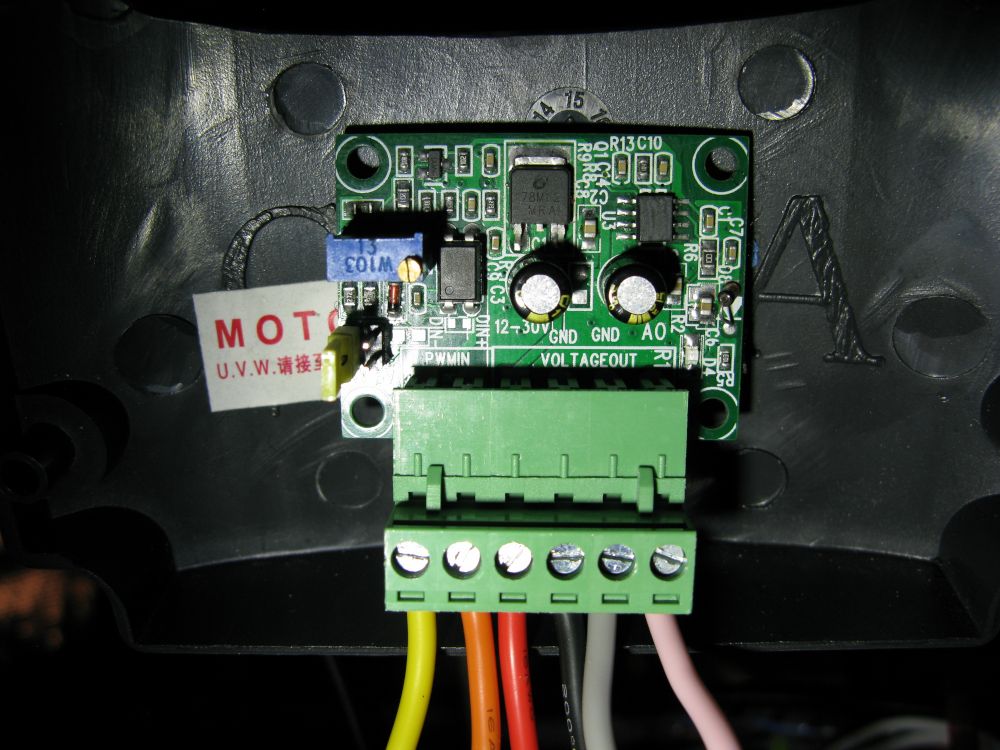
The module needs external power and will operate at 5v and 24v. There is a white jumper on the side that can be changed for the voltage you have available. The black and red wires in the image below are from the 24v power supply that powers the mainboard.
The orange and yellow wires are connected to the mainboard on the - 2-pin JST VH or compatible connectors OUT_1 thru OUT_3 pins normally used for extruders, heaters, and fans. I used the "OUT_1" connection. With this 2 pin connection, OUT_1 pin connects to the yellow wire and the V_FUSED connects to the orange wire.
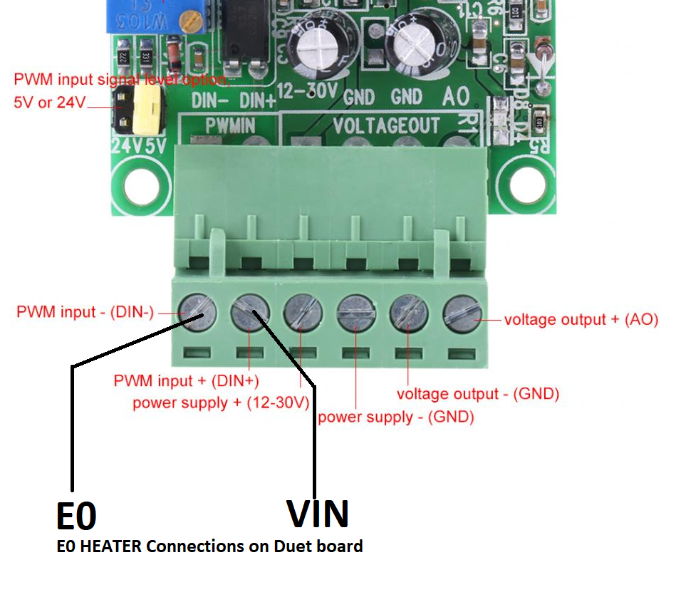
I found this image on the Openbuilds site. I do not know if it is accurate. I could not find a schematic of the module and this image was helpful.
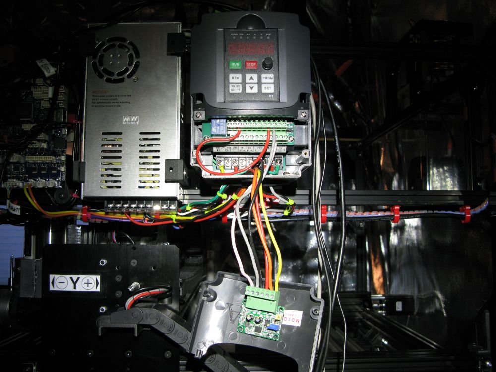
The grey and pink wires from the module connect to the VFD control circuit terminals at the ACM (grey) and the VI (pink) terminals. The red wire is a jumper to keep the VFD in an 'always on' state using DCM and FOR terminals, (WARNING: I do not know if this will cause some unforeseeable problem with the VFD, use at your own risk) otherwise you will need to use another module (two total) and use another pin on the mainboard to turn the spindle on when the M3 is issued. See M453 for more info: https://duet3d.dozuki.com/Wiki/Gcode#Section_M453_in_RepRapFirmware_3_0_and_3_1_x
Next, you will need to program the VFD on the main panel. The following information was taken from: https://openbuilds.com/threads/workbee-cnc-w-duet2-and-chinese-spindle-control.14004/
-
PD001 from 0 to 1 to change spindle on/off from "operator" control to "external" control.
-
PD002 was already set to 1, which is "external" control, but until you switch the jumper, the "external" is the potentiometer on the control panel. Once you move the jumper to the left, it will use the pins.
-
PD070 from 1 to 0 to change the input voltage it's looking for from 0-5v to 0-10v. Before I changed this, the spindle speed was double what I was sending. i.e. I'd send M3 S12000 and the spindle would go to 24000RPM.

The module is velcro'd to the inside of the hatch and out of the way when it's buttoned up.
The config.g needs to be reconfigured to use the "OUT_1" pin on the mainboard.
; Configuration file for Duet 3 (firmware version 3)
; executed by the firmware on start-up
;
; generated by RepRapFirmware Configuration Tool v3.1.4 on Wed Jul 29 2020 15:25:39 GMT-0700 (Pacific Daylight Time)

; General preferences
M453			       					; CNC Mode
G90                            			; send absolute coordinates...
M83                            			; ...but relative extruder moves
M550 P"Duet 3"                 			; set printer name

; Drives
M569 P0.2 S0                   			; X 0.2 physical drive goes backwards
M569 P0.0 S0                			; Y-R 0.0 physical drive goes backwards
M569 P0.1 S0                   			; Y-L 0.1 physical drive goes backwards
M569 P0.3 S1                   			; Z 0.3 physical drive goes forwards
M584 X0.2 Y0.0:0.1 Z0.3 E0.4:0.5:0.6 	; set drive mapping
M350 X16 Y16 Z16 U16 I1        			; configure microstepping with interpolation U=dummy Y axis
M92 X400.00 Y400.00 Z400.00      		; set steps per mm
M566 X900.00 Y900.00 Z12.00    			; set maximum instantaneous speed changes (mm/min)
M203 X2000.00 Y2000.00 Z1000.00 		; set maximum speeds (mm/min)
M201 X500.00 Y500.00 Z20.00    			; set accelerations (mm/s^2)
M906 X3000 Y2500 Z3000 I30     			; set motor currents (mA) and motor idle factor in per cent
M84 S30                        			; Set idle timeout

; Axis Limits
M208 X0 Y0 Z0 S1                		; set axis minima
M208 X500 Y375 Z60 S0          	    	; set axis maxima

; Endstops
M574 X2 S1 P"!^io0.in"         			; configure active-high endstop for high end on X via pin !^io0.in
M574 Y1 S1 P"!^io1.in"         			; configure active-high endstop for low end on Y via pin !^io1.in
M574 Z2 S1 P"!^io2.in"         			; configure active-high endstop for high end on Z via pin !^io2.in

; Z-Probe
M558 P5 c"!^io7.in" H5 F120 R1 T300     ; Z probe switch type, probe recovery 1s probe speed and travel speed
M557 X15:215 Y15:195 S20       			; define mesh grid

; Fans
M950 F0 C"out7" Q500           			; create fan 0 on pin out7 and set its frequency
M106 P0 S1 H-1                 			; set fan 0 value. Thermostatic control is turned off
M950 F1 C"out8" Q500           			; create fan 1 on pin out8 and set its frequency
M106 P1 S1 H-1                 			; set fan 1 value. Thermostatic control is turned off

; Tools
M563 S"XYZ-Probe" P1                    ; define XYZ Touch Probe tool 1
M563 P0 S"Spindle"                      ; define tool 0
G10 P0 X0 Y0 Z0                         ; set tool 0 axis offsets
G10 P0 R0 S0                            ; set initial tool 0 active and standby temp to 0C

; Custom settings are not defined
M564 S1 H1                              ; disable jog commands when not homed
M501                                    ; load stored parameters

; CNC
M453 S0 C"out1" R24000 Q100 T0          ; set to CNC mode using tool 0 pin=1 max RPM 24000 PWM frequency 100hz
Lines 47-49 and line 57 need to be added. I'm not sure if lines 48 and 49 are needed concerning the G10 parameters for the M563 that defines the spindle as tool 0.
M563 P0 S"Spindle" defines the spindel as tool 0.
M453 S0 C"out1" R24000 Q100 T0 sets up the tool and needs to come after the M563 that defines the spindel. T0 is optional and aids the DWC in monitoring the tool.To test the setup, enter M3 S500 on the DWC console to turn the spindle @ 500 RPM and all should be well. Enter M5 to turn it off.
If anyone needs help, post a reply and I'll try to help out. Otherwise, somone with more experience from Duet3D will come to your aid.
-
-
good write up but I have a question and an enhancement for you.
First off, the duet 3 doesn't need the PWM converter as it has a 0-5v VFD header. As the huanyang supports both 0-5v and 0-10v control, why didn't you use that? Removes any middle components and cleans the installation up.
In RRF3, an enable pin is able to specified. This would allow you to remove the wire from between the forward and DCM terminals.
To do so, you would first need to connect DCM to the 0v line on the PSU supplying the duet. This just ties the ground together. You then connect the "For" line to the ground pin of an out connecter on the duet. Any of the heater or fan pins would work.
You would then modify the M453 command toM453 S0 C"out1+out2" R24000 Q100 T0Assuming out2 is used for the enable side. This means you reduce the risk of the spindle operating accidently.
This is how I have my spindle wired up to a non duet 3 (but still RRF) board.Owns various duet boards and is the main wiki maintainer for the Teamgloomy LPC/STM32 port of RRF. Assume I'm running whatever the latest beta/stable build is
-
Does the Duet3 PWM output need filtering to get an analogue signal for the VFD or will the Huanyang work from the PWM signal directly?
-
It should work directly with it.
If I get time, I might be able to run a test today -
This post is deleted! -
@max3d Thanks for this. Can you explain a bit more about the red wire you have used? Is it just connecting DCM and FOR or is there something else there?
Many thanks,
Mark
-
@cjm said in Huanyang VFD 2,2kw Water Cooled Spindle to D3MB6HCv1 mainboard:
Does the Duet3 PWM output need filtering to get an analogue signal for the VFD or will the Huanyang work from the PWM signal directly?
If the spindle controller needs an analog signal then you do need to convert it. In any case, I recommend using the converter because it provides optical isolation between the Duet and the spindle controller. However, instead of using an OUT pin to drive the converter, you could use the Laser/VFD output and set the jumper on the converter to 5V.
Duet WiFi hardware designer and firmware engineer
Please do not ask me for Duet support via PM or email, use the forum
http://www.escher3d.com, https://miscsolutions.wordpress.com -
@dc42 Many thanks for the answer.
As it happens, I ended up making an opto-isolated board to drive my VFD (very similar to the Huanyang) with filtering for VFD speed and an Arduino to convert the VFD's tacho voltage to a variable frequency logic level signal that drives the Duet's Fan0 RPM input:
https://forum.duet3d.com/topic/19968/duet-integration-with-an-askpower-a131-vfd/4?_=1623690078188 -
@mdhazell Greetings. Change PD001 from 0 to 1 to change spindle on/off from "operator" control to "external" control on the VFD control panel. You will need to power up the VFD manually before a job. I can see where this might cause some confusion because you can set the VFD up to power up and down automatically. The DCM and FOR terminals are used for that.
Good luck ...
-
@jay_s_uk Thanks for the reply. I did not have my email notification turned on so I missed your reply.
I used a converter to protect the mainboard. I followed a suggestion from one of the administrators from another post. At the time they did not have enough information on the Huanyang VFD and the converter would be an added safety measure.
Great addition to the post. If anyone wants to nix the converter they can use your method.
-
@max3d Thanks for this. So, you mention the red wire is a jumper between DCM and FOR, is it just used to connect the two together?
Thanks,
Mark -
@mdhazell Yup, you got it. The red wire connects the two terminals together.
-
@max3d many thanks
-
@max3d said in Huanyang VFD 2,2kw Water Cooled Spindle to D3MB6HCv1 mainboard:
To test the setup, enter M3 S500 on the DWC console to turn the spindle @ 500 RPM and all should be well. Enter M5 to turn it off.
But after installing the red wire jumper the spindle starts rotating after its powered and doesn't stop by M5 and looks , like doesn't want rotate slower than ~500rpm
Do I need to connect the second module to another port to control On/Off function?I'm using Duet 3 MB6HC Firmware 3.4.1
Any help will be very appreciable !; Configuration file for Duet 3 (firmware version 3.3) ; executed by the firmware on start-up ; ; generated by RepRapFirmware Configuration Tool v3.3.10 on Thu Jul 21 2022 ; General preferences ;M575 P1 S1 B57600 ; enable support for PanelDue G90 ; send absolute coordinates... M83 ; ...but relative extruder moves M550 P"M1 Candy" ; set printer name M669 ;K1 ; select CoreXY mode ; Network M552 S1 M586 P0 S1 ; enable HTTP M586 P1 S0 ; disable FTP M586 P2 S0 ; disable Telnet ; Drives M569 P0.0 S0 ; physical drive 0.0 goes forwards M569 P0.1 S0 ; physical drive 0.1 goes forwards M569 P0.2 S1 ; physical drive 0.2 goes forwards M569 P0.3 S0 ; physical drive 0.3 goes forwards M569 P0.4 S1 ; physical drive 0.3 goes forwards M584 X0.0 Y0.1:0.2 Z0.3 E0.4 ; set drive mapping M350 X16 Y16:16 Z16 E16 I1 ; configure microstepping with interpolation M92 X223.00 Y223.00:223.00 Z316.00 E420.00 ; set steps per mm M566 X900.00 Y780.00:780.00 Z420.00 E120.00 ; set maximum instantaneous speed changes (mm/min) M203 X6000.00 Y4800.00:4800.00 Z1000.00 E1200.00 ; set maximum speeds (mm/min) M201 X500.00 Y500.00:500.00 Z350.00 E250.00 ; set accelerations (mm/s^2) M906 X4000 Y4000:4000 Z4000 E800 I30 ; set motor currents (mA) and motor idle factor in per cent M84 S30 ; Set idle timeout ; Axis Limits M208 X0 Y0 Z0 S1 ; set axis minima M208 X2000 Y3000 Z200 S0 ; set axis maxima ; Endstops M574 X1 S1 P"io0.in" ; configure switch-type (e.g. microswitch) endstop for low end on X via pin io0.in M574 Y1 S1 P"io1.in" ; configure switch-type (e.g. microswitch) endstop for low end on Y via pin io1.in M574 Z1 S1 P"io2.in" ; configure switch-type (e.g. microswitch) endstop for low end on Z via pin io2.in ; Z-Probe M558 P0 H5 F120 T6000 ; disable Z probe but set dive height, probe speed and travel speed M557 X15:215 Y15:195 S20 ; define mesh grid ; Heaters ; Fans M950 F0 C"out4" Q500 ; create fan 0 on pin out4 and set its frequency M106 P0 S1 H-1 ; set fan 0 value. Thermostatic control is turned off ; Tools M950 R0 J1 C"out1" Q100 L0:24000 ; Create spindle index 0 with M563 P0 R0 S"Spindle" ; define tool 0 G10 P0 X0 Y0 Z0 ; set tool 0 axis offsets G10 P0 R0 S0 ; set initial tool 0 active and standby temperatures to 0C ; Custom settings are not defined M453 S0 C"out1" R24000 Q100 T0 -
@allsirius You may want to start a new thread for your issue.
-
 undefined AllSirius referenced this topic
-
undefined AllSirius referenced this topic