Prevent fan burst during startup on RRF 3.2.2
-
It seems like the fan 2 is turned on briefly every time I restart the printer. I tried remapping to other fan ports and it does the same thing.
I set all my fans to be off in my config.g file (see below). I have a Berd Air pump connected to the Fan 2 port. However, whenever I start the printer or hit the stop button, the fan rotates for a brief 100 milliseconds or so. For regular fans, it may not be an issue, but with the Berd Air pump, it very jolting and can reduce the life of the pump.
I recall DC42 mentioning the Fan1 hardware port is designed to turn the fan on by default. However, for Fan2 port, it seems to do the same thing.
Is there a config.g setting to prevent this from happening? I even included a "B0" parameter into the M106 command and it has no affect.
I recently migrated to RRF 3.2.2 and this is one of the issues I have not been able to fix from RRF2. The other issue is that I get a random error message 4, 241, 246, etc when I hit the STOP button on the panelDue. The error message are random and every time I press stop, I get a new message.
; ---------------------------- Fan Settings ------------------------------------
; Fan mapping
M950 F0 C"fan0" Q500 ; Map Fan 0 to P0
M950 F1 C"fan1" Q500 ; Map Fan 1 to P1
M950 F2 C"fan2" Q500 ; Map Fan 2 to P2; Fan Settings
M106 P0 B0 S0 H-1 ; Set fan 0 value, Thermostatic control is turned off
M106 P1 B0 S0 H-1 ; Set fan 1 value, Thermostatic control is turned off
M106 P2 B0 S0 H-1 ; Set fan 2 value, Thermostatic control is turned off; ---------------------------- Tool Settings ------------------------------------
M563 P0 D0 H1 ; Define tool 0
G10 P0 X0 Y0 Z0 ; Set tool 0 axis offsets
G10 P0 R175 S190 ; Set initial tool 0 active and standby temperatures. S= active R= standby -
@shadowx
AFAIK, it already happens before RRF configures the MPU pins. It's a default thing of the MPU, I guess. -
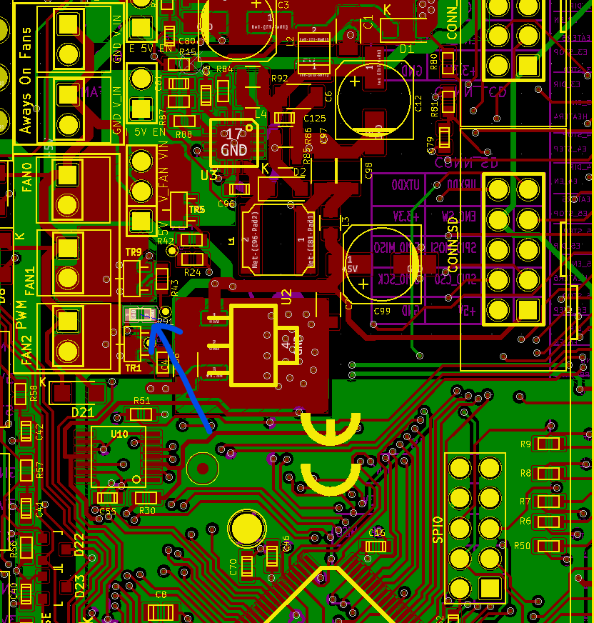
@shadowx, Fan 2 should not turn on by default. If the board is a Duet WiFi or Ethernet, check that resistor R91 is present on your board.
-
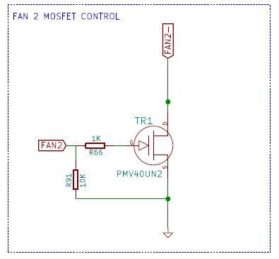
@dc42 I looked at the PWB and the R91 is installed. I checked the value with an SMT probe to measure the resistor value. The measurement is 10K in resistance. I measured R24 also and it was 10K also. The R66 was 1K in resistance. It seems to match the schematic values below.
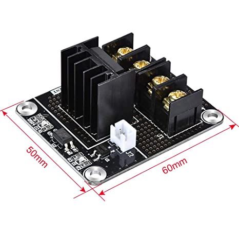
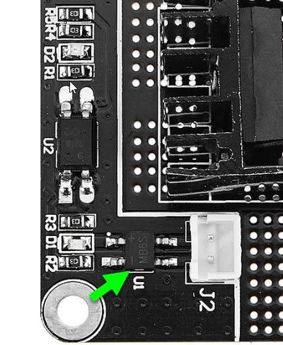
I have revision 1.0 of the board (DuetWifi 2). I also use an external BIQU 3D0109 board to connect from the fan port to my Berd Air pump. The MOSFET board has opto-isolators on the input connections that is used to connect to the Fan2 output. I haven't had issues with this setup until this upgrade to RRF3.
I haven't hooked up the Fan 2 output to my digital storage oscilloscope, but I can capture a measurement of the output signal if you need it.
-
@shadowx please post your config.g file.
Does fan0 show similar behaviour?
Duet WiFi hardware designer and firmware engineer
Please do not ask me for Duet support via PM or email, use the forum
http://www.escher3d.com, https://miscsolutions.wordpress.com -
@dc42
No. It seems like the Fan0 acts normal. When the machine is turned on, the fan does not turn on and quickly turn off. I was able to manually turn fan0 on with the web interface to make sure it is running properly.The issue only affects Fan1 and Fan2. Only those two fan connections blip on quicky and shuts off in about half a second.
Here is my config.g file (not very pretty). I have a delta printer.
; Configuration file for Duet WiFi
; executed by the firmware on start-up

; -------------------------------- General Settings ------------------------------------
M111 S0 		; Debugging off
G21 			; Work in millimeters
G90 			; Send absolute coordinates...
M83 			; ...but relative extruder moves
M555 P1 		; Set firmware compatibility to look like RepRapFirmare

; ---------------------------- Printer Bed Settings ------------------------------------
; Rod length settings for reference:
; L = Ideal Length / Measured_length * Original Delta Rod Length
; Larger Number = Smaller part size
; Smaller Number = Larger part size

; Delta Radius setting for reference:
; Lower number  - Middle get looser
; Higher number - Middle get tighter

; MANUAL CALIBRATION DATA
M665 L438.000 R264 H424.75 B150 					; M665 - Set delta radius, diagonal rod length, printable radius and homed height, B = safe printing radius
M666 X0 Y0 Z0								; M666 - Put your endstop adjustments here, or let auto calibration find them

; ---------------------------- Motor and Extruder Settings ------------------------------------
; Motor Settings
M569 P0 S1 								; Drive 0 (S0 = Backwards; S1 = Forwards)  X-Axis
M569 P1 S1 								; Drive 1 (S0 = Backwards; S1 = Forwards)  Y-Axis
M569 P2 S1 								; Drive 2 (S0 = Backwards; S1 = Forwards)  Z-Axis
M569 P3 S0 								; Drive 3 (S0 = Backwards; S1 = Forwards)  Extruder
M350 X16 X16 X16 X16 I1 						; Configure microstepping without interpolation
M906 X1000 Y1000 Z1000 E600 I30 					; Set motor currents (mA) and motor idle factor in per cent
M84 S30 										; Set motor idle timeout

; Acceleration, Jerk and speed
M566 X1000 Y1000 Z900 E170 						; Jerk - Set maximum instantaneous speed changes (mm/min)
M201 X2000 Y2000 Z2000 E200 						; Set accelerations (mm/s^2)
M203 X20000 Y20000 Z20000 E5000 					; Set maximum speeds (mm/min)

; Extruder
M92 X80 Y80 Z80 E2680 							; Set steps per mm; E value is in mm/minute    E2715
M572 D0 S0.18  								; Extruder pressure advance

; ---------------------------- End Stops ------------------------------------
M574 X2 S1 P"xstop" 							; Configure active-high endstop for high end on X via pin xstop
M574 Y2 S1 P"ystop" 							; Configure active-high endstop for high end on Y via pin ystop
M574 Z2 S1 P"zstop" 							; Configure active-high endstop for high end on Z via pin zstop


; ---------------------------- Bed Level and Probe Settings ------------------------------------
; Grid Mesh
M557 X5:205 Y5:165 S20 							; Define mesh grid

;Precision Piezo Settings
M558 P1 C"zprobe.in" H1 F400 T10000 R0.5 S0.1 A6  			; R- Recoverty Time before probing start; A - max times to probe each point; S - tolerance with each probe
G31 P500 X0 Y0 Z0.08 							; Set Z probe trigger value, offset and trigger height  (increasing z makes nozzle go lower)


; ---------------------------- Motor and Extruder Settings ------------------------------------
; Bed Heater
M308 S0 P"bed_temp" Y"thermistor" T100000 B3950 R4700 L0 H9		; Define bed temperature sensor
M950 H0 C"bed_heat" T0 							; Heater 0 uses the bed_heat pin, sensor 0
M307 H0 A366.5 C667.4 D11.7 S1.00 V0.0 B1 				; Bed heater setting
M140 H0									; Map heated bed to heater 0
M143 S80								; Set maximum heater temperature to 80C
M570 S200 								; Set maximum heating time to 200s

; Extruder Heater
M308 S1 P"spi.cs1" Y"rtd-max31865" F20					; Define E0 temperature sensor
M950 H1 C"e0heat" T1 							; Heater 1 uses the e0heat pin and sensor 1
M307 H1 A347.2 C180.2 D4.8 S1.00 V12.0 B0 				; Hot End heater setting

; ---------------------------- Fan Settings ------------------------------------
; Fan mapping
M950 F0 C"fan0" Q500			; Map Fan 0 to P0
M950 F1 C"fan1" Q500			; Map Fan 1 to P1
M950 F2 C"fan2" Q500			; Map Fan 2 to P2

; Fan Settings
M106 P0 B0 S0 H-1 			; Set fan 0 value, Thermostatic control is turned off
M106 P1 B0 S0 H-1 			; Set fan 1 value, Thermostatic control is turned off
M106 P2 B0 S0 H-1 			; Set fan 2 value, Thermostatic control is turned off

; ---------------------------- Tool Settings ------------------------------------
M563 P0 D0 H1 				; Define tool 0
G10 P0 X0 Y0 Z0 			; Set tool 0 axis offsets
G10 P0 R175 S190			; Set initial tool 0 active and standby temperatures.  R= standby S= active

; ---------------------------- Network Settings ------------------------------------
M550 PDuetWifi 				; Set machine name
M552 S1 				; Enable network and acquire dynamic address via DHCP
M575 P1 S1 B57600			; Set the Serial Communication parameters
FYI: The BIQU MOS Driver has a MB6S full bridge rectifier on the input connection, so the fan wire polarity should not make a difference. The U2 is the opto-isolator chip.
-
@dc42 Is there a way to fix this problem in the config.g file or do I have to just remove the resistor on the other fan ports?
-
@shadowx Fan 1 is intended to be on by default, because we intend you to use it as the hot end heatsink cooling fan. The idea is that if the hot end is hot and you reset without the SD card present, or you upload new firmware, the fan will be on by default.
Fan 2 should not blip at startup. Resistor R91 should hold the gate low (resisting the pullup resistor in the MCU, which has a resistance between 50K and 150K) until the firmware sets it low.
If this still happens with firmware 3.3 then I will test whether it happens on my bench system.
If you have any spare heater ports on your Duet, you can use those to drive fans.
Duet WiFi hardware designer and firmware engineer
Please do not ask me for Duet support via PM or email, use the forum
http://www.escher3d.com, https://miscsolutions.wordpress.com -
@dc42 Thanks for letting me know. My Fan0 is fine, but the Fan1 and Fan2 blips. For now, I will use Fan0 port.
-
@shadowx have you tried firmware 3.3 yet?
Duet WiFi hardware designer and firmware engineer
Please do not ask me for Duet support via PM or email, use the forum
http://www.escher3d.com, https://miscsolutions.wordpress.com -
@dc42 I just installed RRF 3.3 and it seems to fix the problem. The Fan1 turns on for a brief second as designed. The Fan0 and Fan2 does not come on for a brief second when I reset the board. It looks good!
I still get the random command error messages as described by the link below. This only happens when I press the "STOP" button on the PanelDue. When I click on the "Emergency Stop" button on the web interface, the error message does not pop up.
I rechecked my wires to the PanelDue. It is only less than a foot long and is fully shielded the whole length other than the connector locations.
https://forum.duet3d.com/topic/17990/rrf3-paneldue-stop-function-results-in-a-false-error-message
Thanks for your help!
-
@shadowx that's been fixed in 3.3.0 I believe
-
@jay_s_uk I am running 3.3 right now and the error is still there. My PanelDue firmware is 1.24 and its the latest for version 1.1 of the PanelDue hardware.
-
I wonder if the PanelDue's firmware for the DoEmergencyStop() delay code: "Delay(1000)" after the M999 command needs to be increased to prevent the signal overlap that caused the command errors.
Probably not the most elegant solution, but if it works, it works.
static void DoEmergencyStop() { // We send M112 for the benefit of old firmware, and F0 0F (an invalid UTF8 sequence) for new firmware SerialIo::Sendf("M112 ;" "\xF0" "\x0F" "\n"); TouchBeep(); // needed when we are called from ProcessTouchOutsidePopup Delay(1000); SerialIo::Sendf("M999\n"); Delay(1000); Reconnect(); } -
@shadowx I suggest upgrading the paneldue to 3.2.11 to see if it can be replicated
-
@jay_s_uk I can't update to 3.2.11. Anything greater than 1.24 requires more memory and the v1.1 of the panel due has limited memory space.
Due to the lack of RAM this build will not run on version 1 or early version 2 PanelDue boards that use the ATSAM3S2B chip. Version 1.0, 1.1 and earlier v2 PanelDue: ATSAM3S2B processor (64MHz, 32kb RAM, 128kB flash) - these are the ones that the new firmware probably won't run on. -
@shadowx sorry. Didn't realise you had an older one