Hotend stalling during movement and baby stepping issue
-
@jay_s_uk so the fault is still there both stalling just at a faster speed!, bed to 100 then carried out my bed levelling macro which is -
G28
G32
G32
G29 S2
G29 S0I then carried out a test file I made that moves the hot end around which is just -
G28 XY
G0 X100 Y100 F10000
G3 X100 Y100 I25
G3 X100 Y100 I25
G0 X10 Y10
G0 X100 Y100 F10000
G2 X100 Y100 I25
G2 X100 Y100 I25
G0 X10 Y10
(repeated over and over)unfortunately I have to go to work now and wont be able to test more till the morning, if you have any ideas I'm all ears and thankyou for your help so far
")
Jim
-
@jumpedwithbothfeet it may be easier for us to help if you post your config.g file.
As well as motor current being too low, another common cause of motors stalling is acceleration set too high. Acceleration is controlled by the M201 command in config.g.
Duet WiFi hardware designer and firmware engineer
Please do not ask me for Duet support via PM or email, use the forum
http://www.escher3d.com, https://miscsolutions.wordpress.com -
@dc42 sorry I did attach it to the first post but it would of made more sense putting it at the top apologies so here is a fresh copy -
I have not played with the acceleration settings at all in config.g as my machine is nearly always in a state of flux! so I imagine they are stock settings for the firmware still
; Configuration file for Duet 3 (firmware version 3) ; executed by the firmware on start-up ; ; generated by RepRapFirmware Configuration Tool v2.1.8 on Mon Apr 06 2020 18:55:28 GMT+0100 (British Summer Time) ; General preferences G90 ; send absolute coordinates... M83 ; ...but relative extruder moves M550 P"Duet 3" ; set printer name M669 K1 ; select CoreXY mode M575 P1 S1 B57600 ; paneldue ; Drives M569 P0.0 S0 ; physical drive 0.0 goes backwards M569 P0.1 S0 ; physical drive 0.1 goes forwards M569 P0.2 S0 ; physical drive 0.2 goes backwards M569 P0.3 S0 ; physical drive 0.3 goes backwards M569 P0.4 S0 ; physical drive 0.4 goes backwards M569 P0.5 S1 ; physical drive 0.4 goes backwards M584 X0.3 Y0.5 Z0.0:0.1:0.2 E0.4 ; set drive mapping M671 X0:175:284 Y0:330:0 S10 ; Z leadscrews locations M350 X16 Y16 Z16 E16 I1 ; configure microstepping with interpolation M92 X80.00 Y80.00 Z800.00 E812.6 ; set steps per mm M566 X900.00 Y900.00 Z12.00 E120.00 ; set maximum instantaneous speed changes (mm/min) M203 X30000.00 Y30000.00 Z600.00 E3000.00 ; set maximum speeds (mm/min) M201 X500.00 Y500.00 Z20 E5000.00 ; set accelerations (mm/s^2) M906 X1300 Y1300 Z900 E900 I30 ; set motor currents (mA) and motor idle factor in per cent M84 S30 ; Set idle timeout ; Axis Limits M208 X0 Y0 Z0 S1 ; set axis minima M208 X340 Y330 Z268 S0 ; set axis maxima ; Endstops M574 X1 S1 P"io4.in" ; configure active-high endstop for low end on X via pin io4.in M574 Y1 S1 P"io5.in" ; configure active-high endstop for low end on Y via pin io5.in M574 Z1 S2 ; configure Z-probe endstop for low end on Z ; Z-Probe M950 S0 C"io7.out" ; create servo pin 0 for Mini IR M558 P8 C"io7.in" H5 F120 T6000 R0.75 ; set Z probe type to Mini IR and the dive height + speeds G31 P500 X0 Y0 Z1.641 ; set Z probe trigger value, offset and trigger height M557 X50:320 Y40:300 S45:52 ; define mesh grid ; Heaters M308 S0 P"temp0" Y"thermistor" T98801 B4185 ; configure sensor 0 as thermistor on pin temp0 M950 H0 C"out0" T0 ; create bed heater output on out0 and map it to sensor 0 M143 H0 S130 ; set temperature limit for heater 0 to 120C M307 H0 B0 S1.00 ; disable bang-bang mode for the bed heater and set PWM limit M140 H0 ; map heated bed to heater 0 M308 S1 P"spi.cs0" Y"rtd-max31865" ; define temperature sensor number 1 as a PT100 on the first port of a temperature daughter M950 H1 C"out1" T1 ; create nozzle heater output on out1 and map it to sensor 1 M143 H1 S350 ; set temperature limit for heater 1 to 350C M307 H1 B0 S1.00 ; disable bang-bang mode for heater and set PWM limit M308 S2 P"mcu-temp" Y"mcu-temp" A"mcu-temp" ; configure sensor 2 as thermistor on pin temp2 M308 S3 P"temp1" Y"thermistor" A"Enclosure temp" T100000 B4725 C7.06e-8 ; configure sensor 3 as thermistor on pin temp1 ; Fans ;M950 F5 C"out9" Q500 ; create fan 0 on pin out4 and set its frequency (parts cooling fan) ;M106 P5 S0 H-1 C"servo" ; set fan 0 value. Thermostatic control is turned off M950 F1 C"!out5+out5.tach" Q500 ; create fan 1 on pin out4 and set its frequency (parts cooling fan) M106 P1 S0 H-1 C"Rear Fan" ; set fan 1 value. Thermostatic control is turned off M950 F2 C"out6" Q500 ; create fan 2 on pin out7 and set its frequency (Rad Fan) M106 P2 S1 H-1 C"Rad Fan" ; set fan 2 value. Thermostatic control is turned off M950 F3 C"out8+out6.tach" ; create fan 3 on pin out5 and set its frequency (Cooling Pump) M106 P3 S1 H-1 C"Cooling Pump" ; set fan 3 value. Thermostatic control is turned off M950 F4 C"out9" Q500 ; create fan 4 on pin out4 and set its frequency (case fan) M106 P4 H2 T25 ; set fan 4 value. Thermostatic control is turned on M950 F0 C"out7" Q500 ; create fan 1 on pin out7 and set its frequency (New parts fan) M106 P0 S0 H-1 C"Air Pump" ; set fan 1 value. Thermostatic control is turned off ;M950 S0 C"out9" ; assign GPIO port 0 to servo port, servo mode ;M280 P0 S5 ; set 80deg servo position on GPIO port 0 ; Tools M563 P0 S"Titan Aqua" D0 H1 F1 ; define tool 0 G10 P0 X0 Y0 Z0 ; set tool 0 axis offsets G10 P0 R0 S0 ; set initial tool 0 active and standby temperatures to 0C ; Custom settings are not defined M912 P0 S-7.9 ;M593 F40.5 ; cancel ringing at 40.5Hz ; Miscellaneous M501 ; load saved parameters from non-volatile memory T0 ; select first tool -
@dc42 or anybody with any ideas for that matter! , I have been repeating the fault over and over both X and Y motors work independently but stall when used together so I cant see it being a mechanical issue so...
could the stepper motors or wiring to them be an issue will one drag down the other if there is some sort of mismatch?
would a board reset/fresh install be beneficial?Thanks Jim
-
Further update to my issue, I've stripped my top end apart, as a correction the motors installed are 17HS15-1504S-X1 (the 5's look like 6's) these are rated at 1.5 amp.
All coils measure approximately 2.3 ohms taking into account lead correction so within spec.
both motor leads tested with no breaks or high resistance found, and the crimps appear secure, one lead measures 102cm and the other 99cm, would 3 cm make any difference given they are running on different drivers?my hot end moves freely on its rails and all my pulleys follow suit, I'm now thinking this is a board or firmware issue, I cant see any burnt or popped components on the board although it is still installed so I cant rule this out yet.
I've run P98 on my config and multiple M122 during faulting and after with nothing I can spot with my limited knowledge, is there any other diagnostic tests I can run?
Regards Jim
-
I don't suppose you could post a video of the problem movement?
It may also be helpful to temporarily setup to run the Duet in standalone mode without the Pi to help isolate the issue.
https://duet3d.dozuki.com/Wiki/Getting_Started_With_Duet_3#Section_Running_in_standalone_mode
-
@phaedrux, Morning well at least it is here
, I've just rebuilt the printer and I believe completely offloaded the 12v and 5v rails and my cooling pump as far as possible, however given that I had little running on either I don't hold much hope, I'm currently trying to get it to fail again!! as soon as it does I'll try and post a video, I'm also just configuring an SD card to run in standalone using the guide in your link so fingers crossed.Cheers Jim
-
@phaedrux, so I thought I was getting somewhere as it has been behaving but I've managed to capture it whilst it's faulting, the first 15 seconds show what it like not faulting -
I have attempted to set up an SD card but I found the guide a little confusing as they sort of reference each other but I will attempt to set it up for standalone again tomorrow I just need to do some more digging in the docs and forum to see what files I actually need on the SD.
here's the config file at time of faulting -
; Configuration file for Duet 3 (firmware version 3)
; executed by the firmware on start-up
;
; generated by RepRapFirmware Configuration Tool v2.1.8 on Mon Apr 06 2020 18:55:28 GMT+0100 (British Summer Time)

; General preferences
G90                                         ; send absolute coordinates...
M83                                         ; ...but relative extruder moves
M550 P"Duet 3"                              ; set printer name
M669 K1                                     ; select CoreXY mode
M575 P1 S1 B57600                           ; paneldue

; Drives
M569 P0.0 S0                                ; physical drive 0.0 goes backwards
M569 P0.1 S0                                ; physical drive 0.1 goes forwards
M569 P0.2 S0                                ; physical drive 0.2 goes backwards
M569 P0.3 S0                                ; physical drive 0.3 goes backwards
M569 P0.4 S0                                ; physical drive 0.4 goes backwards
M569 P0.5 S1                                ; physical drive 0.4 goes backwards
M584 X0.3 Y0.5 Z0.0:0.1:0.2 E0.4            ; set drive mapping
M671 X0:175:284 Y0:330:0 S10                ; Z leadscrews locations
M350 X16 Y16 Z16 E16 I1                     ; configure microstepping with interpolation
M92 X80.00 Y80.00 Z800.00 E812.6            ; set steps per mm
M566 X900.00 Y900.00 Z12.00 E120.00         ; set maximum instantaneous speed changes (mm/min)
M203 X30000.00 Y30000.00 Z600.00 E3000.00   ; set maximum speeds (mm/min)
M201 X500.00 Y500.00 Z20 E5000.00           ; set accelerations (mm/s^2)
M906 X1200 Y1200 Z900 E900 I30                ; set motor currents (mA) and motor idle factor in per cent
M84 S30                                     ; Set idle timeout

; Axis Limits
M208 X0 Y0 Z0 S1                            ; set axis minima
M208 X340 Y330 Z268 S0                      ; set axis maxima

; Endstops
M574 X1 S1 P"io4.in"                        ; configure active-high endstop for low end on X via pin io4.in
M574 Y1 S1 P"io5.in"                        ; configure active-high endstop for low end on Y via pin io5.in
M574 Z1 S2                                  ; configure Z-probe endstop for low end on Z

; Z-Probe
M950 S0 C"io7.out"                           ; create servo pin 0 for Mini IR
M558 P8 C"io7.in" H5 F120 T6000 R0.75        ; set Z probe type to Mini IR and the dive height + speeds
G31 P500 X0 Y0 Z1.656                        ; set Z probe trigger value, offset and trigger height
M557 X50:320 Y40:300 S45:52                  ; define mesh grid

; Heaters
M308 S0 P"temp0" Y"thermistor" T98801 B4185           ; configure sensor 0 as thermistor on pin temp0
M950 H0 C"out0" T0                                    ; create bed heater output on out0 and map it to sensor 0
M143 H0 S130                                          ; set temperature limit for heater 0 to 120C
M307 H0 B0 S1.00                                      ; disable bang-bang mode for the bed heater and set PWM limit
M140 H0                                               ; map heated bed to heater 0
M308 S1 P"spi.cs0" Y"rtd-max31865"                    ; define temperature sensor number 1 as a PT100 on the first port of a temperature daughter
M950 H1 C"out1" T1                                    ; create nozzle heater output on out1 and map it to sensor 1
M143 H1 S350                                          ; set temperature limit for heater 1 to 350C
M307 H1 B0 S1.00                                      ; disable bang-bang mode for heater  and set PWM limit
M308 S2 P"mcu-temp" Y"mcu-temp" A"mcu-temp"           ; configure sensor 2 as thermistor on pin temp2
M308 S3 P"temp1" Y"thermistor" A"Enclosure temp" T100000 B4725 C7.06e-8 ; configure sensor 3 as thermistor on pin temp1

; Fans
;M950 F5 C"out9" Q500                                 ; create fan 0 on pin out4 and set its frequency (parts cooling fan)
;M106 P5 S0 H-1 C"servo"                              ; set fan 0 value. Thermostatic control is turned off
M950 F1 C"!out5+out5.tach" Q500                       ; create fan 1 on pin out4 and set its frequency (parts cooling fan)
M106 P1 S0 H-1 C"Rear Fan"                            ; set fan 1 value. Thermostatic control is turned off
;M950 F2 C"out6" Q500                                 ; create fan 2 on pin out7 and set its frequency (Rad Fan)
;M106 P2 S1 H-1 C"Rad Fan"                            ; set fan 2 value. Thermostatic control is turned off
;M950 F3 C"out8+out6.tach"                            ; create fan 3 on pin out5 and set its frequency (Cooling Pump)
;M106 P3 S1 H-1 C"Cooling Pump"                       ; set fan 3 value. Thermostatic control is turned off
M950 F4 C"out9" Q500                                  ; create fan 4 on pin out4 and set its frequency (case fan)
M106 P4 H2 T40 C"Case fan"                            ; set fan 4 value. Thermostatic control is turned on
;M950 F0 C"out7" Q500                                 ; create fan 1 on pin out7 and set its frequency (New parts fan)
;M106 P0 S0 H-1 C"Air Pump"                           ; set fan 1 value. Thermostatic control is turned off
;M950 S0 C"out9"                                      ; assign GPIO port 0 to servo port, servo mode
;M280 P0 S5                                           ; set 80deg servo position on GPIO port 0

; Tools
;M563 P0 S"Titan Aqua" D0 H1 F1              ; define tool 0
M563 P0 S"Titan Aqua" D0 H1               ; define tool 0
G10 P0 X0 Y0 Z0                             ; set tool 0 axis offsets
G10 P0 R0 S0                                ; set initial tool 0 active and standby temperatures to 0C

; Custom settings are not defined
M912 P0 S-7.9
;M593 F40.5  ; cancel ringing at 40.5Hz

; Miscellaneous
M501                                        ; load saved parameters from non-volatile memory
T0                                          ; select first tool
Cheers Jim
6HC Voron Trident based, 6XD CNC, Mini 5 polar printer
-
@phaedrux, So I have finally managed to get my printer running in stand alone mode, however now I have an issue I didn't seem to have before whilst using the SBC, my DC42 IR sensor is reporting as triggered before homing and has the red LED dimly lit at all times , the wiring I believe is correct using IO7 and I cant find any shorts -
IO7 3.3v to VCC
IO7.in to OUT
IO7 GND to GNDI also spotted an M950 that's surplus in the Z-probe section and also that G31 had a P500 instead of P50 this has now been changed to no affect, I have swapped around the 3.3v and IO7.in like suggested in the troubleshooting section of https://miscsolutions.wordpress.com/mini-height-sensor-board/ I'm obviously doing something wrong but I cant spot it!
; Configuration file for Duet 3 (firmware version 3)
; executed by the firmware on start-up
;
; generated by RepRapFirmware Configuration Tool v2.1.8 on Mon Apr 06 2020 18:55:28 GMT+0100 (British Summer Time)

; General preferences
G90                                         ; send absolute coordinates...
M83                                         ; ...but relative extruder moves
M550 P"Duet 3"                              ; set printer name
M669 K1                                     ; select CoreXY mode
M575 P1 S1 B57600                           ; paneldue

; Network
M552 S1                                     ; enable networking

; Drives
M569 P0.0 S0                                ; physical drive 0.0 goes backwards
M569 P0.1 S0                                ; physical drive 0.1 goes forwards
M569 P0.2 S0                                ; physical drive 0.2 goes backwards
M569 P0.3 S0                                ; physical drive 0.3 goes backwards
M569 P0.4 S0                                ; physical drive 0.4 goes backwards
M569 P0.5 S1                                ; physical drive 0.4 goes backwards
M584 X0.3 Y0.5 Z0.0:0.1:0.2 E0.4            ; set drive mapping
M671 X0:175:284 Y0:330:0 S10                ; Z leadscrews locations
M350 X16 Y16 Z16 E16 I1                     ; configure microstepping with interpolation
M92 X80.00 Y80.00 Z800.00 E812.6            ; set steps per mm
M566 X900.00 Y900.00 Z12.00 E120.00         ; set maximum instantaneous speed changes (mm/min)
M203 X30000.00 Y30000.00 Z600.00 E3000.00   ; set maximum speeds (mm/min)
M201 X500.00 Y500.00 Z20 E5000.00           ; set accelerations (mm/s^2)
M906 X1200 Y1200 Z900 E900 I30                ; set motor currents (mA) and motor idle factor in per cent
M84 S30                                     ; Set idle timeout

; Axis Limits
M208 X0 Y0 Z0 S1                            ; set axis minima
M208 X340 Y330 Z268 S0                      ; set axis maxima

; Endstops
M574 X1 S1 P"io4.in"                        ; configure active-high endstop for low end on X via pin io4.in
M574 Y1 S1 P"io5.in"                        ; configure active-high endstop for low end on Y via pin io5.in
M574 Z1 S2                                  ; configure Z-probe endstop for low end on Z

; Z-Probe
;M950 S0 C"io7.out"                          ; create servo pin 0 for Mini IR
M558 P8 C"io7.in" H5 F120 T6000 R0.75        ; set Z probe type to Mini IR and the dive height + speeds
G31 P50 X0 Y0 Z0                             ; set Z probe trigger value, offset and trigger height
M557 X50:320 Y40:300 S45:52                  ; define mesh grid

; Heaters
M308 S0 P"temp0" Y"thermistor" T98801 B4185           ; configure sensor 0 as thermistor on pin temp0
M950 H0 C"out0" T0                                    ; create bed heater output on out0 and map it to sensor 0
M143 H0 S130                                          ; set temperature limit for heater 0 to 120C
M307 H0 B0 S1.00                                      ; disable bang-bang mode for the bed heater and set PWM limit
M140 H0                                               ; map heated bed to heater 0
M308 S1 P"spi.cs0" Y"rtd-max31865"                    ; define temperature sensor number 1 as a PT100 on the first port of a temperature daughter
M950 H1 C"out1" T1                                    ; create nozzle heater output on out1 and map it to sensor 1
M143 H1 S350                                          ; set temperature limit for heater 1 to 350C
M307 H1 B0 S1.00                                      ; disable bang-bang mode for heater  and set PWM limit
M308 S2 P"mcu-temp" Y"mcu-temp" A"mcu-temp"           ; configure sensor 2 as thermistor on pin temp2
M308 S3 P"temp1" Y"thermistor" A"Enclosure temp" T100000 B4725 C7.06e-8 ; configure sensor 3 as thermistor on pin temp1

; Fans
;M950 F5 C"out9" Q500                                 ; create fan 0 on pin out4 and set its frequency (parts cooling fan)
;M106 P5 S0 H-1 C"servo"                              ; set fan 0 value. Thermostatic control is turned off
;M950 F1 C"!out5+out5.tach" Q500                       ; create fan 1 on pin out4 and set its frequency (parts cooling fan)
;M106 P1 S0 H-1 C"Rear Fan"                            ; set fan 1 value. Thermostatic control is turned off
;M950 F2 C"out6" Q500                                  ; create fan 2 on pin out7 and set its frequency (Rad Fan)
;M106 P2 S1 H-1 C"Rad Fan"                             ; set fan 2 value. Thermostatic control is turned off
;M950 F3 C"out8+out6.tach"                             ; create fan 3 on pin out5 and set its frequency (Cooling Pump)
;M106 P3 S1 H-1 C"Cooling Pump"                        ; set fan 3 value. Thermostatic control is turned off
;M950 F4 C"out9" Q500                                  ; create fan 4 on pin out4 and set its frequency (case fan)
;M106 P4 H2 T25                                        ; set fan 4 value. Thermostatic control is turned on
;M950 F0 C"out7" Q500                                  ; create fan 1 on pin out7 and set its frequency (New parts fan)
;M106 P0 S0 H-1 C"Air Pump"                            ; set fan 1 value. Thermostatic control is turned off
;M950 S0 C"out9"                                      ; assign GPIO port 0 to servo port, servo mode
;M280 P0 S5                                           ; set 80deg servo position on GPIO port 0

; Tools
;M563 P0 S"Titan Aqua" D0 H1 F1              ; define tool 0
M563 P0 S"Titan Aqua" D0 H1               ; define tool 0
G10 P0 X0 Y0 Z0                             ; set tool 0 axis offsets
G10 P0 R0 S0                                ; set initial tool 0 active and standby temperatures to 0C

; Custom settings are not defined
M912 P0 S-7.9
;M593 F40.5  ; cancel ringing at 40.5Hz

; Miscellaneous
M501                                        ; load saved parameters from non-volatile memory
T0                                          ; select first tool
6HC Voron Trident based, 6XD CNC, Mini 5 polar printer
-
@jumpedwithbothfeet said in Hotend stalling during movement and baby stepping issue:
Fault.mp4
Thanks for the video. I wouldn't have called that stalling movement. In the context of stepper motors stalling would mean motion is completely halted. That would appear to be smooth slow down during curves.
Aside from the IR sensor problem in standalone mode, are you now able to execute the same moves without that slow down occuring?
-
@jumpedwithbothfeet said in Hotend stalling during movement and baby stepping issue:
my DC42 IR sensor is reporting as triggered before homing and has the red LED dimly lit at all times , the wiring I believe is correct using IO7 and I cant find any shorts -
Most likely there is a bad crimp connection or other break in the 3.3V wire to the sensor.
-
@jumpedwithbothfeet thanks for the video. Are you using mesh bed compensation? If so then I think the issue may be that you are using large amounts of compensation and the Z jerk is set too low (M566) to permit the Z speed changes that would be needed to allow smooth motion.
-
@phaedrux @dc42 thankyou both for your replies I got kinda side tracked by the IR sensor and it being fathers day apparently your supposed to play with your kids and not your printer
Anyway I disconnected the IR sensor and tested it independently and confirmed it is working correctly, very very very carefully checked the voltage on IO7 and it is producing 3.3v but not at the hot end so yup must be a break somewhere in the wire.
I do use use a bed mesh along with G32 as I'm experimenting with a tilting bed like the HEVORT and the bed is glass (black paper backing) with kapton/ABS applied so the bed mesh can vary.
I have not managed to reproduce the fault in standalone yet but I have not been able to probe the bed and implement the mesh bed yet either so that sounds like a winner to me, given my XY steppers where under supplied my Z motors will most likely be too so I will check them as well change M566, would it be best to slowly increase the figure and repeat until it no longer fails?
-
The default values for Z speeds from the config tool are very conservative to protect your Z axis in case it's very heavy and slow.
M566 Z60 for jerk and M201 200 for acceleration should be enough to stop any jerky motion from the mesh compensation being active.
You can check if mesh is active in M122, or simple force it active with G29 S1 and deactivate it with G29 S2 in order to compare.
-
@phaedrux Thanks for the figures, I've found the cause of the IR sensor failure it is a JST plug that has an intermittent connection frustrating only on the 3.3v pin and also a poor soldered joint on the sensing line.
I figure I will try and repeat the fault, then change to the new figures and try to get it to fail again fingers crossed it'll all be good!
-
@dc42 @phaedrux managed to get it to fail on the first attempt, M122 showed mesh active, repeated with M566 Z60 and M201 set to 200, it failed again but the motion was much less jerky so it has had a positive affect, I will keep adjusting in small amounts until it smooths out, I think I may look at a different build plate to help the IR sensor as well, I'll post the results once I get them.
Thanks to you both for all your help and time it's very much appreciated
Cheers Jim
-
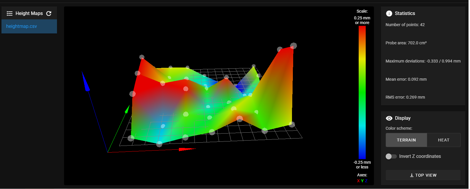
Can you post a photo of your heightmap image with the deviations, etc?
Can you also post the gcode file you're executing? How fast are the moves?You may be able to use M376 to set a taper off height for the compensation, so that the slower first layers are compensated to allow for good first layer and then slowly over a few mm it tapers off.
https://duet3d.dozuki.com/Wiki/Gcode?revisionid=HEAD#Section_M376_Set_bed_compensation_taper
-
@phaedrux after looking at the height map from my first few attempts, I have given my heat bed a clean and repeated the test it now moves without jerking but the bed ain't flat by far!
the gcode I test with is
G28 XY
G0 X100 Y100 F10000
G3 X100 Y100 I25
G3 X100 Y100 I25
G0 X10 Y10
G0 X100 Y100 F10000
G2 X100 Y100 I25
G2 X100 Y100 I25
G0 X10 Y10
(repeated over and over)this is essentially a series of circles both clockwise and anti-clockwise @ 168mm/s, I will take a look at M376 along with a further clean of my bed hopefully it will help get me back printing until I can figure out better flatter build surface that I can print on that doesn't cost the earth to replace from time to time!
-
I think we see now the reason for the halting motion. I suspect that your bed surface isn't ideal for the IR probe, and so those large spikes are actually just spurious from a bad IR detection. Those spikes then require the Z axis to lurch up and down rapidly during the fast moves. The slow Z jerk/accel force it to slow down in XY as well.
Try placing a piece of plain paper over your bed surface and re-probing the mesh to see if it becomes flatter.
-
@phaedrux, After multiple attempts with both black and white paper including a comical poor chase the hot end around with the paper, I resorted to using just the bare unpolished aluminium bed, pretty much proof the glass bed is causing the sensor a head ache the two blue areas are chamfered screw holes I believe.
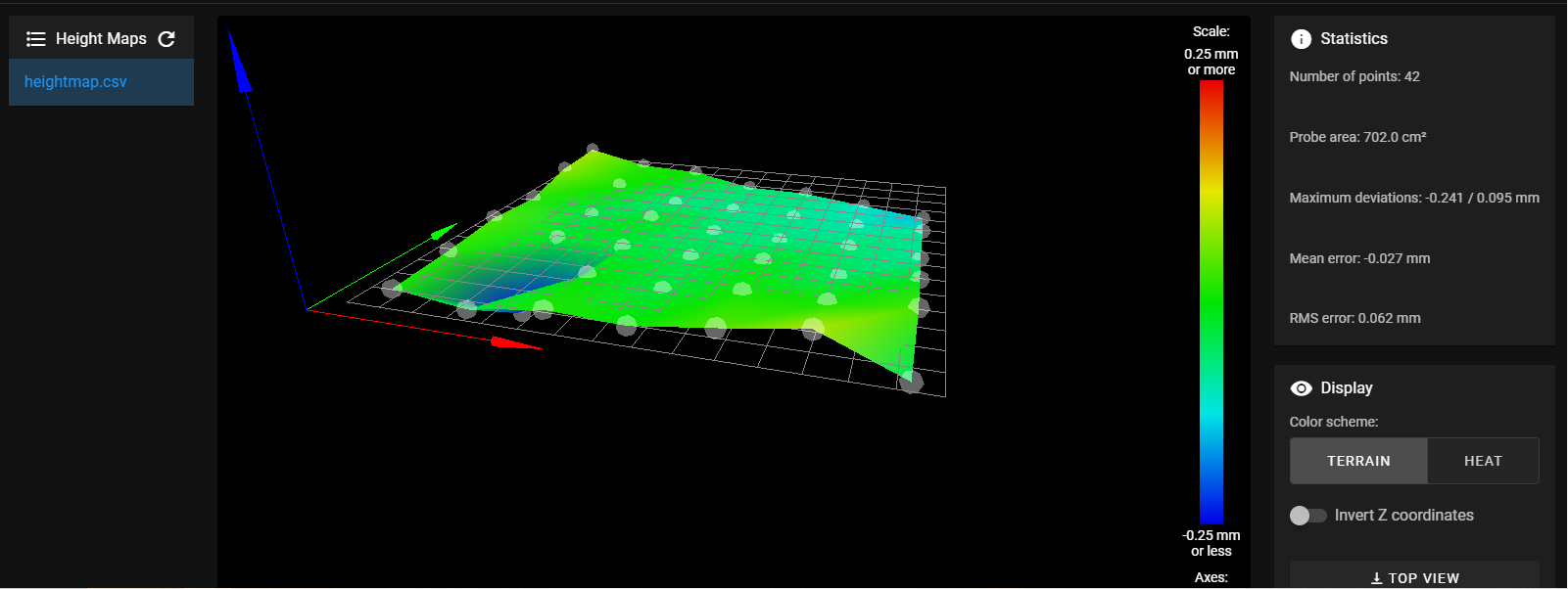
I have ordered some Lokbuild to replace the kapton tape.
Thankyou all for your help and for educating me