Accelerometer data interpretation
-
@silviuz said in Accelerometer data interpretation:
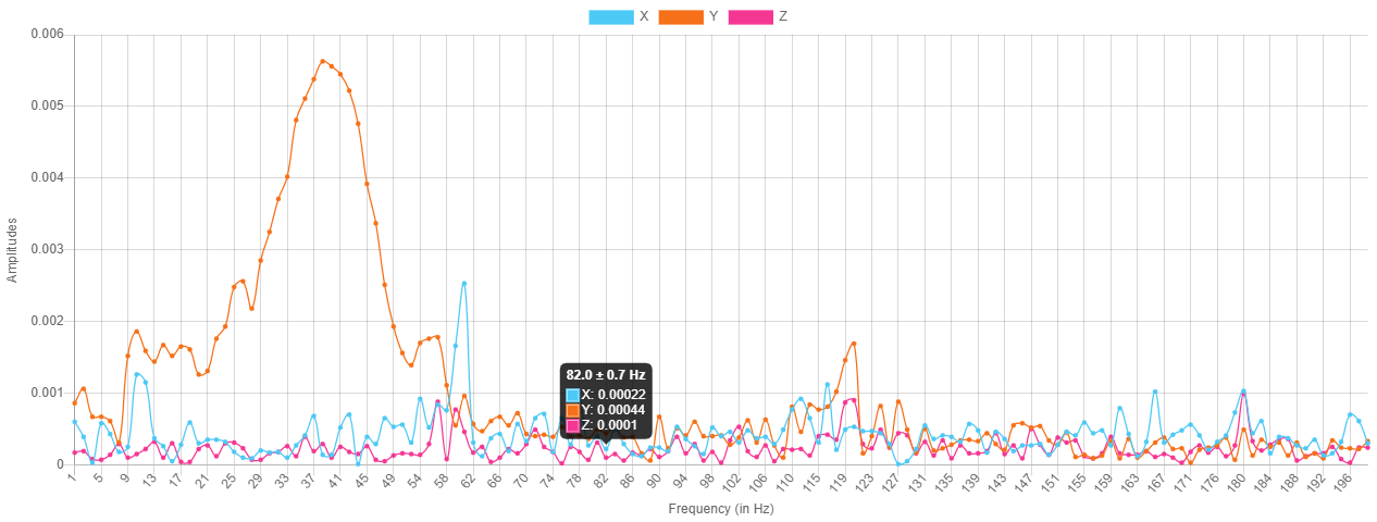
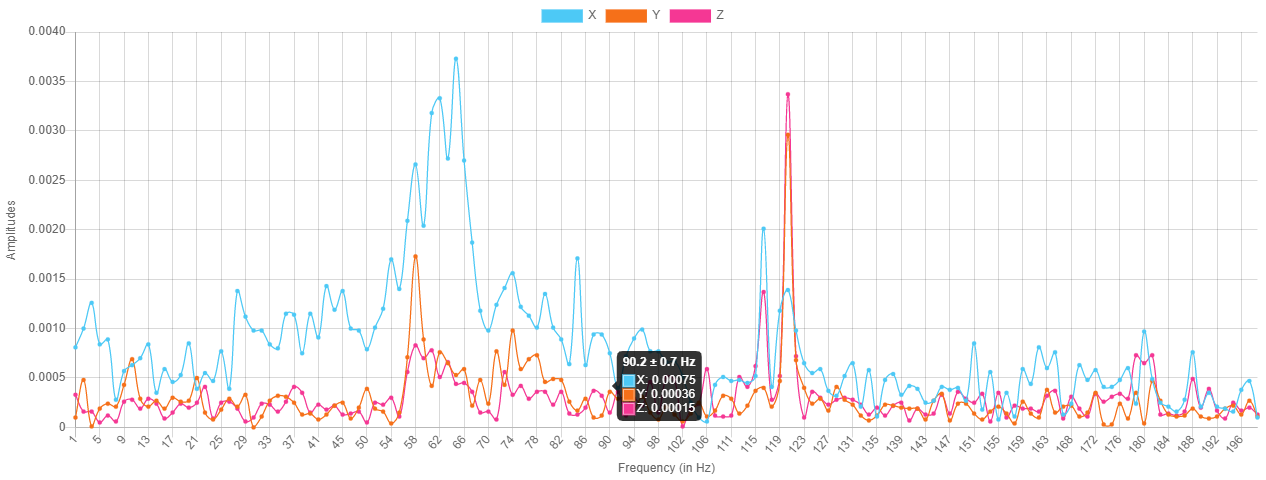
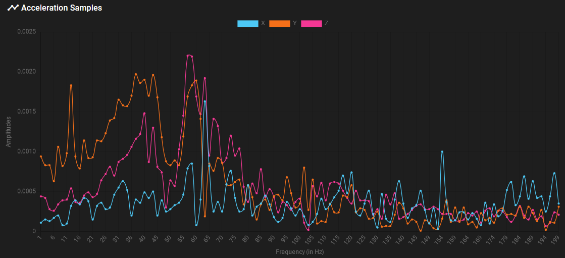
Not exactly scientific, but check out the magnitudes of the X and Y vibrations. Typically the recommendation is to select an input shaping frequency that is the lowest of the frequencies of interest. For both you Y and X tests, you have X-axis peaks around 61Hz, at amplitudes between .0025-.0035. Y-axis peaks at ~.0055, which is higher than the X peaks, and occurs at ~41Hz. My thoughts are that if you select ~41Hz as your input shaping frequency, you'll target the worst frequency of the entire system.
Also, super cool on converting a Stratasys FDM 2000 over to the Duet ecosystem.
-
@sebkritikel
Thank you! I will try to implement your recommendations
 image url)
-
@silviuz you can also choose EI3 input shaping centred on a frequency between the X and Y ringing frequencies, which should be fairly effective at suppressing both.
Duet WiFi hardware designer and firmware engineer
Please do not ask me for Duet support via PM or email, use the forum
http://www.escher3d.com, https://miscsolutions.wordpress.com -
@dc42 Thank you for your reply.
I've tried 41HZ without a significant success.
After a couple of ringhing towers I found that indeed "ei3" it's doing the best cancellation at 28HZ.
I hope that in the future if it's possible..... to have implemented a automatic axis tuning similar like the Teknic Clearpath.
Thank you again for your help. -
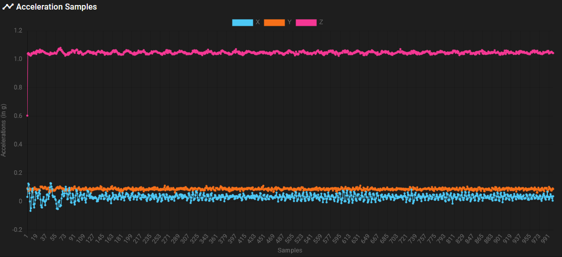
@dc42 Sorry for the delay. I figured out that despite the chip is marked differently than the image on the datasheet, the axed are oriented in the same way. To test it i did statical reading while holding the accelerometers in different position and checking if the expected axes reported nearly 1g.
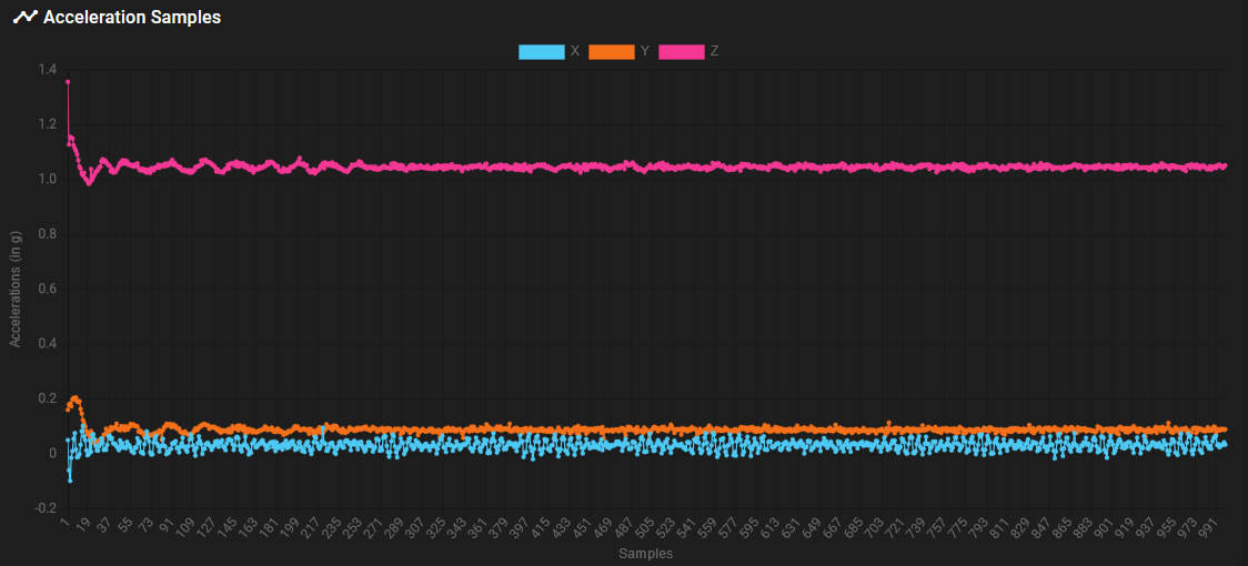
Now that i have figured that out, here's the results of the previous macros before and after FFT:
X AXIS:
Y AXIS:
Edit:
There's seems to be something wrong when selecting axes to be acquired with M956.
If i don't specify axes, i get all the readings (but i don't know if they are in the correct order).
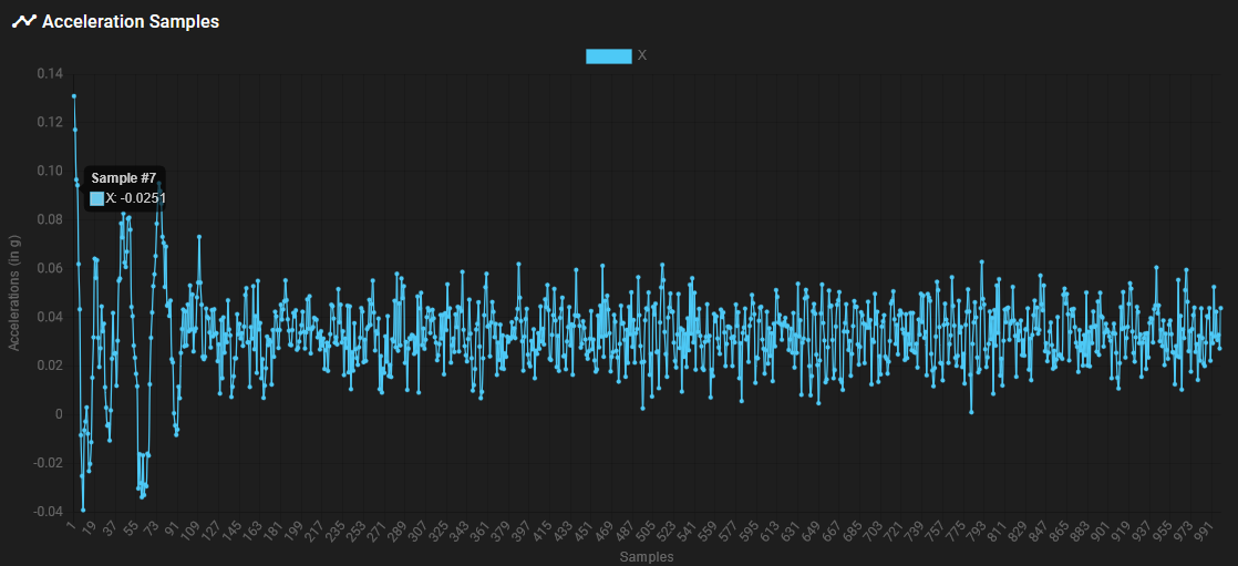
If i specify X then i get readings
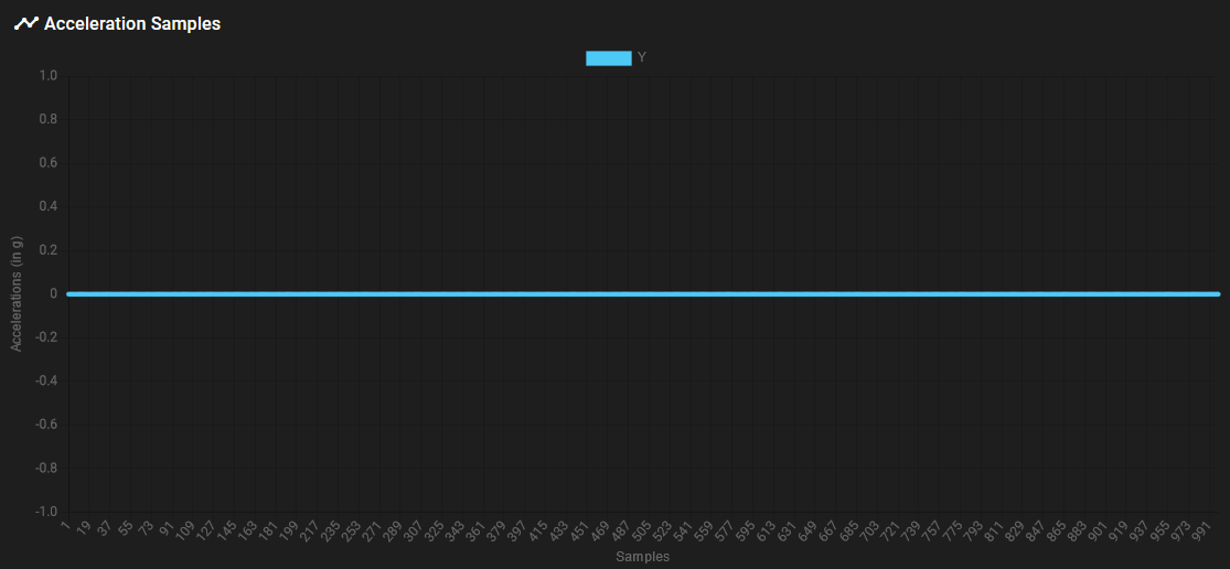
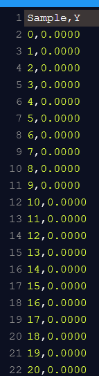
I i specify Y i get all 0 values
I i specify XY i get same values for X as only X and all 0 values for Y
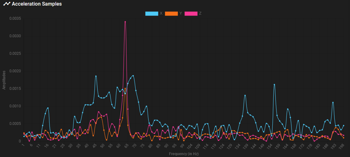
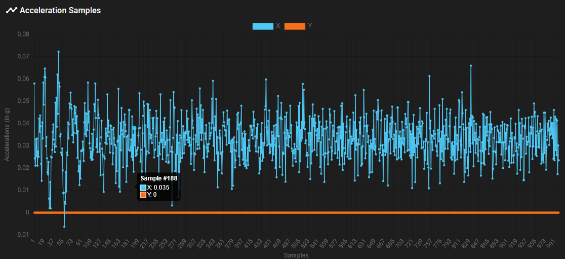
I i specify XYZ i get same results as nothing specified.Here's some graph:
ONLY X
ONLY Y
X AND Y
Code (changed axes just after M956)
M593 P"none" G1 Y-50 G4 S2 G4 P10 G1 Y100 F20000 M400 M956 X P0 S1000 A0 F"test.csv" -
@mikes said in Accelerometer data interpretation:
There's seems to be something wrong when selecting axes to be acquired with M956.
If i don't specify axes, i get all the readings (but i don't know if they are in the correct order).
If i specify X then i get readings
I i specify Y i get all 0 values
I i specify XY i get same values for X as only X and all 0 values for Y
I i specify XYZ i get same results as nothing specified.Thanks, I'll check it. It could be that incorrect values are stored in the .csv files, or the plugin is interpreting them the wrong way. Can you open the .csv files in the System tab of DWC and see if the data and column headings look OK?
Duet WiFi hardware designer and firmware engineer
Please do not ask me for Duet support via PM or email, use the forum
http://www.escher3d.com, https://miscsolutions.wordpress.com -
@dc42 csv is displayed correctly as csv contains 0 for each row in Y axis.
-
@mikes thanks, the problem is in RRF then.
-
@mikes this issue is now fixed in the source code. The fix will be included in the next beta.
Duet WiFi hardware designer and firmware engineer
Please do not ask me for Duet support via PM or email, use the forum
http://www.escher3d.com, https://miscsolutions.wordpress.com -
@dc42 thank you David. Any chance to get a compiled binaries for Duet2wifi to test it out? Still have to test input shaping because i was not sure if the data was reliable... i saw resonance on Z axis for example while testing X or Y axis.
-
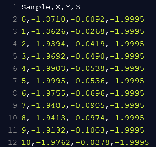
@dc42 just had 2 hours to play with a VM and managed to compile the source.
On the current source i can read correct data from X and Y axes (both together or alone) but Z axis is always reading -1.9995 as value. Also X Values is near -2 and it seems not correct to me. Shouldn't X and Y be near 0 and Z to -1 with a reading without moves?
UPDATE:
So i've looked at the changes you made in the latest version and came up with this fix:
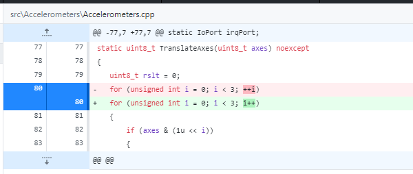
I am not a programmer, but i've tested it and it seems that it has fixed it. Can you confirm?Maybe it's only another error that fixes my particular issue
Nevermind all! I've looked more at C++ language and understood that in the for loop ++i has the same behaviour of i++ so that was not the fix. However now it seems to be working fine. I'll do more tests but it seems that there was something wrong with the accelerometers itself, returning wrong data...
-
@mikes said in Accelerometer data interpretation:
@dc42 thank you David. Any chance to get a compiled binaries for Duet2wifi to test it out? Still have to test input shaping because i was not sure if the data was reliable... i saw resonance on Z axis for example while testing X or Y axis.
The workaround is to always select all axes, which is the default.