Mesh compensation results backwards
-
config.g
; Configuration file for Duet WiFi (firmware version 3.0)
; executed by the firmware on start-up
;
; MODEL Railcore-II 400 TC

; General preferences
G90                                       ; Send absolute coordinates...
M83                                       ; ...but relative extruder moves

;;;;;;;;;;;;;;;;;;;
;;;   Network   ;;;
;;;;;;;;;;;;;;;;;;;
M550 P""                    ; Set machine name
M552 S1                                   ; Enable network
M586 P0 S1                                ; Enable HTTP
M586 P1 S0                                ; Disable FTP
M586 P2 S0                                ; Disable Telnet

;;;;;;;;;;;;;;;;;;
;;;   Drives   ;;;
;;;;;;;;;;;;;;;;;;
M584 Z2:5 C8 E3:4                           ; two Z motors connected to driver 2 & 5, Tool Coupler C is Driver 9, Extruder 0 driver 3, Extruder 1 driver 4
M667 S1 								  ; switch to CoreXY mode
M669 K1                                   ; Set kinematics type to CoreXY
M569 P0 S0                                ; Drive 0 goes backwards (X)
M569 P1 S0                                ; Drive 1 goes backwards (Y)
M569 P2 S1                                ; Drive 2 goes forwards
M569 P3 S0                                ; Drive 3 Tool 0 goes forwards OMC Pancake Direct Drive
M569 P4 S1                                ; Drive 4 Tool 1 goes forwards LD0 LDO-36STH20-0504AHG
M569 P8 S0								  ; Drive 9 Tool Changer

M906 X900.00 Y900.00 Z800.00 C400 E600:500 I30    ; Set motor currents (mA) and motor idle factor in per cent

M350 X16 Y16 Z16 E16:16 I1                ; Configure microstepping with interpolation
M350 C8 I0                                ; Configure C microstepping with interpolation (Tool Changer)

M92 X201.2499 Y201.2499 Z1601.584008 C100 E421.1332199:690    ; Set steps per mm (BMG Extruder), T8x2 1-Start Lead Screw

;; This section sets the maximums of the axis movements.
;;  I have been told it does not make sense to set these too low as the actual
;;  requested speeds will be set by the G-Code and likely tuned in the slicer.
M201 X2000.00 Y2000.00 Z60.00 C500 E600:600  ; Set accelerations (mm/s^2) https://wilriker.github.io/maximum-acceleration-calculator/
M203 X16000.00 Y16000.00 Z720.00 C5000 E4800:3600   ; Set maximum speeds (mm/min) / Bondtech starts to skip at 1000 so back off to 80%.
M566 X900.00 Y900.00 Z12.00 C2 E1600:300   ; Set maximum instantaneous speed changes (mm/min)
;Let slicer set...;M204 P1000 T3000	  	  ; Set printing and travel accelerations
;M592 D1 A-0.046992623 B0.010089628 C0.045893262	; Non-Linear Extrusion Advance

;M671 - Define positions of Z leadscrews or bed levelling screws (not to be confused with screws in the bed).
M671 X-80:480 Y200:200 S5                 ; leadscrews at left and right of X axis and allow 5mm of correction between screws.
M84 S30                                   ; Set idle timeout

; Axis Limits
M208 X0 Y0 Z0.05 C0 S1                    ; Set axis minima X-Axis will not lower than 0.05mm to bed.
M208 X420 Y410 Z400 C240 S0               ; Set axis maxima

; AAR
M593 F50                                  ; cancel ringing at 50Hz (https://forum.e3d-online.com/threads/accelerometer-and-resonance-measurements-of-the-motion-system.3445/)

M575 P1 B115200 S1						  ; PanelDue communications

;;;;;;;;;;;;;;;;;;;
;;;   SENSORS   ;;;
;;;;;;;;;;;;;;;;;;;
;; (BED) Sensor0 -> H0
M308 S0 P"bed_temp" Y"thermistor" R4700 T100000 B3950	; bed temperature sensor

;; (BED SSR) Sensor
M308 S9 P"duex.e6temp" A"BED-SSR" Y"thermistor" R4700 T100000 B3950	; BED SSR temperature sensor

;; (Tool 0) Sensor1 -> H1
M308 S1 P"spi.cs2" Y"rtd-max31865"  	  ; create sensor number 1 as a PT100 sensor in the second position on the Duet 2 daughter board connector
M308 S2 P"spi.cs1" Y"rtd-max31865"  	  ; create sensor number 2 as a PT100 sensor in the second position on the Duet 2 daughter board connector


;;;;;;;;;;;;;;;;;;;
;;;   Heaters   ;;;
;;;;;;;;;;;;;;;;;;;
;; Bed
M950 H0 C"bed_heat" Q100 T0 			; heater 0 uses the PIN bed_heat, PWM frequency 100Hz, Temperature sensor 0
M143 H0 S120                              	; Set temperature limit for heater 0 to 120C even though it can go much higher.
;M307 H0 A192.7 C889.9 D2.0 S1.00 V24.3 B0 	; Disable bang-bang mode for the bed heater and set PWM limit Keenovo 1000W
M140 H0

;; Heater 1 (Tool 0)
M950 H1 C"e0_heat" T1                	; heater 1 uses the PIN e0_heat and Temperature sensor 1
M143 H1 S340                            ; Set temperature limit for heater 1 to 300C
;M307 H1 A469.1 C236.9 D4.8 S1.00 V24.1 B0

;; Heater 2
;M950 H2 C"nil" ; disable heater 2 and free up the associated pin
M950 H2 C"e1_heat" T2                	; heater 1 uses the PIN e0_heat and Temperature sensor 1
M143 H2 S340                            ; Set temperature limit for heater 1 to 300C

;; Heater 3
M950 H3 C"nil" ; disable heater 2 and free up the associated pin

;; Heater 4
M950 H4 C"nil" ; disable heater 2 and free up the associated pin

;; Heater 5
M950 H5 C"nil" ; disable heater 2 and free up the associated pin

;; Heater 6
M950 H6 C"nil" ; disable heater 2 and free up the associated pin

;; Heater 7 (Used for BLTouch)
M950 H7 C"nil" ; disable heater 2 and free up the associated pin


;;;;;;;;;;;;;;;;
;;;   Fans   ;;;
;;;;;;;;;;;;;;;;
; (Tool 0)
;; (E3D v6) (Stock Fan)
M950 F10 C"fan0" Q167					; Create Fan 10, PWM Frequency 167Hz
M106 P10 H1 T40							; Turn on thermostatic control above 40°C.
;; T0 Part Cooling
M950 F1 C"fan1"  						; Create Fan 1, PWM Frequency 500Hz
M106 P1 S0 H-1							; Set Fan 1 to on (100%) and Thermostatic control off.

; (Tool 1)
;; (E3D v6) (Stock Fan)
M950 F11 C"fan2" Q167					; Create Fan 11, PWM Frequency 167Hz
M106 P11 H2 T40							; Turn on thermostatic control above 40°C.
;; T1 Part Cooling
M950 F2 C"duex.fan3"  					; Create Fan 2, PWM Frequency 500Hz
M106 P2 S0 H-1							; Set Fan 2 to on (100%) and Thermostatic control off.


;;;;;;;;;;;;;;;;;
;;;   Tools   ;;;
;;;;;;;;;;;;;;;;;
;; Tool 0 - Extruder 0 - E3D v6
M563 P0 D0 H1 F0 S"Tool-0"            ; Define tool 0 -> Heater 1 -> Fan 0
G10 P0 X0 Y0 Z-1.55                       ; Set tool 0 axis offsets (-1.77)
G10 P0 R0 S0                       		  ; Set initial tool 0 active and standby temperatures to 0C

;; Tool 1 - Extruder 1 - E3D v6
M563 P1 D1 H2 F2 S"Tool-1"            ; Define tool 0 -> Heater 1 -> Fan 0
;G10 P1 X-0.23 Y0.1 Z-1.82                 ; Set tool 0 axis offsets (-1.67)
G10 P1 X0.15 Y0.0 Z-1.82                 ; Set tool 0 axis offsets (-1.67)
G10 P1 R0 S0                       		  ; Set initial tool 0 active and standby temperatures to 0C


;;;;;;;;;;;;;;;;;;;;
;;;   Endstops   ;;;
;;;;;;;;;;;;;;;;;;;;
M574 X1 S1 P"!x_stop" 				; Set active high endstops
M574 Y1 S1 P"!y_stop" 				; Set active low endstops
M574 Z1 S2							; configure Z-probe endstop for low end on Z


; Filament Sensor
; Placed in Tool Configs...
;M591 D0 P3 c"e0_stop" S1 R40:190 L25.5 E3.0	; Duet3D rotating magnet sensor extruder drive 0 is connected to E0, enabled, sensitivity 24.8mm.rev, 70% to 130% tolerance, 3mm detection length
;M581 P"e0_stop" T1 S1 R1 				; Filament run-out sensor triggers a pause
;M581 P"e1_stop" T2 S1 R1 				; Filament run-out sensor triggers a pause


; Z-Probe
;; BLTouch Sensor
;  Z# = Trigger height. 1.5mm is normal for BlTouch, Relative to Tool 0 height to bed.
;  P# = Trigger value. 25-100. Lower it if nothing happens.
;  XY# = Placement of probe relative to your nozzle. Called offset. In mm.
M558 P9 C"^z_probe.in" K0 H5 Z1 F360 T10000 A10 S0.005	; BLTouch connected to Z probe IN pin
M950 S0 C"duex.pwm5"                ; create servo pin 0 for BLTouch

;; Sensor to right (negative X) of hotend
G31 P25 K0 X31.75 Y-34.4 Z0.90		; Z probe trigger value, offset in relation to nozzle. Larger trigger brings hotend closer to bed.
;G31 P25 K0 X77.75 Y-45.4 Z1.00		; Z probe trigger value, offset in relation to nozzle. Larger trigger brings hotend closer to bed.
M557 X10:370 Y20:370 S20			; Define mesh grid Offset X to account for Z-Trigger.

; Tool Changer
M574 C1 S3                          ; Stall detect coupler at low end of its range
;; Stall Detection
M915 C S3 F1 H400 R1                ; Coupler
M915 X S5 F1 H400 R2
M915 Y S4 F1 H400 R2


; Automatic saving after power loss is not enabled
M911 S10 R11 P"M913 X0 Y0 G91 M83 G1 Z3 E-2 F1000" ; Set voltage thresholds and actions to run on power loss

; Custom settings are not configured
M501

M98 P"/sys/custom_global_vars.g"
homex.g
; homex.g
; called to home the X axis
;
G91               ; relative positioning
G1 Z5 F6000 H2    ; lift Z relative to current position
G1 X-430 F6000 H1 ; move quickly to X axis endstop and stop there (first pass)
G1 X5 F6000       ; go back a few mm
G1 X-430 F360 H1  ; move slowly to X axis endstop once more (second pass)
G1 Z-5 F6000 H2   ; lower Z again
G1 F6000          ; Set movement speed
G90               ; absolute positioning
homey.g
; homey.g
; called to home the Y axis
;
G91               ; relative positioning
G1 Z5 F6000 H2    ; lift Z relative to current position
G1 H1 Y-405 F6000 ; move quickly to Y axis endstop and stop there (first pass)
G1 Y5 F8000       ; go back a few mm
G1 H1 Y-405 F360  ; move slowly to Y axis endstop once more (second pass)
G1 Z-5 F6000 H2   ; lower Z again
G1 F6000		  ; Set movement speed
G90               ; absolute positioning
homez.g
; homez.g
; called to home the Z axis
;
G91              ; relative positioning
G1 Z5 F6000 H2   ; lift Z relative to current position
G90              ; absolute positioning

; Z-Axis probe likely triggers beyond tool height.
; If we have an active tool we need to drop it now.
if state.currentTool >= 0
  M28 "/sys/tprevious.g"
  T{state.currentTool}
  M29
M98 P"/sys/tactive.g" > null
; Delete the register file so we don't try to dock again.
M30 "/sys/tactive.g"

G1 X190 Y220 F6000 ; go to first probe point
G30              ; home Z by probing the bed

;; Points are not related to bed coordinates, but rather probe coordinates.
;; 2 Point
G30 P0 X35 Y190 Z-9999        ; Left Center
G30 P1 X371 Y190 Z-9999 S2    ; Right Center

; Load previous tool
M98 P"/sys/tprevious.g"
M30 "/sys/tprevious.g"

; Load Height Map
M375
homec.g
; homec.g
; called to home the C axis (coupler)
;
; Needed configuration:
;  M574 C1 S3        ; Endstop config: C1 = low end, S3 = Single motor load detection for coupler
;  M350 C8 I0        ; Configure 8x microstepping, no interpolation
;  M208 C0:240 S0    ; Set axis minima and maxima.
;  M906 ... C400     ; Set coupler motor current to 400 [mA] (stock config)
;  M92  ... C100     ; Set coupler steps per mm to 100 [steps/mm]
;  M566 ... C2       ; Set coupler jerk to 2 (stock config)
;  M203 ... C5000    ; Set maximum speeds [mm/min] (stock config)
;  M201 ... C500     ; Set accelerations [mm/s^2] (stock config)
;  M915 C S3 F1 H400 ; Coupler Stall Detection
;
;  Comment on M915: I had a problem that sensitivity S3 always stopped and sensitivity S4 did detect nothing using F0.
;                   This worked using F1.
;
; Macro Coordinates: Lock position is C40, unlock position is C123

; The coupler doesnt reliably stall, so this code drives it to the end stop reliably with as little current as possible
; First we give the system a "kick" at full power
M913 C100			; Set C motor 100% current
M400				; Wait for moves to finish
G1 H2 C-5 F5000		; kick it!!

; Now home
M400
G91                 ; Relative coordinates
M913 C85            ; Crash fallback: Set C motor to lower current, but <= 80 was unstable low.
G1 H1 C10 F5000     ; Space min end or stall at max end, needed for acceleration towards near min end.
G1 H1 C-1000 F5000  ; Try to stall at min end, reset to min-axis M203 = 0 coordinate

M400
G92 C0              ; Crash fallback: coordinates reset to 0 in case stall did not reset to min-axis M203 coordinate
G90                 ; Back to absolute coordinates
M913 C100           ; Set C motor 100% current

;Open Coupler
; in most cases the homing will find 0, but not move back (for whatever reason)
; if we lock the coupler first this moves past the unlock more times than not.
; find that unlocking afterwards works...  Go figure.
M98 P"/macros/Tools/Tool-Lock"
M98 P"/macros/Tools/Tool-Unlock"
homeall.g
; homeall.g
; called to home all axes
;
G91                     ; relative positioning
G1 Z5 F6000 H2          ; lift Z relative to current position

; Tool changer we want to home Y first to pull away from tools.
; Home Y
M98 P"homey.g"

; Home X
M98 P"homex.g"

; Home Z
M98 P"homez.g"

; Home C (Tool Coupler)
M98 P"homec.g"


G90               ; absolute positioning
G1 X200 Y200 F6000	; Move to center of bed.

;Load height map from file
G29 S1
meshcompensation (macro)
M140 H0 S70 M190 S70 ; Home the Z-Axis M98 P"homeall.g" ; Clear the current height map. G29 S2 ; Define probing grid M557 X10:370 Y20:320 S20 ; Perform Mesh Compensation probing. G29 ; Turn off bed. M140 S0 -
My system homes with 0,0 in closest to the left when looking at the front. No issues printing, but getting that first layer has been an issue when moving to high in the X-Axis (maybe Y-Axis too).
Y-trigger is on the far right at the closest to me from the front of the machine
X-trigger is on the X-Axis (carriage), left side looking at the machine. It will trigger when the head moves far enough to the left to hit the side rail holder. -
Can you post a photo of your displayed heightmap?
Your config looks ok for your description of the endstop placement etc.
-
@phaedrux
I need to redo it as I have it all reversed now and didn't save the previous, but you can see here the X & Y are reversed from what I got from the original mesh compensation. I ran it twice with about the same results.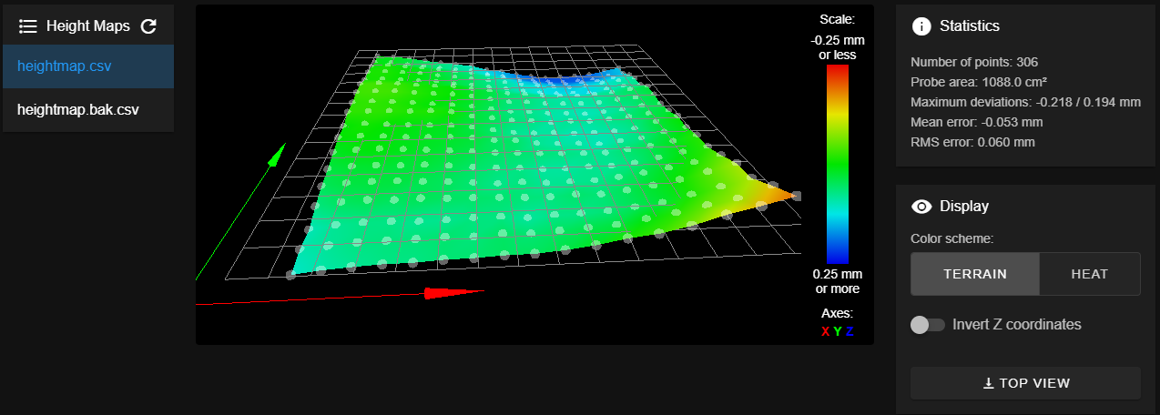
heightmap.csv
RepRapFirmware height map file v2 generated at 2021-08-20 12:08, min error -0.249, max error 0.161, mean -0.028, deviation 0.067 axis0,axis1,min0,max0,min1,max1,radius,spacing0,spacing1,num0,num1 X,Y,10.00,370.00,20.00,320.00,-1.00,20.00,20.00,19,18 0,0,-0.109,-0.091,-0.08,-0.072,-0.071,-0.062,-0.06,-0.052,-0.051,-0.038,-0.018,0.012,0.03,0.065,0.115,0.152,0.194 0,0,-0.095,-0.082,-0.07,-0.067,-0.065,-0.06,-0.066,-0.054,-0.062,-0.052,-0.042,-0.034,-0.007,0.02,0.055,0.084,0.147 0,0,-0.099,-0.08,-0.072,-0.072,-0.078,-0.077,-0.069,-0.07,-0.085,-0.073,-0.071,-0.063,-0.047,-0.027,0.014,0.051,0.095 0,0,-0.069,-0.051,-0.044,-0.051,-0.046,-0.053,-0.056,-0.06,-0.065,-0.068,-0.058,-0.064,-0.046,-0.023,0.005,0.045,0.089 0,0,-0.048,-0.036,-0.033,-0.034,-0.044,-0.05,-0.061,-0.074,-0.069,-0.08,-0.078,-0.076,-0.061,-0.04,-0.015,0.012,0.053 0,0,-0.035,-0.026,-0.024,-0.031,-0.031,-0.042,-0.055,-0.065,-0.071,-0.085,-0.086,-0.078,-0.079,-0.065,-0.037,-0.007,0.023 0,0,-0.018,-0.007,-0.004,-0.013,-0.021,-0.03,-0.039,-0.053,-0.06,-0.065,-0.07,-0.076,-0.077,-0.061,-0.042,-0.016,0.019 0,0,-0.001,0.003,-0.004,-0.013,-0.017,-0.022,-0.03,-0.051,-0.056,-0.079,-0.088,-0.09,-0.099,-0.082,-0.068,-0.031,-0.003 0,0,-0.001,0.01,0.001,-0.007,-0.013,-0.018,-0.035,-0.056,-0.078,-0.086,-0.086,-0.097,-0.095,-0.09,-0.073,-0.033,0.002 0,0,0.024,0.025,0.023,0.016,0.016,0.006,-0.029,-0.044,-0.064,-0.071,-0.088,-0.08,-0.086,-0.074,-0.063,-0.043,-0.026 0,0,0.023,0.026,0.02,0.01,-0.003,-0.013,-0.027,-0.047,-0.069,-0.075,-0.089,-0.094,-0.101,-0.092,-0.078,-0.054,-0.04 0,0,0.033,0.036,0.034,0.02,0.009,0.002,-0.017,-0.04,-0.064,-0.068,-0.081,-0.086,-0.089,-0.085,-0.066,-0.056,-0.034 0,0,0.035,0.036,0.029,0.014,0.005,0.001,-0.023,-0.036,-0.061,-0.068,-0.081,-0.09,-0.093,-0.083,-0.074,-0.053,-0.033 0,0,0.01,0.012,0.003,-0.009,-0.017,-0.036,-0.05,-0.067,-0.084,-0.103,-0.12,-0.129,-0.128,-0.133,-0.105,-0.084,-0.074 0,0,0.013,0.014,0.004,-0.006,-0.025,-0.039,-0.053,-0.073,-0.089,-0.11,-0.119,-0.132,-0.142,-0.131,-0.111,-0.097,-0.081 0,0,0.005,0.011,-0.004,-0.015,-0.031,-0.051,-0.065,-0.085,-0.108,-0.135,-0.15,-0.163,-0.171,-0.159,-0.15,-0.13,-0.103 0,0,-0.009,-0.016,-0.035,-0.05,-0.066,-0.081,-0.092,-0.125,-0.144,-0.171,-0.187,-0.2,-0.204,-0.199,-0.191,-0.162,-0.144 0,0,-0.006,-0.017,-0.03,-0.053,-0.07,-0.087,-0.102,-0.136,-0.154,-0.181,-0.199,-0.218,-0.212,-0.207,-0.198,-0.17,-0.144 -
First off you should update to firmware version 3.3.
Why are you using M98 to invoke things like homex.g?
There are commands to do that.
For example:
- G28 X will invoke homex.g
- G28 Y will invoke homey.g
- G28 Z will invoke homez.g
- G28 will invoke homeall.g
-
I am running v3.3, eagerly awaiting a stable 3.4 with the accelerometer.
")
I don't recall why I used M98, but I think it was due to an issue with calling G28 a few versions ago and never changed it back. -
@phaedrux
After validating my tool heights and re-running my meshcompensation macro here is the output: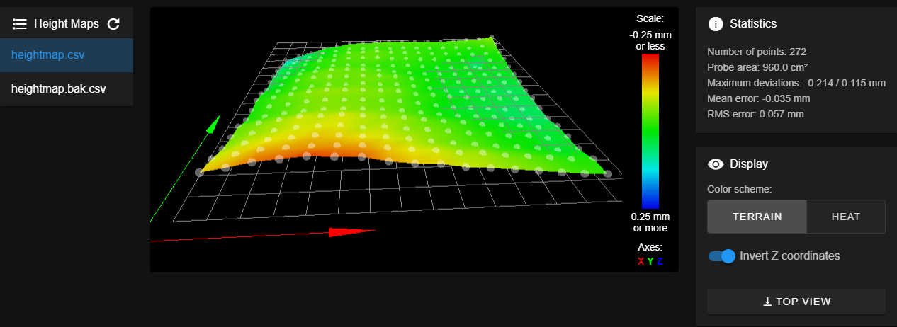
heightmap.csv
RepRapFirmware height map file v2 generated at 2021-08-20 14:48, min error -0.214, max error 0.115, mean -0.035, deviation 0.057
axis0,axis1,min0,max0,min1,max1,radius,spacing0,spacing1,num0,num1
X,Y,10.00,370.00,20.00,320.00,-1.00,20.00,20.00,19,16
      0,      0, -0.141, -0.163, -0.191, -0.203, -0.214, -0.205, -0.197, -0.164, -0.144, -0.135, -0.108, -0.096, -0.080, -0.064, -0.046, -0.031, -0.023
      0,      0, -0.114, -0.137, -0.159, -0.165, -0.169, -0.168, -0.163, -0.143, -0.124, -0.113, -0.092, -0.085, -0.062, -0.050, -0.035, -0.018, -0.016
      0,      0, -0.079, -0.109, -0.126, -0.133, -0.145, -0.139, -0.128, -0.117, -0.100, -0.077, -0.058, -0.045, -0.025, -0.013,  0.002,  0.021,  0.015
      0,      0, -0.062, -0.083, -0.097, -0.114, -0.118, -0.119, -0.098, -0.101, -0.078, -0.068, -0.052, -0.032, -0.019,  0.000,  0.003,  0.029,  0.018
      0,      0, -0.052, -0.068, -0.086, -0.109, -0.105, -0.114, -0.099, -0.085, -0.076, -0.055, -0.038, -0.025, -0.003,  0.006,  0.018,  0.032,  0.023
      0,      0, -0.012, -0.034, -0.053, -0.066, -0.076, -0.075, -0.069, -0.061, -0.049, -0.027, -0.008,  0.009,  0.017,  0.025,  0.045,  0.050,  0.049
      0,      0, -0.009, -0.035, -0.046, -0.064, -0.072, -0.067, -0.066, -0.054, -0.046, -0.026, -0.002,  0.017,  0.028,  0.036,  0.049,  0.051,  0.045
      0,      0, -0.015, -0.031, -0.054, -0.073, -0.081, -0.077, -0.072, -0.065, -0.056, -0.027, -0.016,  0.002,  0.013,  0.027,  0.029,  0.037,  0.036
      0,      0,  0.003, -0.013, -0.032, -0.044, -0.057, -0.053, -0.061, -0.047, -0.042, -0.024, -0.002,  0.023,  0.037,  0.035,  0.043,  0.049,  0.040
      0,      0,  0.038,  0.003, -0.036, -0.058, -0.062, -0.058, -0.062, -0.059, -0.049, -0.025, -0.008,  0.006,  0.015,  0.008,  0.024,  0.030,  0.025
      0,      0,  0.034,  0.003, -0.029, -0.046, -0.059, -0.058, -0.055, -0.042, -0.025, -0.012,  0.001,  0.004,  0.009,  0.009,  0.019,  0.024,  0.017
      0,      0,  0.047,  0.023,  0.002, -0.019, -0.035, -0.038, -0.034, -0.025, -0.022, -0.023, -0.009,  0.005,  0.010,  0.011,  0.020,  0.018,  0.010
      0,      0,  0.055,  0.030,  0.004, -0.028, -0.030, -0.045, -0.050, -0.049, -0.034, -0.032, -0.021, -0.018, -0.004, -0.001,  0.069,  0.001, -0.011
      0,      0,  0.075,  0.045,  0.017, -0.003, -0.022, -0.047, -0.048, -0.054, -0.041, -0.035, -0.031, -0.018, -0.016, -0.008, -0.003, -0.010, -0.019
      0,      0,  0.103,  0.072,  0.042,  0.007, -0.014, -0.031, -0.031, -0.036, -0.026, -0.031, -0.026, -0.020, -0.021, -0.022, -0.014, -0.029, -0.045
      0,      0,  0.115,  0.078,  0.044,  0.004, -0.012, -0.036, -0.041, -0.043, -0.051, -0.044, -0.046, -0.044, -0.039, -0.043, -0.051, -0.056, -0.079
So when I go to print and something is near the 0 side of the X-Axis it gets nice and smooshed against the bed, but moving to the high side of the X-Axis and there is too much gap and I'm losing adhesion. This pattern seems to persist up and down the Y-Axis of the high-side of the X-Axis. This is what leads me to believe my resulting heightmap is coming out backward. When I flipped things around I was getting things to stick, but a bit more than it should.
It seems odd to me that the center area that I home on isn't closer to 0.
Maybe next I'll try turning off mesh compensation and doing a manual check of each corner.
-
@gamefanatic3d said in Mesh compensation results backwards:
I am running v3.3, eagerly awaiting a stable 3.4 with the accelerometer.
Your config.g file lists firmware 3.0 - that threw me off.
With 3.3 the G29 command will invoke the file mesh.g if it exists, which is intended to be used to create the height map needed for mesh compensation.
And the G32 command invokes bed.g which is intended to be used to level the bed using multiple G30 commands.
Since the DWC has both G32 and G29 in it's compensation and calibration pull-down menu, if you want these to work you may want to make use of mesh.g and bed.g.
I don't recall why I used M98, but I think it was due to an issue with calling G28 a few versions ago and never changed it back.
There are some side effects of calling G28 that you don't get when using M98.
One such side effect is marking the axis as un-homed prior to invoking the associated file.
What else it might do I don't know.
But given the importance of actually knowing each axis is homed I suggest you return to using G28.
And you can simply the use of M98 a bit, if desired. M98 P"/sys/some_file.g" is the same as M98 P"some.file.g". When you don't specify a folder it defaults to the system folder, sys.
Frederick
-
There are times when it is important to set the Z=0 datum using a single G30.
This must be done:
- after leveling the bed with G30 commands as you do in your homez.g file
- before creating the height map
- before loading the height map
Whatever XY point you use you must use the same point whenever you set the Z=0 datum.
In your homez.g file you level the bed with a pair of G30 commands and shortly thereafter load the height map using M375 without first setting the Z=0 datum which may have changed as a result of the bed leveling.
-
Based on your feedback I added an additional G30 just after my Z-Axis leveling and before loading the heightmap. Also changed the points at which I am measuring for the left and right to exactly align with the point I am looking for the G30 based on the offsets.
; homez.g
; called to home the Z axis
;
G91              ; relative positioning
G1 Z5 F6000 H2   ; lift Z relative to current position
G90              ; absolute positioning

; Clear height map until we are done.
G29 S2

; Z-Axis probe likely triggers beyond tool height.
; If we have an active tool we need to drop it now.
if state.currentTool >= 0
  M28 "/sys/tprevious.g"
  T{state.currentTool}
  M29
M98 P"/sys/tactive.g" > null
; Delete the register file so we don't try to dock again.
M30 "/sys/tactive.g"

G1 X190 Y220 F6000 ; go to first probe point
G30              ; home Z by probing the bed

;; Points are not related to bed coordinates, but rather probe coordinates.
;; 2 Point
G30 P0 X35 Y185.6 Z-9999        ; Left Center
G30 P1 X371 Y185.6 Z-9999 S2    ; Right Center


G1 X190 Y220 F6000 ; go to first probe point
G30              ; home Z by probing the bed


; Load previous tool
M98 P"/sys/tprevious.g"
M30 "/sys/tprevious.g"

; Load Height Map
M375
MeshCompensation
;; Heat up bed to common temperature range
M140 H0 S70
M190 S70

; Home the Axis'
G28

; Clear the current height map.
G29 S2

; Define probing grid
M557 X10:370 Y20:320 S20

; Perform Mesh Compensation probing.
G29

; Turn off bed.
M140 S0
Appreciate the feedback!
Not sure if this is getting after my problem with the results as they are being recorded appear to be reversed in X/Y from what they are being measured... Not sure what else needs to be explored for the automatic mode to work. I'm sure the manual method will!")
-
@gamefanatic3d said in Mesh compensation results backwards:
Appreciate the feedback!
Not sure if this is getting after my problem with the results as they are being recorded appear to be reversed in X/Y from what they are being measured... Not sure what else needs to be explored for the automatic mode to work. I'm sure the manual method will!I would think that if there was some sort of firmware issue that caused the reversal someone would have noticed it by now.
Have you verified that the bed leveling is actually working? One member I worked with had the wiring to the Z steppers reversed and each bed leveling attempt made things worse.
Here is an simplified version of bed leveling that I use which makes use of the programming features of firmware 3.3 to make multiple passes checking the results at the end of each pass.
while true
  ; run leveling pass

  ; determine where to probe

  G30 P0 X-145 Y-65 Z-99999    ; probe near ball stud #1
  G30 P1 X0    Y100 Z-99999    ; probe near ball stud #2
  G30 P2 X145  Y-65 Z-99999 S3 ; probe near ball stud #3

  ; check results - exit loop if results are good

  if move.calibration.initial.deviation < 0.02
    break

  ; check pass limit - abort if pass limit reached

  if iterations = 5
    M291 P"Bed Leveling Aborted" R"Pass Limit Reached"
    abort "Bed Leveling Aborted - Pass Limit Reached"

; --- finish up ---

; --- set Z=0 datum which can be affected by leveling ---

M98 P"center_probe.g" ; position for probing
G30                   ; do single probe which sets Z to trigger height of Z probe
Printers: a E3D MS/TC setup and a RatRig Hybrid. Using Duet 3 hardware running 3.4.6
-
@fcwilt
Thank you for the code. I added your code to my homez.g and it worked the first time every time. I've had bed leveling working for a few years now. I do require that I have two probes to the bed at each point and that they are within 0.005 before accepting the data and that it run no more than 10 times.Here is the output after homing the Z twice.
8/20/2021, 9:54:14 PM	Leadscrew adjustments made: 0.061 0.061, points used 2, (mean, deviation) before (0.061, 0.000) after (-0.000, 0.000)

8/20/2021, 9:53:36 PM	Leadscrew adjustments made: 0.047 0.073, points used 2, (mean, deviation) before (0.060, 0.008) after (0.000, 0.000)
I will also add that in my previous attempt to resolve the problem as noted above I did nothing more than run the meshcompensation macro and tested the results with a print to find the problem, then took the heightmap.csv and brought it into excel to reverse the numbers to get my desired effect. Things were much closer to what they should be (even though not perfect).
So leveling / mesh compensation is working, but I may have something wrong which is causing this issue, but I'm not skilled in memory enough these days to figure out what would have the X and Y coordinates reversed and yet still have everything else working normally. -
A simple way to confirm that the height map is created correctly in regards to left/right would be to create a 4 point height map covering most of the bed.
But before running the process put something a few mm thick (ruler, piece of plastic, etc) on the right side being sure that the two right side probes hit the piece.
This should generate a very tilted height map which, when viewed in the DWC height map viewer, should make it clear if the height map is correct or somehow reversed.
Frederick
-
Well that was a simple trick. I put a small calibration square on the bed to the right side and it quickly polled it. Definitely showing it on the correct side.
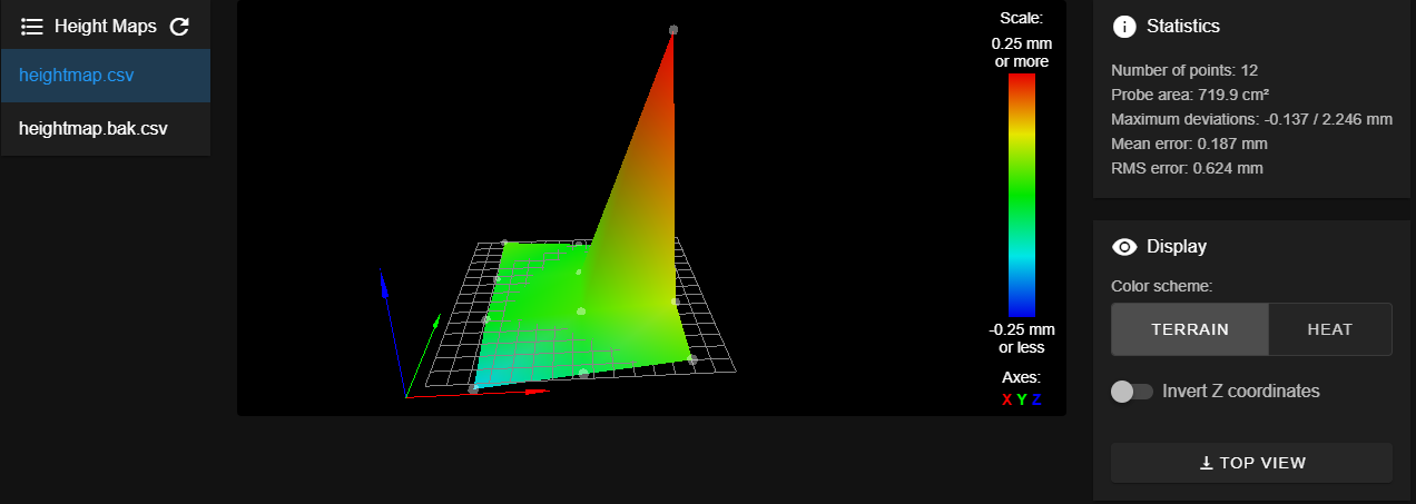
So not sure what direction to go from here. I know my probe is good, but the results of the mesh compensation isn't.
-
@gamefanatic3d is your printer a tool changer with a z probe switch on the head like the E3D one?
Could simply be that the weight of the tools when printing is causing the gantry to sag which won't be measured when you probe -
@engikeneer
Yes, I'm using the tool plates setup from E3D and the BLTouch. The BLTouch is on the opposite side of the rail from the tool head. If the weight were to make a difference it would slightly fall to the side of the tool which would naturally bring it closer to the bed, but I'm experiencing results further. The BLTouch would move away due to the twisting action, but I never measure with a Tool on since there is never enough clearance. I had thought about this, but the issue is that I can repeatably measure the distance from the bed to the nozzle compared to what DuetWeb / PanelDue is reporting. In either case, I designed my tools such that the weight of the motor was supported by the tool carriage and was nearly evenly distributed across the rail for just this reasoning.I wrote a macro to perform a G30 twice at each spot and calculate the difference from the trigger height and move down the bed after getting an accurate read of the two dives within 0.005. I disabled mesh compensation and went through a full manual bed leveling last night using just my probe to measure the distances and came up with slightly different values than when the mesh compensation routine ran, but the end result was approximately the same.
However, much along the lines of what you have suggested here, I baby stepped -0.16 when running my test and got T0 to accurately lay down the first layer. I'm not sure why this is the case and I haven't tested against T1 as of yet.
-
@fcwilt said in Mesh compensation results backwards:
I would think that if there was some sort of firmware issue that caused the reversal someone would have noticed it by now.
That's the point, this is by far not the first thread reporting such issues with toolchangers... At least two other people (me being one of them) have similar issues... Troubleshooting has so far not been any useful...
-
@gamefanatic3d Can you show how a typical first layer comes out for you? Just some cube or so. I have similar issues with my toolchanger and haven't been able to diagnose the cause yet...
-
@gamefanatic3d said in Mesh compensation results backwards:
However, much along the lines of what you have suggested here, I baby stepped -0.16 when running my test and got T0 to accurately lay down the first layer. I'm not sure why this is the case and I haven't tested against T1 as of yet.
What happens if you do this:
- disable mesh compensation
- set the Z=0 datum at a XY point on the bed where the height map suggests it is quite flat
- move tool 0 to that XY point
- move tool 0 to Z=0
- does the nozzle is just touch the bed?
- move tool 1 to that XY point
- move tool 1 to Z=0
- does the nozzle is just touch the bed?
Frederick
Printers: a E3D MS/TC setup and a RatRig Hybrid. Using Duet 3 hardware running 3.4.6
-
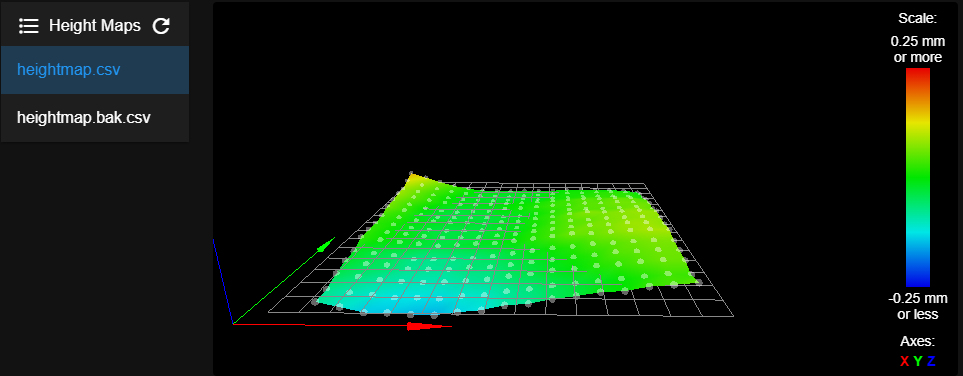
I hadn't been taking pictures of the results but set up a simple single-lined box to test a run of making the first layer and not waste too much filament.
Calibration-Bed-Level-Single-Extrusion-Boxes.stl
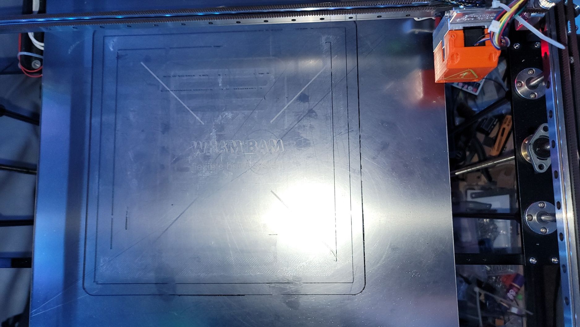
With one of the heightmaps that were generated by the system. You will notice is the image below a lot of areas where the single extrusion lines are missing. This is a result of not getting close enough from what I can tell and as I watched it extrude it would just gather on the nozzle in most cases. Even better, when it actually got something to stick, the slicer thought it best to go back over that line, and low and behold the nozzle would scoop it back up again due to it not barely touching. Here is the result of one such test:
Even after running through my own macro to get the deviations in the bed, I had problems. Now I'm in the process of doing the following:
- Warm the bed and Nozzle to operating temps (Bed: 70°C, Nozzle: 230°C).
- Run G28
- Disable mesh compensation
- Using a feeler gauge manually measure the height of T0 to the bed at my typical 0 location (X200 Y200).
- Move the nozzle to the point on the bed that would normally be measured by the probe and lower it until it just barely touches my feeler gauge.
- Write down the difference in the coordinate on my custom heightmap (feeler gauge is 0.8mm) <feeler gauge height> - <Duet reported Z> = <heightmap value>
Maybe I should have done a smaller height map, but I didn't. It was 3 am and wasn't thinking clearly. I got through the first 3 furthest most Y-Axis rows. I uploaded my slightly modified map and enabled mesh compensation and measured both tools to the feeler gauge at both X200 Y200 and at least one of the points on the map and got approximately a 0 gap. So the method appears to be working, but have a ways to go.
In this image, you can see the right side (bottom of the picture) has a greatly improved first layer. This was using the heightmap I generated using my macro as the basis.

Going forward I need to find my Z-probe tool to make this an easier task and less burning of skin!