Ps-on / PS-off Duet3 6HC
-
If I have a 24V 500W power supply with 4-10V Powerswitch circuit how do I have to connect it to the Duet3 6 HC? Do I need a 5V external connection? Got a 5.2V power supply for my SBC. From that I could go with 5V to the board and from the 24V power supply with - to the power supply and with the + on PS-On on the Duet board. Or do I have to use the + 5V from the power supply to PS-on on the power supply and with - on the board?
-
I don't understand the detail of your power supply (i.e. what you mean by '4-10V Powerswitch circuit') , but what I have is separate 5V and 24V supplies. The 5V is effectively always on and supplies the SBC (I have a Pi4) and also connects to the +5V and GND pins of the'EXT 5V' conenctor on the MB6HC. I have no jumpers on any of the 'power options' jumpers near the middle of the board.
I then take the pson signal to drive a relay board that swicthes the mains voltage to the power supply that's generating the 24V. The gnd and 24V from that supply are connected to the MB6HC 'POWER IN' screw terminals.
Whether this will work directly on your power supply is the bit that is uncertain - the pson signal is designed to work ATX PSUs - when the MB6HC wants to switch the power supply on, it connects the pson pin to ground - so if your supply complies with that it should work. However, if your power supply switches on when a positive voltage is applied to its control line, then you'll need something else external to do that.
-
Little preview of what is to come in 3.4b4 - the gCode wiki has already been updated, so the cat is already out of the bag. No more relay needed for Meanwell power supplies (with built-in pson functionality)! We've been working with the Duet team testing this and it's working beautifully. I'll be assisting with a write-up after 3.4b4 has been released.
M80: ATX Power On
ParametersC"port_name" (RRF 3.4beta4 and later) Name of the pin used to control the power supply, default "pson"
ExamplesM80
M80 C"!pson" ; invert the PS_ON output for Meanwell power supplies
Turns on the ATX power supply from standby mode to fully operational mode using the power supply control pin on the External 5V header. If a deferred power down command was set up using M81 S1 then it is cancelled. -
Thank you for your response. I'm looking forward to testing the whole thing. Is there then also a description of the cabling for the standard connection PS-on? Do you also need the external 5V connection?
-
@heartleander81 Is this a Meanwell power supply? If so, it should not require an external 5v power supply, but you'd need to verify. I'll be assisting with a write-up soon, but real quick - Meanwell's specs are not clear. We worked with one of their engineers to validate and work out the details - at least for the model power supplies we utilize.
The pson terminal on the Meanwell power supplies (that we utilize - probably all, but we can't guarantee this) are actually carrying positive voltage. Check to see if yours is as well. If so, try grounding it to the negative terminal and the power supply should go into standby mode. Meaning it can be operated by a simple switch - or through the Duet by inverting the ps-on signal which is what is upcoming in 3.4b4.
-
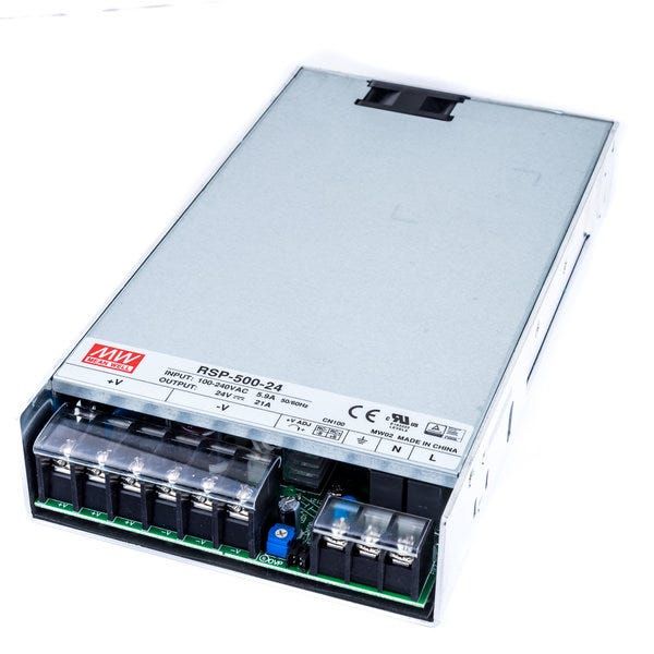
@oozebot I get the RSP 500W 24V the days like in the picture.
Thanks very much. That helps me further. So thank you to the whole Duet team for your work and help.
-
It appears the plug you’ll need is the DF11-4DS-2C and the matching connectors are DF11-2428SC.
-
This post is deleted! -
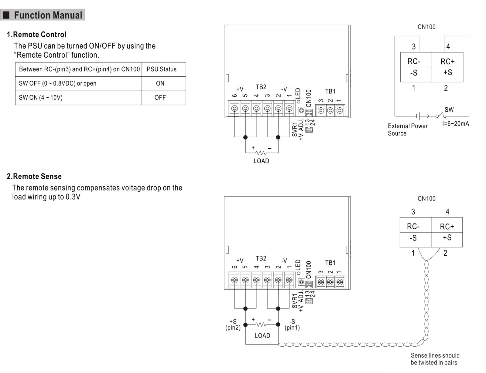
@oozebot Hi. Which contact do you use on the switching power supply? There are 4 connections and unfortunately I have not yet found any instructions from Meanwell which contact is for what. I have RC-, RC +, S- and S +.
-
Must I connect RC+ on pson and RC- on GND on the Duet3 6hc Board?
-
Here is the specifications for your power supply:
https://www.meanwell.com/webapp/product/search.aspx?prod=RSP-500
Here are the important bits:
RC- Return for RC+ signal input
RC+ Turns the output on and off by electrical or dry contact between pin 4 ( RC+) and pin 3 (RC-). 0~0.8VDC or open: Power ON, 4~10VDC: Power OFF
This Power Supply is a bit different than the models we use, but it's similar. I'd start by seeing if RC+ is carrying voltage. I suspect it is. If so, try connecting it to RC- to see if that sinks RC+ to ground and turns off the Power. I suspect it will. If so, to control your power supply, you will need to sink RC+ to ground to turn off power and then unsink it to turn it back on.
By tying the grounds between the 5v and 24v power supplies, you can then control your 24v power supply by sinking RC+ to PSON on the Duet board when used in conjunction with M80 C"!pson"
-
@oozebot
Hi. Rc+ to gnd 0V RC- to gnd 0V -
I have this found
If I understand correctly I need an external + 5V and GND to switch it.
-
@heartleander81 All models we tested worked a bit different, but I think you are right. I just read this:
POWER OFF: 4~10VDC between RC+(Pin 4)&RC-(Pin3) on CN100So try tying the negative terminals between power supplies and then applying 5v to RC+ to turn off the power supply.
-
@oozebot ok. Then I can connect +5V on RC+ and RC- on pson. Right?
-
@heartleander81 I think you should do some testing between the two power supplies first to validate. If it works, then I believe you are right.
-
@oozebot I connected RC + 5v and RC- to GND but the power supply did not switch off. I'm afraid that my power supply has a fault. I contacted Meanwell to see if they can give me information on how I can test whether my power supply has a fault or not because it does not work as described in the instructions
-
@heartleander81 Sorry to hear that - that model appears to work differently than many of the others. Where the two power supplies negative terminals tied together?
-
@oozebot I can already find a solution
") I hope Meanwell answers promptly so that I can find out and possibly make a repair or get an exchange because it has a 3 year guarantee.
I hope Meanwell answers promptly so that I can find out and possibly make a repair or get an exchange because it has a 3 year guarantee. -
@oozebot I doun't know why, but now is it work.
I think it was a Bad connection on the power supply.