Duet3D Logo Duet3D
    • Tags
    • Documentation
    • Order
    • Register
    • Login

    4 endstops for 4 z stepper motor and 3D Touch possible?

    Scheduled Pinned Locked Moved
    Firmware installation
    5
    16
    639
    Loading More Posts
    • Oldest to Newest
    • Newest to Oldest
    • Most Votes
    Reply
    • Reply as topic
    Log in to reply
    This topic has been deleted. Only users with topic management privileges can see it.
    • Phaedruxundefined
      Phaedrux Moderator
      last edited by

      Are you perhaps getting some interference with the wiring for that endstop?

      How can you tell that io2.in is always activated?

      Z-Bot CoreXY Build | Thingiverse Profile

      Duncanundefined 1 Reply Last reply Reply Quote 0
      • Duncanundefined
        Duncan @Phaedrux
        last edited by

        @phaedrux because triggered is = true always and I have nothing connected to io2.in or any line in configuration with io2.in...

        That's why I don't understand why appears the 2 port on endstops if I'm setting the Z with io3, io4, io5, and io6 inputs for the 4 stepper motors.

        jay_s_ukundefined 1 Reply Last reply Reply Quote 0
        • jay_s_ukundefined
          jay_s_uk @Duncan
          last edited by

          @duncan the number 2 doesn't correspond to IO2, it corresponds to the 3 endstop created for the system (when the numbering starts at 0). In this instance, thats your endstop(s) for z

          Owns various duet boards and is the main wiki maintainer for the Teamgloomy LPC/STM32 port of RRF. Assume I'm running whatever the latest beta/stable build is

          Duncanundefined 1 Reply Last reply Reply Quote 0
          • Duncanundefined
            Duncan @jay_s_uk
            last edited by

            @jay_s_uk but I have 4 endstops defined

            M574 Z1 S1 P"io3.in+io4.in+io5.in+io6.in"
            

            So it's not possible to see the status of each endstop when we use more than one for one axis?

            Then I think the problem is that the one on io5.in that is the motor number 4

            M584 X40.0 Y41.0 Z1:2:4:5 E20.0
            

            appears to be always triggered...

            jay_s_ukundefined 1 Reply Last reply Reply Quote 0
            • jay_s_ukundefined
              jay_s_uk @Duncan
              last edited by

              @duncan they are for a global axis though, not 4 individual axes.
              If you unplug the endstop on IO5 does it no longer show as triggered?
              Does it then show as triggered when pressing each endstop?
              If it does show as not triggered when IO5 is connected then I would be investigating the wiring on that endstop

              Owns various duet boards and is the main wiki maintainer for the Teamgloomy LPC/STM32 port of RRF. Assume I'm running whatever the latest beta/stable build is

              Duncanundefined 1 Reply Last reply Reply Quote 0
              • Duncanundefined
                Duncan @jay_s_uk
                last edited by

                @jay_s_uk when I disconnect one endstop from the board is always triggered to true in normal case.

                I tried disconnecting io5 and remains true, and disconnected all other 3 endstops and is true (that's normal), it was supposed to be false if they're connected and all working good.

                So I really don't know where is the error, because the config file seems to be ok as far as I know...

                jay_s_ukundefined 1 Reply Last reply Reply Quote 0
                • jay_s_ukundefined
                  jay_s_uk @Duncan
                  last edited by

                  @duncan what type of endstops are they?
                  How do you have the cables connected?
                  can you post a photo of the wiring at the endstop end?

                  Owns various duet boards and is the main wiki maintainer for the Teamgloomy LPC/STM32 port of RRF. Assume I'm running whatever the latest beta/stable build is

                  Duncanundefined 1 Reply Last reply Reply Quote 0
                  • Duncanundefined
                    Duncan @jay_s_uk
                    last edited by Duncan

                    @jay_s_uk endstops are this https://www.digikey.es/product-detail/es/panasonic-industrial-automation-sales/PM-Y44/1110-2019-ND/3899551

                    the connection is this:
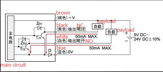
 ccm_sensor_en.jpg

                    brown +V -> 5V_EXT
                    blue 0V - > GND
                    black output 1 LIGHT ON -> ioX.in

                    Wiring should be ok because X and Y axis are working fine... problem seems to be on the use of 4 pcs of endstops for one axis...

                    jay_s_ukundefined 1 Reply Last reply Reply Quote 0
                    • oliofundefined
                      oliof
                      last edited by

                      M584 X40.0 Y41.0 Z1:2:4:5 E20.0

                      Is this correct? Do you have X and Y on separate toolboards?

                      <>RatRig V-Minion Fly Super5Pro RRF<> V-Core 3.1 IDEX k*****r <> RatRig V-Minion SKR 2 Marlin<>

                      Duncanundefined 1 Reply Last reply Reply Quote 0
                      • jay_s_ukundefined
                        jay_s_uk @Duncan
                        last edited by

                        @duncan are they all getting 5v and do the lights all go fully off (or on) when activated and not just dim?

                        Owns various duet boards and is the main wiki maintainer for the Teamgloomy LPC/STM32 port of RRF. Assume I'm running whatever the latest beta/stable build is

                        1 Reply Last reply Reply Quote 0
                        • Duncanundefined
                          Duncan @oliof
                          last edited by

                          @oliof yes, I have two extension boards, those motors and endstops are working fine, they have their own external control drivers.

                          @jay_s_uk yes, lights are working ok, now I have a differente situation I'm going to explain.

                          I put a backup of the config files before using 4 endstops for Z axis and only the probe for Z that was working fine, so machine was working good. Then I updated only the config.g with the one defined with 4 endstops and still good... all motors of Z moving and homming with the probe...

                          When I put the latest homez.g file the problem was again in the machine, so I made this change:

                          This is the homez.g with the initial problems

                          ; homez.g
                          ; called to home the Z axis
                          ;
                          ; generated by RepRapFirmware Configuration Tool v3.1.4 on Fri Sep 04 2020 14:49:01 GMT+0800 (中国标准时间)
                          G91              ; relative positioning
                          G1 H2 Z10 F6000   ; lift Z relative to current position
                          ;G1 H2 X510 Y510 F6000 ; go to first probe point
                          G1 H1 Z-99999
                          G90              ; absolute positioning
                          G30              ; home Z by probing the bed - activar 3D Touch
                          
                          ; Uncomment the following lines to lift Z after probing
                          ;G91             ; relative positioning
                          ;G1 Z10 F100      ; lift Z relative to current positiond
                          ;G90             ; absolute positioning
                          

                          This is the actual homez.g working somehow...

                          ; homez.g
                          ; called to home the Z axis
                          ;
                          ; generated by RepRapFirmware Configuration Tool v3.1.4 on Fri Sep 04 2020 14:49:01 GMT+0800 (中国标准时间)
                          G91              ; relative positioning
                          G1 H2 Z10 F300   ; lift Z relative to current position
                          G90              ; absolute positioning
                          G1 X510 Y510 F10000 ; go to first probe point
                          G1 H1 Z-99999
                          ;G1 X510 Y510 F3000 ; go to first probe point
                          G30              ; home Z by probing the bed
                          
                          ; Uncomment the following lines to lift Z after probing
                          ;G91             ; relative positioning
                          ;G1 Z10 F300      ; lift Z relative to current positiond
                          ;G90             ; absolute positioning
                          

                          So the only main change is that I put G90 before the first probe point movement and Z axis moving down looking for endstops... (but not for the probe touching).

                          So I'm going to test now if once the machine hits the 4 endstops then go for the probe to touch the bed, that it's my objective, because I want to use the 4 endstops to calibrate the machine at the same heigh and then the probe for fine compensation of the bed.

                          But I don't know if that will work if all the movement on Z is on negative direction or I should put the 4 endstops on Z positive and probe for Z negative...

                          1 Reply Last reply Reply Quote 0
                          • First post
                            Last post
                          Unless otherwise noted, all forum content is licensed under CC-BY-SA