Tripod bed mount angle?
-
Hi guys,
I asked this in my hashPrinter thread, but got no feedback. So here's the question again:@o_lampe said in #- (hash) printer with super simple gantry:
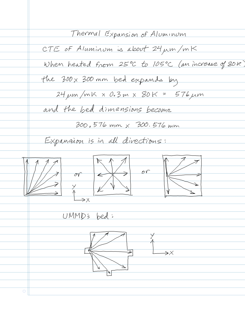
I want to design a tripod bed mount where the bed rests on three ballstuds sliding on dowel-pins to allow temp-expansion.
I"ve seen this on other printers, but I'm unsure about the angles of the dowel pins?
Q: Should they aim to the bed-center, or should I place them at equal angles?
Here's a sketch of the angles in question
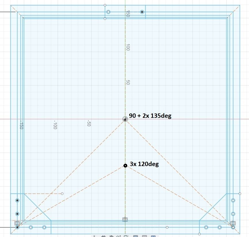 Bed angles
 -
@o_lampe I would prefer the solution with "90 + 2x150deg". Because i think, it's better adjustable. But i have no experience with this kind of bed mount...
-
You're essentially asking about the difference between a Kelvin and a Maxwell kinematic coupling.
The "rails" have to run parallel to the direction that the plate expands, relative to the chosen reference point. The reference point location relative to the adjustments is what makes it a Kelvin or Maxwell coupling.
If you choose the reference point to be the center of the bed, the "rails" should be aligned to point at the center of the bed at all three support points because the bed expands outward in all directions from there. That's the classic Maxwell coupling.
OTOH, if you choose one of the screws to be the reference point, say one of the two along the bottom edge, that point won't need rails- just a "hole" to sit in. The rails at the other point along the bottom edge will simply be parallel to the bottom edge (in your drawing) of the plate, and the third will just support the flat bottom of the plate and is allowed to slide in X and Y. You'll adjust the bottom edge point first to set the edge of the plate parallel to printer's X axis, and then set roll using the third point to set the plate parallel to printer's Y axis. This is a Kelvin mount.
The Kelvin mount's square angles are easier to set up accurately - most machine tools are square- than the odd angles that will result if you choose the reference to be any other point (as in a Maxwell mount), and you only need "rails" at one point, not all three.
If the rails are set square to each other (Kelvin style) and the lines they define are parallel to the X and Y axes of the printer, leveling the bed is super easy because a) you'll only need to adjust two leveling points and b) when you make the adjustments all tilting will be in the directions of the X and Y axes of the printer.
I used a Kelvin mount in my printer, with the reference being a point on one of the "ears" on the plate:
In the Maxwell mount, every leveling adjustment, tilts the bed in X and Y, so tramming isn't quite as simple. Also, every tramming adjustment moves the reference point vertically, so you have to adjust the Z=0 position once the bed is level. It's only a Maxwell mount if you accurately aim the rails at the reference point. Any error will cause the bed to tilt and move up and down a bit as it heats up.
With the Kelvin mount, the reference point doesn't move vertically when you tram the bed, and each adjustment (provided you adjust pitch first, then roll) only tilts the bed along one axis. That means that when you adjust roll, it doesn't affect the pitch adjustment.
Of course, if you use auto tramming and zeroing, difficulties in adjustment shouldn't matter...
-
@mrehorstdmd
Thanks for the elaborate and exquisite answer. I'd give you two thumbs up, if I could.So, with three Z-motors and a Maxwell mount, I'd need to level in several passes.
I think, I've seen a meta-script that does that already? IIRC it was posted from @dc42 ?The Kelvin mount has advantages for manual leveling, but also needs three different designs for the mount.
-
@o_lampe Actually, with the Maxwell mount, as long as two of the leveling points lie along one of the printer's axes (as you have drawn), leveling should be as easy as it is with the Kelvin mount.
-
Just for information, the Jubilee toolchanger uses Maxwell for the toolchanger and for the bed. But I personally prefer Kelvin, because one point is defined exactly and can be used as reference point which doesn't change with temperature.
-
@joergs5
Kelvin for a toolchanger makes sense. OTOH, a XY-gantry usually refers to endstops, not the bed edges. -
@joergs5 me too. The Maxwell mount requires high accuracy in "aiming" the slot/rails. If one of the rails is off a little, the bed is going to move around as it heats up and there may not be a single stable position for it. That could make resuming a print after a power failure a problem, depending on how much the plate shifts when it reheats. If you use manual leveling, it also means that you may have to relevel with each print- just like you had to do 5 years ago when people were putting 4 "leveling" screws at the corners of their bed plates. If you're going to use autotramming the frequent releveling is a not a problem.
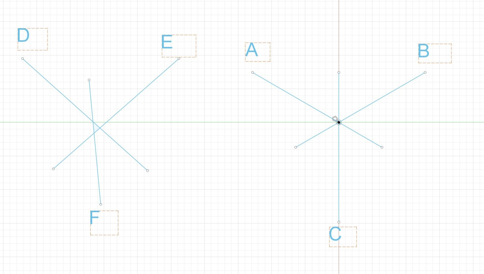
Here's a Maxwell configuration (right side) with accurately placed rails along the lines from each point A,B, and C to the single center reference point. On the left you see what happens when one of the angles is off- there are now 3 "reference" points at the center. Where's the print bed going to go when it heats up? If it starts in the same position when it's cool, when it heats up it it will probably always end up in the same place (but different from where it started when it was cool).
The Kelvin mount defines a specific spot for reference and is easier to make accurately, though as @o_lampe pointed out, it needs 3 "designs" for the adjust/mount points. The designs are a hole, a slot, and nothing (i.e. leave the flat plate alone so it can slide in X and Y). The bed will always expand the same way and end up in the same position every time it heats up (to the same temperature). If there's a straight line between the hole center and the slot, and you align it with the X or Y axis of the printer, which is super easy to ensure compared to making 3 slots at angles like 120 degrees, you're good to go. When I made the bed for my printer, I aligned the edge of the plate with the X axis on a milling machine, then drilled the reference hole, then milled the slot at the opposite side of the plate. When I installed the bed in the machine, I lined the edge of the plate parallel to the printer's X axis. It was all very easy, didn't require a rotary table for the mill (though we have one- I chose not to use it).
-
@o_lampe if one wants to procced a print after an interrupt, I think it's necessary to use a 3d measuring probe or a very precise 3d scanner to locate the object, because endstops are not precise also.
My preference for Kelvin is because of designing a toolchanger to be able to change CNC tools with bigger forces, by using zero-point-systems (german Nullpunktspannsystem), which are similar to the Kelvin system, the one point being in the middle. Imho the toolchangers of E3D/Junior are too weak for CNC. Sideway forces can change the positions of the Maxwell system.
-
@joergs5 Endstops can be precise, especially optical type. A year or so ago I ran a test on my printer after I replaced snap switches with optical endstops in X and Y. I printed identical files, one the normal way and the other rehoming the X and Y axes for each layer. The result was two prints that were nearly identical under magnification. See: https://drmrehorst.blogspot.com/2020/03/testing-ummds-xy-optical-endstops.html
There are two big problems with resuming prints after power failure- first, if the bed cools, the print might let go and there's no recovery from that. Second is the Z axis. The motors are going to move a bit when power is reapplied, and you can't rehome Z while the print is on the bed, so the first layer of the restart may be too thin/thick or even tilted slightly depending on the Z axis configuration.
Now if you throw in a poorly executed Maxwell mount for the bed, the plate may shift a little as it heats up and it may not return to the original position, so you may get a small lateral layer shift (or even rotation) in the print.
-
@mrehorstdmd thank you for some additional ideas (I didn't consider shrinkage eg) what to consider to proceed a print. What I wish to do is not after a power failure primarily, but if I want to add something to an existing print or add a different material. It may be easier to glue it to the object.