Duet3D 1HCL - Closed Loop Controller Beta test
-
@t3p3tony said in Duet3D 1HCL - Closed Loop Controller Beta test:
M569.6 P50.0 V31
9/21/2021, 7:00:28 AM M569.6 P50.0 V31
Error: M569.6: Drive is not in closed loop mode. -
@supertb1 with M569 P50.0 D4 S1 first?
-
@lirwin17 said in Duet3D 1HCL - Closed Loop Controller Beta test:
M569.1 P50.0 T2 C5 E5:10
the motor has a 4000 pulse per rotation that I verified
-
@lirwin17 said in Duet3D 1HCL - Closed Loop Controller Beta test:
M98 P"config.g"
before change to P50.0
9/21/2021, 7:10:36 AM Error: Response timeout: CAN addr 51, req type 6045, RID=27
Pulse-type filament monitor on pin io5.in, enabled, sensitivity 7.000mm/pulse, allowed movement 55% to 150%, check every 22.0mm, no data received
Error: bad model parameters
9/21/2021, 7:10:35 AM Error: Response timeout: CAN addr 51, req type 6043, RID=25
9/21/2021, 7:10:34 AM Error: Response timeout: CAN addr 51, req type 6042, RID=23
9/21/2021, 7:10:33 AM Error: Response timeout: CAN addr 51, req type 6042, RID=21
9/21/2021, 7:10:32 AM Error: Response timeout: CAN addr 51, req type 6042, RID=19
9/21/2021, 7:10:31 AM Error: Response timeout: CAN addr 51, req type 6018, RID=17
9/21/2021, 7:10:30 AM Error: Response timeout: CAN addr 51, req type 6041, RID=15
Error: No encoder specified for closed loop drive mode
9/21/2021, 7:10:29 AM Error: Error threshold value must be greater than zero. -
@supertb1 I have P51.0 disconnected at the moment as advised
-
Short update:
I am on my third print with the closed loop drivers and so far they are working quite well. The axes are sticking to their position very well. I really have to apply a lot of force to push them off course, and they will snap right back.

I am printing with up to 300mm/s and was able to increase my acceleration and jerk significantly. On the downside I had to limit my max. speeds to 20000mm/min or 300mm/s.
@lirwin17 I have two motors on my Y axis. They are both wired to one 1HCL board, but only one has an encoder. It calibrates fine, and I did not spot a significant problem during printing. Only the recorded graphs were of no use on this axis (at least for me). Maybe something to keep in mind for future development.(especially for autotuning.
 )
)Furthermore, I have the impression that the drivers run in full step without any microstepping as soon as I switch to closed loop. It sounds very much like my very first printer.
 The prints also show a strong stepping pattern.
Cheers Max
-
@lirwin17
After change to P50.0
Error: Response timeout: CAN addr 51, req type 6045, RID=27
Pulse-type filament monitor on pin io5.in, enabled, sensitivity 7.000mm/pulse, allowed movement 55% to 150%, check every 22.0mm, no data received
Error: bad model parameters
9/21/2021, 7:14:52 AM Error: Response timeout: CAN addr 51, req type 6043, RID=25
9/21/2021, 7:14:51 AM Error: Response timeout: CAN addr 51, req type 6042, RID=23
9/21/2021, 7:14:50 AM Error: Response timeout: CAN addr 51, req type 6042, RID=21
9/21/2021, 7:14:49 AM Error: Response timeout: CAN addr 51, req type 6042, RID=19
9/21/2021, 7:14:48 AM Error: Response timeout: CAN addr 51, req type 6018, RID=17
9/21/2021, 7:14:47 AM Error: Response timeout: CAN addr 51, req type 6041, RID=15
9/21/2021, 7:14:43 AM M98 P"config.g"
HTTP is enabled on port 80
FTP is disabled
TELNET is disabled
Again channel 51 is disconnected -
@t3p3tony
G4 S3 ;wait for expansion boards to start
M569.1 P50.0 T2 C5 E5:10 ; Configure the 1HCL board at CAN address 50 with a quadrature encoder on the motor shaft that has 20 steps per motor full step.
M569.M51 P51.0 S1 T2 C20 E20 R100 I0 D0 ; Configure the 1HCL board at CAN address 51 with a quadrature encoder on the motor shaft that has 20 steps per motor full step.
M569 P50.0 D4 S1 ; Configure the motor on the 1HCL at can address 50 as being in closed-loop drive mode (D4), Open loop (D2) and not reversed (S1) X axis
M569 P51.0 D2 S1 ; Configure the motor on the 1HCL at can address 51 as being in closed-loop drive mode (D4), Open loop (D2) and not reversed (S1) Y axis
M569 P0.0 S1 ; physical drive 0.0 goes forwards Z 1-2 axis -
@supertb1 sorry I should have been clearer. After start up send the following from the console:
M569 P50.0 D4 S1 M569.6 P50.0 V31 -
@lirwin17
since the change on the M569.1 line to P50.0 T2 C5 E5:10
I am now getting closed loop enabled : yes
on P50 V8 it is saying that the drive has an incorrect polarity
V32 made the drive run off to the end of it's travel
M569.6 P50.0 V64
Warning: No new tuning errors have been found, but some existing tuning errors exist. The drive has not been zeroed. The drive has not had it's polarity checked. The drive has not had it's control checked. The encoder has not had it's count per revolution and V128 is the same result -
@t3p3tony said in Duet3D 1HCL - Closed Loop Controller Beta test:
M569.6 P50.0 V31
M569.6 P50.0 V31
Warning: M569.6: One or more tuning errors occurred. The drive has been found to have an incorrect polarity. -
@t3p3tony does this mean that I need to switch the positive and negative wires?
-
-
does this mean that I need to switch the positive and negative wires?
Sorry, this error message is a bit misleading - I'll change that. The polarity should be detected automatically, so a better error message may be "encoder polarity failed to be detected"
Please could you follow the same instructions I gave to maxgyver above (here), although on the 'movement' checkboxes down the right hand side, please could you check 'polarity detection'
We should then be able to take a look at the graph and see what's going on
")
-
-
@lirwin17 is there another report with different variables I need to run for more information?
-
-
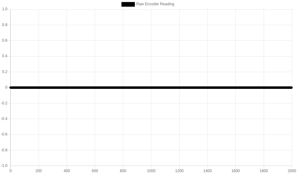
@lirwin17 I'm not sure how to read these... it looks like coil A is out of step phase and coil B doesn't appear to be doing anything... target motor steps says there are 4 errors
-
is there another report with different variables I need to run for more information?
No, this is great

I'm not sure how to read these...
There's docs coming soon, but for now I'll talk you through it
The first thing to say is that the raw encoder reading is 0 on both recordings - this means it doesn't seem to register the encoder as moving at all.
This is strange because I thought that you did M122 twice after manually turning a full rotation and the encoder's reading changed... Please could you confirm this is still the case
(See this post for more detailed information)
-
@maxgyver thank you for the update! Don't worry, I've not forgotten about increasing the max speed - it's actually next on my list!
was able to increase my acceleration and jerk significantly
Excellent that's what we like to hear

I have two motors on my Y axis. They are both wired to one 1HCL board, but only one has an encoder. It calibrates fine, and I did not spot a significant problem during printing. Only the recorded graphs were of no use on this axis (at least for me). Maybe something to keep in mind for future development
Hmm okay
 do you mean that both motors are wired into the single driver output on the 1HCL? What exactly were the issues you were having with the recorded graph?
Furthermore, I have the impression that the drivers run in full step without any microstepping as soon as I switch to closed loop. It sounds very much like my very first printer.
The prints also show a strong stepping pattern.This is an interesting one haha - so with closed loop, we kinda lose all sense of microstepping, since the motors no longer move in discrete steps, but move as close to continuously as possible. This means that in theory, the microstepping is infinite... but the keyword here is 'continuously as possible', in reality the motor has to move some discrete distance per PID iteration, and this is a function of the frequency of the PID loop (constant) and the speed of the move (variable). If you do a very slow move, I'd expect you to be getting very small discrete moves per PID cycle (the equivalent of very high mocrostepping), whereas if we're pushing the boundary on how fast we can move, you'll get very large discrete moves per PID cycle (up to a full step).
You can actually measure the size of these discrete steps by taking a recording (with speed set to 'as fast as possible') and looking at the step phase variable, and the vertical distance between datapoints. A distance of 90 degrees means 1 step, you could work out an 'effective microstepping' from this, since you know the increments in which the motor moves.The good news is though, as we increase the maximum speed, the 'effective microstepping' will also increase as well, so hopefully you'll see less of the stepping pattern as we do so