Self Leveling (3 motor leadscrew) printer = Non-planar printer?
-
@roiki11
As it seems, there are several ways to build a non-planar printer, but would they all be happy with one slicer solution?
E.g.: rotating head vs. tilting bed.
The slicer would dictate how extra printer axes have to be named (eg. A/B), which wouldn't work for all.
IMHO, there has to be a new printer class first and it's requirements dictate the slicer-code.If Prusa decided to develop a non-planar printer, they would also come up with a dedicated slicer. But the benefits of this new type are marginal vs. the effort to make it happen.
-
@visionary I've rotated your triangle now, so D5 is horizontal on top (so I can calculate by the restricted formula of the link I provided), then calculated the midpoint and have xy with two equations. As mathematicians like to say, the rest is trivial.
") , not really.
, not really.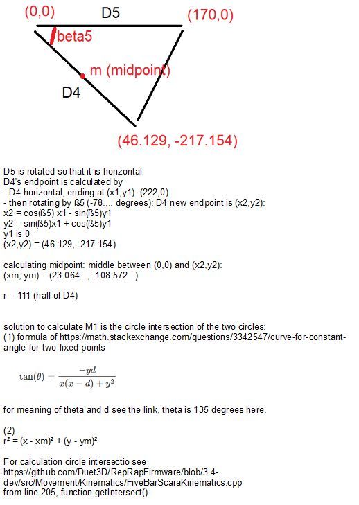
The first formula has an interesting symmetry:
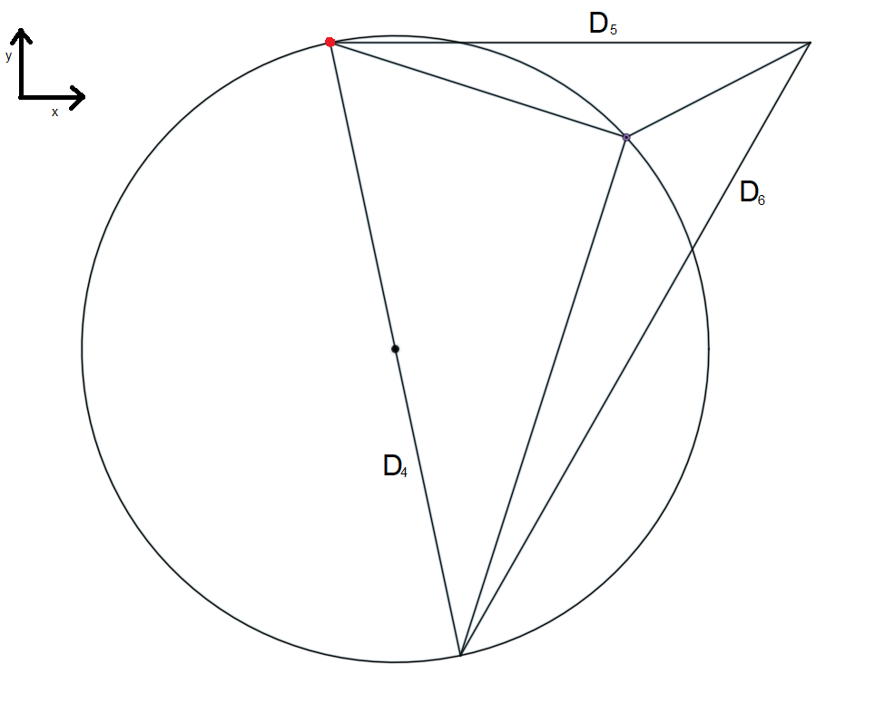
x² + y² = (x + y) dsymmetry doesn't help, as it is the mirroring at the diagonal x=y, and the crossing with the other formula is the low red segment:
(created with online Desmos)
The midpoint is (85,85) and radius is sqrt of 85²+85²= about 120.208
-
Not true. In CNC world the 5 axis programs are supplied as tool vector coordinates (X, Y, Z for the tip, I, J, K for the vectot point) and it's the machine itself that applies the appropriate transformations to run the machine. The CAM software doesn't need any machine specific information to create the code, though specific limitations of individual machines are not taken into account(there's Sim software for that).
The same approach would have to be done on th slicer in order to not lock it for a specific machine configuration that it's designed for. You're right about that.
-
Have you though about looking at Stewart platform kinematics? It's a pretty similar in concept, it just has more movable axes.
-
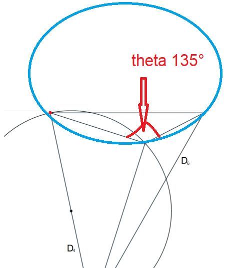
Sorry but I have hard time trying understand your handwriting. Which of the angles is theta?
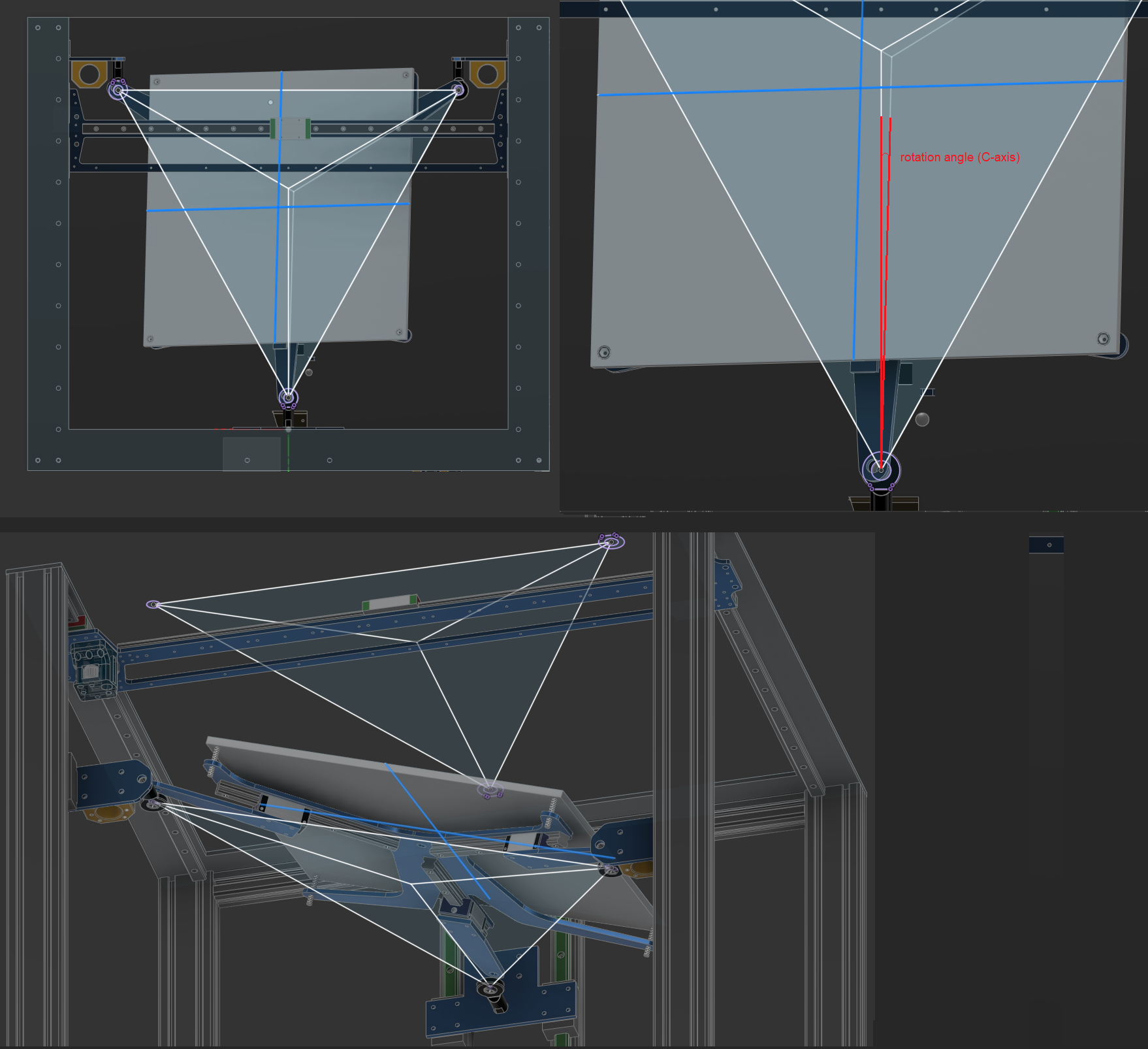
Main printer: 3-5 Axis, 400x400x450 Duet 6HC || https://grabcad.com/eetu-4/models
-
@visionary said in Self Leveling (3 motor leadscrew) printer = Non-planar printer?:
Which of the angles is theta?
theta is the 135 degree angle and is the angle being used in the article https://math.stackexchange.com/questions/3342547/curve-for-constant-angle-for-two-fixed-points at the B point, in the first answer angle ABC.
I know I have an awful handwriting, sorry for that!
-
@roiki11 said in Self Leveling (3 motor leadscrew) printer = Non-planar printer?:
Have you though about looking at Stewart platform kinematics?
I am not the creator of this thread, so it's better to ask @Visionary . I personally know the stewart/hexapod platform and it's interesting. There has been other users trying to implement in RRF already, like in https://forum.duet3d.com/topic/7635/custom-kinematics-on-duet/14 but I think it was not finished, as so many projects.
-
The main reason why kinematics that is explained in this threads might be better than Stewart platform or any traditional way do +5 axes I've seen is that is easy to do mechanically with off the self parts. Machines like it already exist (for example Arnold_R_Clark's machine in this thread), but they still lack kinematics in software for Duet. Stewart machine relies on actuators that are hard to built or are expensive. This thread's kinematics can be used with linear rails or linear rods (though they can be expensive too).
Other pros:
- This bed system that has rotational axes does not have X-and Y-axes. This means X-and Y-axes can have any setup there is (idex, toolchanger,...).
- The system can be used normally with 2,5D slicers and do high quality prints. I assume that some setups for +5 Axes are heavy X/Y-gantries plagued by rigidity and positional accuracy problems (if compared something like Prusa or Voron print quality).
- With Duet 3 6HC no extra boards are needed.
- I happen to have many of the parts for this build.
- Unlike most printer designs, the design I'm aiming for is something that does not have printed parts or machined special parts. Simple plate 5mm aluminum plate parts are super easy to manufacture
Main printer: 3-5 Axis, 400x400x450 Duet 6HC || https://grabcad.com/eetu-4/models
-
@visionary said in Self Leveling (3 motor leadscrew) printer = Non-planar printer?:
hard time trying understand your handwriting
I take criticism seriously
here is to clearify, I've inserted the better explanation in the post above. -
Thanks
 . The angle alpha_a12 is in the drawing that I posted is 90 degrees. All the example values (vectors and coordinates) are for that specific geometry. I'm not sure if you switched that angle to 135 in your calculations. tan(90) is undefined.
The best angles between arms would preferably be either:- 90+135+135
- 120+120+120
Main printer: 3-5 Axis, 400x400x450 Duet 6HC || https://grabcad.com/eetu-4/models
-
@visionary I took 90+135+135 like in your drawing. But my drawing is a bit wrong, the left side is steeper in reality (78° for beta5). Please take D4, D5, beta 5, those are the labels you used in your diagram. Rotation 135 degrees counterclockwise results in my drawing. (the 135 rotation is a guess, I only want to explain how I get from your triangle to mine. The important part is: D5 must be horizontal, so the left point is (0,0) and the right one has y=0, so the formula is applicable).
The calculation of D5 is the curve for the 135° angle which is calculated in formula 1, the midpoint circle of D4 is the 90° triangle which is calculated by r²=x+y². tan(135°) is -1, so the first formula gets simple and results in the circle which I calculated with Desmos. The two circels meet in two points, calculated by getIntersec(), using the correct point is the middle of the green M lines. The vectors from the edges to this midpoint can be used to calculate the lengths.
-
i didn’t mean actual stewart platform, just the kinematics of it since what you’re trying to do is mathematically very similar to it with the two platform rotation axes.
Anyway, a 3 dof parallel platform is a simpler stewart platform. In this diagram, You can count the x1 and y1 rotation axes and you get the height of the point B from the I actuators and trigonometry.
If you look at this Instructables link, i’d think you get what you want when the T vector is the height and is constrained to the base Z vector.
At least thats my understading of the math.
-
@roiki11 said in Self Leveling (3 motor leadscrew) printer = Non-planar printer?:
simpler stewart platform. In this diagram, You c
in the document "Kinematics Analysis and Mechatronics System Design
Of a 3-DOF In-Parallel Actuated Mechanism" of the same author Huynh (it is cited in the article of your drawing), you'll see, that the formulae are similar complex like those discussed here. Same the MICS_Journal_ForwardKinematics.pdf in the instructables page. I read there somewhere that the inverse kinematics is easier than the forward. I don't agree, if you look into https://www.xarg.org/paper/inverse-kinematics-of-a-stewart-platform the inverse kinematics is complex also.The Stewart platform is said to have limited stroke. This kinematic here has more stroke, but it remains to be seen whether it is stable enough.
-
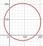
I still can't quite understand the geometry even after looking at the link you've posted.
Where is the other circle center located? (the other circle center is in the middle of D4.)
Could you draw it to for example to picture below? Please put theta there too.
Main printer: 3-5 Axis, 400x400x450 Duet 6HC || https://grabcad.com/eetu-4/models
-
@visionary said in Self Leveling (3 motor leadscrew) printer = Non-planar printer?:
other circle center located
The formula in https://math.stackexchange.com/questions/3342547/curve-for-constant-angle-for-two-fixed-points calculates the blue line. For triangles with 90 ° angle we have sentence of thales, and the meeting point is always on the half circle. The question was, whether there is a similar curve for other angles. The formula is for other angles like 135° and in this case a circle segment.
The solution is the circle intersection between left and upper circle, with two solutions. The fist is at (0,0), the second is the searched solution.
About circle intersection: http://www.ambrsoft.com/TrigoCalc/Circles2/circle2intersection/CircleCircleIntersection.htm (but first graph is wrong, x and y axes wrong).Center of the upper circle is (85,85) and radius sqrt(85²+85²), if the left upper edge of D5 is (0,0).
-
I think I understand the math so far. The geometry results (mainly circle intersection point and M3 arm pointing direction) need to be projected to XY-plane. Bed offset from plane defined by ball joints need to be taken into account as well.
I'm trying to do c++ code for testing the math as these things are figured out too.
Main printer: 3-5 Axis, 400x400x450 Duet 6HC || https://grabcad.com/eetu-4/models
-
@visionary right, I meant this by saying the plane is tilted. I don't know if this is the correct word, but I mean, the XY coordinates of the plane are not the real world coordinates of xyz. Additionally: I think if one edge is lifted, the plane is rotated around the Z axis also a bit (if the two other edges are at different Z levels).