Duet Mini5 wiring diagram in Fritzing?
-
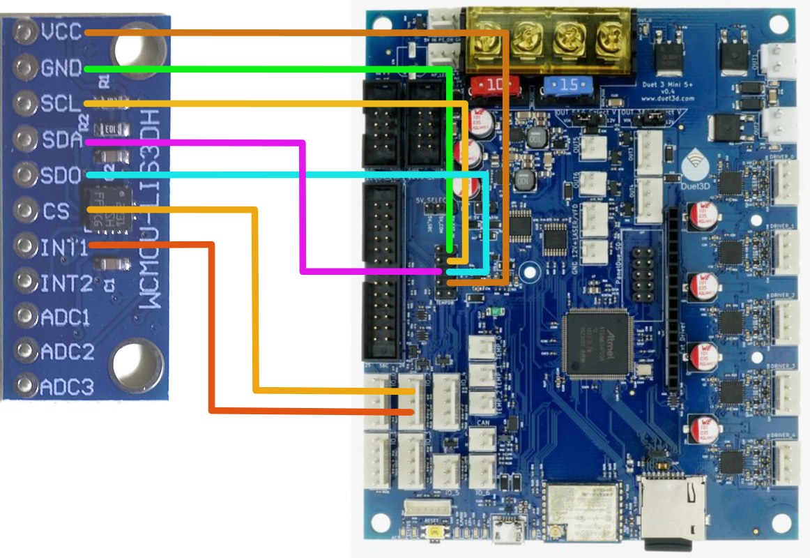
I would like to create a wiring diagram of a Duet Mini5 and an accelerometer sensor. Fritizing seems to be a tool that support similar picture-based wiring diagram but I couldn't figure out how to import the image of the Mini5 as a new component.
Any suggestion for a tool for Duet wiring diagrams? Any idea how to do that in Fritzing?
-
HERE and HERE are some pages showing how to create a new "Part" in Fritzing. (From 2012, so it looks like Fritzing documentation is either fantastit, or unmaintained.
") )
)It sounds like you would import an image of the Mini5 and then define all the connection points on that image and you'd be all set.
Then you could share that "Part" with this and the Fritzing community!
-
Thanks @alankilian, the tutorial seems to focus on line art, do you know how to import an picture of Duet Mini5, and define a few points on it that are connectable to other components?
-
@zapta No, I have no idea how Fritzing works.
But here's what it says in the link:
Loading PNG or JPG images directly is possible, but since these become SVG images
with only a single element, there is no way to place individual connectors.

We also  discourage the use of PNG and JPG because these are raster-based rather
than vector-based, so they don’t look good when scaled. If you still prefer to use
PNG or JPG, we recommend that for now you open them in an external SVG editor
and add connector elements there (see below for more about ‘connector
elements’). Save the result as an SVG, and use that in the Parts Editor.
Also, I would look at some user-supplied parts and start with one that might be close to what you want.
HERE'S one where someone used the tutorials to add a data acquisition "part"
SeemeCNC Rostock Max V3 converted to V3.2 with a Duet2 Ethernet Firmware 3.2 and SE300
-
Thanks @alankilian.
I tried to load PNG 'icons' but got only a gray rectangle when I tried to open that component. Same when I exported a PNG as SVG from inkspace.
Could be a great tool for Duet wiring diagrams but I can't make it to work. I guess the alternative is drop Fritzhing and just use line art overlays in inkscape or similar.
-
@alankilian , I ended up drawing in Inkspace. It keeps the lines as objects so I can easily move them around as needed.