• Tags
  • Documentation
  • Order
  • Register
  • Login
Duet3D Logo Duet3D
  • Tags
  • Documentation
  • Order
  • Register
  • Login

Config for the Pinda v2 ,need help!

Scheduled Pinned Locked Moved
Tuning and tweaking
3
23
1.3k
Loading More Posts
  • Oldest to Newest
  • Newest to Oldest
  • Most Votes
Reply
  • Reply as topic
Log in to reply
This topic has been deleted. Only users with topic management privileges can see it.
  • undefined
    T3P3Tony administrators @lui2004
    last edited by 11 Oct 2021, 17:52

    @lui2004 how is it wired, to what duet?

    www.duet3d.com

    undefined 1 Reply Last reply 11 Oct 2021, 18:17 Reply Quote 0
    • undefined
      martin7404 @lui2004
      last edited by 11 Oct 2021, 18:06

      @lui2004 look here ```
      https://forum.duet3d.com/topic/23566/pinda2-to-duet3-toolboard?_=1633975545248

      Muldex IDEX Duet2+Duex5
      Custom CoreXY 600x400 Hemera , Duet3+Toolboard+1HCL closed loop
      Sapphire Pro with Duet2, with closed-loop motors
      custom high temp E3D tool changer with Duet2+Duex

      undefined 1 Reply Last reply 11 Oct 2021, 18:20 Reply Quote 0
      • undefined
        lui2004 @T3P3Tony
        last edited by lui2004 10 Nov 2021, 18:19 11 Oct 2021, 18:17

        @t3p3tony

        I have:

        Board: Duet 2 WiFi (2WiFi)
        Firmware: RepRapFirmware for Duet 2 WiFi/Ethernet 3.3 (2021-06-15)
        Duet WiFi Server Version: 1.26

        Like this:
        Screenshot_20211011-201653_Adobe Acrobat.jpg

        1 Reply Last reply Reply Quote 0
        • undefined
          lui2004 @martin7404
          last edited by 11 Oct 2021, 18:20

          @martin7404

          This how to is for the duet 3

          undefined 1 Reply Last reply 11 Oct 2021, 18:30 Reply Quote 0
          • undefined
            martin7404 @lui2004
            last edited by 11 Oct 2021, 18:30

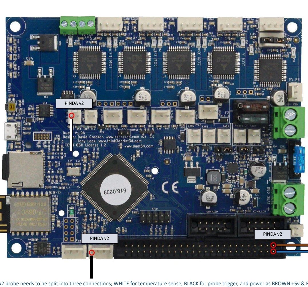
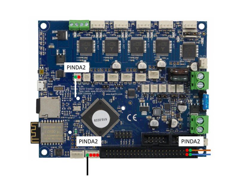
            @lui2004 just use the 0 and signal from the probe and 5V from expansion connector , temp to not used extruder temp

            Muldex IDEX Duet2+Duex5
            Custom CoreXY 600x400 Hemera , Duet3+Toolboard+1HCL closed loop
            Sapphire Pro with Duet2, with closed-loop motors
            custom high temp E3D tool changer with Duet2+Duex

            undefined 2 Replies Last reply 11 Oct 2021, 18:46 Reply Quote 0
            • undefined
              martin7404
              last edited by martin7404 10 Nov 2021, 18:32 11 Oct 2021, 18:32

              https://forum.duet3d.com/topic/22695/pinda-2-config-duet-2-wifi

              Muldex IDEX Duet2+Duex5
              Custom CoreXY 600x400 Hemera , Duet3+Toolboard+1HCL closed loop
              Sapphire Pro with Duet2, with closed-loop motors
              custom high temp E3D tool changer with Duet2+Duex

              1 Reply Last reply Reply Quote 0
              • undefined
                lui2004 @martin7404
                last edited by 11 Oct 2021, 18:46

                @martin7404

                Are you german?
                If yes can you explane me in german ?

                1 Reply Last reply Reply Quote 0
                • undefined
                  lui2004 @martin7404
                  last edited by 11 Oct 2021, 18:46

                  @martin7404
                  What is the 0?
                  I use only 3 wire? The temp wire ist not in use?

                  undefined 1 Reply Last reply 12 Oct 2021, 03:43 Reply Quote 0
                  • undefined
                    martin7404 @lui2004
                    last edited by martin7404 10 Dec 2021, 05:24 12 Oct 2021, 03:43

                    @lui2004 sorry I am Bulgarian .
                    So generaly you ahve 3 wires +5V,- and Signal.

                    • and Sig are conected to - and sig on probe conector and 5V to some 5V pin on the board

                    Muldex IDEX Duet2+Duex5
                    Custom CoreXY 600x400 Hemera , Duet3+Toolboard+1HCL closed loop
                    Sapphire Pro with Duet2, with closed-loop motors
                    custom high temp E3D tool changer with Duet2+Duex

                    undefined 1 Reply Last reply 12 Oct 2021, 06:04 Reply Quote 0
                    • undefined
                      lui2004 @martin7404
                      last edited by 12 Oct 2021, 06:04

                      @martin7404 like this:

                      N6bfUHHquGexwHIG.jpeg

                      and config:

                      ; PINDA2
                      ;
                      M558 P5 C"zprobe.in" H1.5 F1000 T12000 A3 ; set Z probe to PINDA2
                      M308 S2 P"e1temp" A"Pinda V2" Y"thermistor" T100000 B3950 ; temperature of PINDA2

                      undefined 1 Reply Last reply 12 Oct 2021, 08:10 Reply Quote 0
                      • undefined
                        T3P3Tony administrators @lui2004
                        last edited by 12 Oct 2021, 08:10

                        @lui2004 that looks correct and the config matches the wiring. As always when you test the trigger for the first time first confirm not is triggering as expected by manually lowering the Z axis so it's not the expected trigger height and checking the z probe is shown as switching in DWC

                        www.duet3d.com

                        undefined 1 Reply Last reply 12 Oct 2021, 10:12 Reply Quote 0
                        • undefined
                          lui2004 @T3P3Tony
                          last edited by 12 Oct 2021, 10:12

                          @t3p3tony

                          after i do a Dynamic test

                          the pinda v2 wont stop it will crash into the bed

                          undefined 1 Reply Last reply 12 Oct 2021, 10:25 Reply Quote 0
                          • undefined
                            T3P3Tony administrators @lui2004
                            last edited by 12 Oct 2021, 10:25

                            @lui2004 if you move the probe down manually do you see the Zprobe indication on DWC change. What is it showing?

                            www.duet3d.com

                            undefined 1 Reply Last reply 12 Oct 2021, 11:31 Reply Quote 0
                            • undefined
                              lui2004 @T3P3Tony
                              last edited by 12 Oct 2021, 11:31

                              @t3p3tony

                              the pinda wont trigger because i have a pei surface.

                              i have insert some Aluminum foil under the pei i now it will work.

                              which surface is good without Aluminum foil under pei ?

                              undefined 1 Reply Last reply 12 Oct 2021, 11:36 Reply Quote 0
                              • undefined
                                T3P3Tony administrators @lui2004
                                last edited by 12 Oct 2021, 11:36

                                @lui2004 whats the PEI surface mounted on? I suppose most people using PINDA style probes an aluminium bed.

                                www.duet3d.com

                                undefined 1 Reply Last reply 12 Oct 2021, 12:53 Reply Quote 0
                                • undefined
                                  lui2004 @T3P3Tony
                                  last edited by lui2004 10 Dec 2021, 13:01 12 Oct 2021, 12:53

                                  @t3p3tony

                                  aluminium bed with pei

                                  this is my heightmap:

                                  RepRapFirmware height map file v2 generated at 2021-10-12 14:59, min error -0.093, max error 0.125, mean 0.003, deviation 0.049
                                  axis0,axis1,min0,max0,min1,max1,radius,spacing0,spacing1,num0,num1
                                  X,Y,10.00,220.00,10.00,220.00,-1.00,20.00,20.00,11,11
                                  0, 0, 0, 0, 0, 0, 0, 0, 0, 0, 0
                                  0, 0, 0, 0.008, -0.000, 0.091, 0.057, -0.005, 0.050, 0.050, 0.007
                                  0, 0, 0, -0.000, -0.025, 0.082, 0.087, 0.050, 0.032, 0.091, -0.009
                                  0, 0, 0, -0.018, 0.025, 0.116, 0.125, 0.012, 0.007, 0.082, -0.025
                                  0, 0, 0, -0.025, 0.016, 0.116, 0.125, -0.018, 0.032, -0.005, -0.050
                                  0, 0, 0, -0.043, -0.025, 0.041, 0.025, -0.009, -0.018, 0.025, -0.084
                                  0, 0, 0, -0.050, -0.075, -0.034, -0.018, -0.000, -0.000, -0.000, -0.059
                                  0, 0, 0, -0.050, -0.038, -0.034, -0.021, -0.018, -0.018, 0.037, -0.059
                                  0, 0, 0, -0.055, -0.050, -0.043, 0.025, -0.018, -0.034, -0.055, -0.093
                                  0, 0, 0, -0.063, -0.034, 0.032, 0.025, 0.016, -0.009, 0.020, -0.050
                                  0, 0, 0, -0.030, -0.025, 0.007, -0.000, 0.025, 0.025, 0.050, 0.041
                                  1 Reply Last reply Reply Quote 0
                                  • undefined
                                    lui2004
                                    last edited by 13 Oct 2021, 19:16

                                    I bought a new surface !

                                    what is important to calibrate the pinda V2 ?

                                    1 Reply Last reply Reply Quote 0
                                    • undefined
                                      lui2004
                                      last edited by 14 Oct 2021, 03:00

                                      This is my actuall config.g

                                      ; Configuration file for Duet WiFi (firmware version 1.21)
                                      ; executed by the firmware on start-up
                                      ;
                                      ; generated by RepRapFirmware Configuration Tool v2 on Tue May 07 2019 23:06:50 GMT+0100 (British Summer Time)
                                      ; General preferences
                                      G90 ; Send absolute coordinates...
                                      M83 ; ...but relative extruder moves
                                      ; Network
                                      M550 P"Ender 5" ; Set machine name
                                      M552 S1 ; Enable network
                                      M586 P0 S1 ; Enable HTTP
                                      M586 P1 S0 ; Disable FTP
                                      M586 P2 S0 ; Disable Telnet
                                      ; Drives
                                      M569 P0 S1 ; Physical drive 0 goes forwards
                                      M569 P1 S1 ; Physical drive 1 goes forwards
                                      M569 P2 S0 ; Physical drive 2 goes backwards
                                      M569 P3 S1 ; Physical drive 3 goes forwards
                                      M584 X0 Y1 Z2 E3 ; set drive mapping
                                      M350 X16 Y16 Z16 E16 I1 ; configure microstepping with interpolation
                                      M92 X80.00 Y80.00 Z400.00 E288.30 ; set steps per mm
                                      M566 X600.00 Y600.00 Z60.00 E300.00 ; set maximum instantaneous speed changes (mm/min)
                                      M203 X9000.00 Y9000.00 Z600.00 E6000.00 ; set maximum speeds (mm/min)
                                      M201 X500.00 Y500.00 Z100.00 E5000.00 ; set accelerations (mm/s^2)
                                      M906 X800 Y800 Z800 E1400 I30 ; set motor currents (mA) and motor idle factor in per cent
                                      M84 S30
                                      ; Axis Limits
                                      M208 X0 Y0 Z0 S1 ; set axis minima
                                      M208 X235 Y235 Z250 S0 ; set axis maxima
                                      ; Endstops
                                      M574 X1 S1 P"xstop" ; configure active-high endstop for low end on X via pin xstop
                                      M574 Y1 S1 P"ystop" ; configure active-high endstop for low end on Y via pin ystop
                                      M574 Z1 S2 ; configure Z-probe endstop for low end on Z
                                      ;Filament Sensors
                                      M591 D0 P2 C"!e0_stop" S1 ;Extruder 1(0)
                                      ; PINDA2
                                      ;M558 P5 C"^zprobe.in" H1.5 F1000 T12000 A3 ; set Z probe to PINDA2
                                      M558 K0 P8 C"^zprobe.in" I1 H2 F1000 T6000 A20 S0.005 ; set Z probe type to effector and the dive height + speeds, max number of probes per point, tolerance(MM)
                                      M308 S2 P"e1temp" A"Pinda V2" Y"thermistor" T100000 B3950 ; temperature of PINDA2
                                      G31 P500 X52.7 Y18 Z1.775 ; set Z probe trigger value, offset and trigger height
                                      M557 X10:210 Y10:210 S20 ; define mesh grid
                                      ;M557 X41.2:219 Y15:195 S20
                                      ;M671 X28.8:198.8:198:28.8 Y24:24:194:194 P0.5
                                      M557 X10:220 Y10:220 S20
                                      ; Heaters
                                      M308 S0 P"bedtemp" Y"thermistor" T100000 B3950 ; configure sensor 0 as thermistor on pin bedtemp
                                      M950 H0 C"bedheat" T0 ; create bed heater output on bedheat and map it to sensor 0
                                      M307 H0 B0 S1.00 ; disable bang-bang mode for the bed heater and set PWM limit
                                      M140 H0 ; map heated bed to heater 0
                                      M143 H0 S120 ; set temperature limit for heater 0 to 120C
                                      M308 S1 P"e0temp" Y"thermistor" T100000 B4725 C7.06e-8; configure sensor 1 as thermistor on pin e0temp
                                      M950 H1 C"e0heat" T1 ; create nozzle heater output on e0heat and map it to sensor 1
                                      M143 H1 S280 ; set temperature limit for heater 1 to 300C
                                      M307 H1 B0 S1.00
                                      ; Fans
                                      M950 F0 C"fan0" Q500 ; create fan 0 on pin fan0 and set its frequency
                                      M106 P0 S0 H-1 ; set fan 0 value. Thermostatic control is turned off
                                      M950 F1 C"fan1" Q500 ; create fan 1 on pin fan1 and set its frequency
                                      M106 P1 S1 H1 T45 ; set fan 1 value. Thermostatic control is turned on
                                      ; Tools
                                      M563 P0 D0 H1 ; Define tool 0 S3D
                                      G10 P0 X0 Y0 Z0 ; Set tool 0 axis offsets
                                      G10 P0 R0 S0 ; Set initial tool 0 active and standby temperatures to 0C
                                      ; Automatic saving after power loss is not enabled
                                      ; Custom settings are not configured
                                      M575 P1 S1 B57600 ; enable support for PanelDue
                                      M572 D0 S0.05 ; Pressure Advance PLA
                                      ;M572 D0 S0.08 ; Pressure Advance PLA
                                      M207 S1.50 R0 F2100 T2100 Z0 ; Firmware Retraction P0 S0.45 R0 F2100 T2100 Z0 ; Firmware Retraction
                                      M204 P500 T2000
                                      T0 ; Sets Tool0 as default
                                      M501

                                      homeall.g

                                      ; homeall.g
                                      ; called to home all axes
                                      ;
                                      ; generated by RepRapFirmware Configuration Tool v3.1.4 on Tue Jul 28 2020 08:52:12 GMT+0200 (Mitteleuropäische Sommerzeit)
                                      G91 ; relative mode
                                      G1 H2 Z4 F200 ; raise head 4mm
                                      G1 H1 X-240 Y-240 F3000 ; move up to 240mm in the -X and -Y directions until the homing switches are triggered
                                      G1 H2 X4 Y4 F600; move slowly 6mm in +X and +Y directions
                                      G1 H1 X-10 Y-10 ; move up to 10mm in the -X and -Y directions until the homing switches are triggered
                                      G90 ; back to absolute mode
                                      G1 X57.3 Y92 F2000 ; put head over the centre of the bed, or wherever you want to probe
                                      G30 ; lower head, stop when probe triggered and set Z to trigger height

                                      ; homex.g

                                      ; homex.g
                                      ; called to home the X axis
                                      ;
                                      ; generated by RepRapFirmware Configuration Tool v2 on Tue May 07 2019 23:06:50 GMT+0100 (British Summer Time)
                                      G91 ; relative mode
                                      G1 H2 Z4 F200 ; raise head to avoid dragging nozzle over the bed
                                      G1 H1 X-240 F3000 ; move up to 240mm in the +X direction, stopping if the homing switch is triggered
                                      G1 X-4 F600 ; move slowly 4mm in the -X direction
                                      G1 H1 X10 ; move slowly 10mm in the +X direction, stopping at the homing switch
                                      G1 H2 Z-4 F200 ; lower the head again
                                      G90 ; back to absolute mode

                                      homey.g

                                      ; homey.g
                                      ; called to home the Y axis
                                      ;
                                      ; generated by RepRapFirmware Configuration Tool v2 on Tue May 07 2019 23:06:50 GMT+0100 (British Summer Time)
                                      G91 ; relative mode
                                      G1 H2 Z4 F200 ; raise head to avoid dragging nozzle over the bed
                                      G1 H1 Y-240 F3000 ; move up to 240mm in the -X direction, stopping if the homing switch is triggered
                                      G1 X4 F600 ; move slowly 4mm in the +X direction
                                      G1 H1 X-10 ; move slowly 10mm in the -X direction, stopping at the homing switch
                                      G1 H2 Z-4 F200 ; lower the head again
                                      G90 ; back to absolute mode

                                      homez.g

                                      ; homez.g
                                      ; called to home the Z axis
                                      ;
                                      ; generated by RepRapFirmware Configuration Tool v3.1.4 on Tue Jul 28 2020 08:52:37 GMT+0200 (Mitteleuropäische Sommerzeit)
                                      G91 ; relative positioning
                                      G1 H2 Z5 F6000 ; lift Z relative to current position
                                      G90 ; absolute positioning
                                      G1 X57.3 Y92 F6000 ; go to first probe point
                                      G30 ; home Z by probing the bed

                                      thanks for help

                                      1 Reply Last reply Reply Quote 0
                                      • undefined
                                        lui2004
                                        last edited by lui2004 14 Oct 2021, 09:23

                                        Hi

                                        Is there a how to ,to set z offset on different temperature? Like in marlin?

                                        undefined 1 Reply Last reply 14 Oct 2021, 13:26 Reply Quote 0
                                        • undefined
                                          T3P3Tony administrators @lui2004
                                          last edited by 14 Oct 2021, 13:26

                                          @lui2004 there is not the option of using a table like i think Marlin has. You configure the S and C parameters within G31 to compensate:
                                          https://duet3d.dozuki.com/Wiki/G31

                                          Based on this thread:
                                          https://forum.duet3d.com/topic/16972/pinda-2-probe-with-temperature-compensation/5?_=1593546022132

                                          It appears the non linearity of the measurements at different temperatures could be a problem.

                                          The poster in that post shows a conditional gcode way to get around the problem. Before you do that it would be worth testing you can get a good z probe performance with everything (including the PINDA temperature) at a steady temperature.

                                          Once thats working then non linear temperature compensation can be looked at,

                                          www.duet3d.com

                                          undefined 1 Reply Last reply 14 Oct 2021, 15:13 Reply Quote 0
                                          11 out of 23
                                          • First post
                                            11/23
                                            Last post
                                          Unless otherwise noted, all forum content is licensed under CC-BY-SA