sensor ir
-
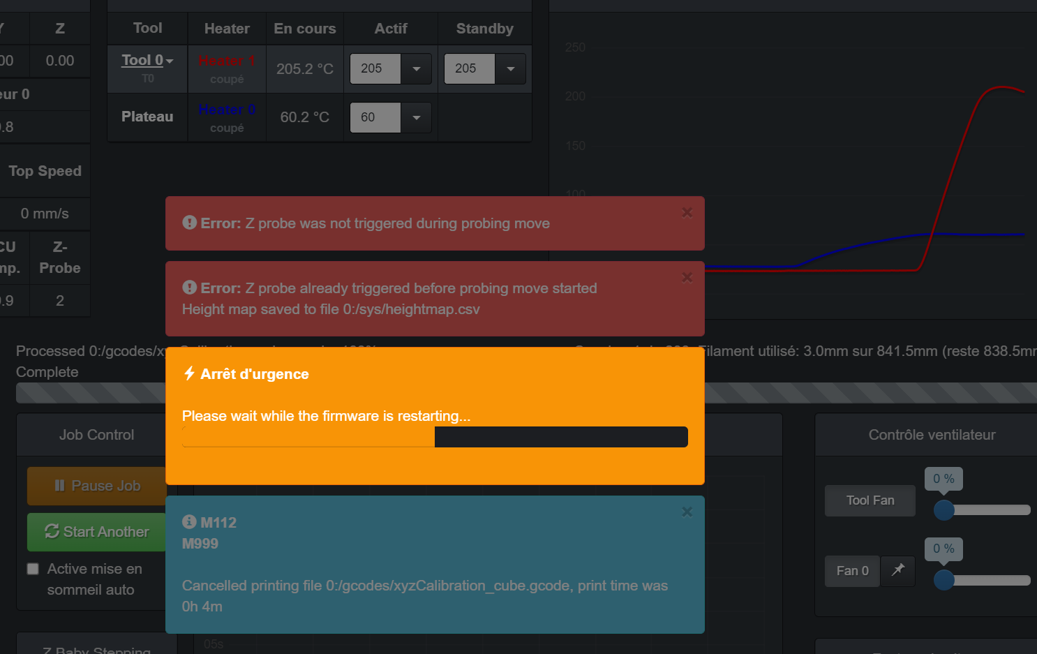
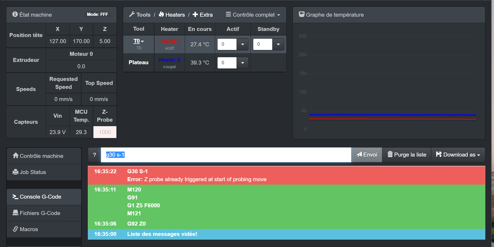 hello everyone, i have problems configuring my mini ir sensor can you help please
 -
@sgk if you post your config.g file, the chance for help is extremely higher

-
-
; ====================== Network ===========================M552 S1 ; enable network
M586 P0 S1 ; enable HTTP
M586 P1 S0 ; disable FTP
M586 P2 S0 ; disable TelnetM669 K1 ; select CoreXY mode
; ======================= Endstops =========================M574 X1 S1 P"xstop" ; configure active-high endstop for low end on X via pin xstop
M574 Y2 S1 P"ystop" ; configure active-high endstop for high end on Y via pin ystop
M574 Z1 S2 ; configure Z-probe endstop for low end on ZM575 P1 S1 B57600 ; Set things up for the PanelDue
; Filament sensor;M591 D0 P1 C"e0stop" S1 ; Set Filament sensor Simple type (High) for extruder drive 0, connected to endstop input 3 (E0
; ======================= Drives ===========================M569 P0 S0 ; Drive 0 goes backwards blv: its was S1
M569 P1 S0 ; Drive 1 goes backwards blv: its was S1
M569 P2 S0 ; Drive 2 goes forwards
M569 P3 S1 ; Drive 3 goes backwards WAS 0
M569 P4 S0 ; Drive 4 goes forwards
M584 X0 Y1 Z2:4 E3 ; set drive mapping; ===================== Drive Settings =====================M350 X16 Y16 Z16 E16 I1 ; Configure microstepping with interpolation
M92 X200,120 Y200,541 Z800 E714.36 ; Set steps per mm for orbiter
M566 X600 Y600 Z800 E600 ; Set maximum instantaneous speed changes (Jerk) (mm/min)
M203 X20000 Y20000 Z600 E7200 ; Set maximum speeds (mm/min)
M201 X1000 Y1000 Z100 E700 ; Set accelerations (mm/s^2)
M906 X1000 Y1000 Z1000 E1200 I10 ; Set motor currents (mA) and motor idle factor in per cent
M84 S30 ; Set idle timeout; ===================== Axis Limits ========================M208 X-23 Y0 Z0 S1 ; Set axis minima
M208 X320 Y320 Z350 S0 ; Set axis maxima; ======================== Z-Probe =========================M558 P1 C"^zprobe.in" H5 F200 T9000 I0 R0.5 ; Set Z probe type mini ir sensor
G31 P500 X-2.24 Y-20.81 Z1.044 ; Set Z probe trigger value, offset and trigger height
M557 X20:270 Y20:270 S240 ; Define mesh grid; ======================== Heaters =========================M308 S0 P"bed_temp" Y"thermistor" T100000 B3950 ; define bed temperature sensor
M950 H0 C"bed_heat" T0 ; heater 0 uses the bed_heat pin, sensor 0
M307 H0 R0.345 C165.9 D7.58 S1.00 V23.6 ; Heatbed PID
M140 H0 ; map heated bed to heater 0
M143 H0 S120 ; set temperature limit for heater 0 to 120C
M308 S1 P"e0temp" Y"thermistor" T100000 B3950 ; define E0 temperature sensor
M950 H1 C"e0heat" T1 ; heater 1 uses the e0heat pin and sensor 1
M307 H1 R2.697 C168.9:154.1 D9.06 S1.00 V23.6 ; Hotend PID .4mm
M143 H1 S260 ; set temperature limit for heater 0 to 260C
M308 S2 P"mcu-temp" Y"mcu-temp" A"Duet Board" ; Configure MCU sensor; ======================== Tools ===========================M563 P0 S"T0" D0 H1 F1 ; Define tool 0
G10 P0 X0 Y0 Z0 ; Set tool 0 axis offsets
G10 P0 R0 S0 ; Set initial tool 0 active and standby temperatures to 0C; ========================= Fans ===========================M950 F1 C"fan1" Q500 ; create fan 1 on pin fan1 and set its frequency
M106 P1 C"HE Fan" S1 H1 T45 ; set fan 1 value. Thermostatic control is turned on 100% at 45deg;Tool Fan/ Layer Fan
M950 F0 C"fan0" Q500 ; create fan 0 on pin fan0 and set its frequency
M106 P0 S1 H-1 ; set fan 0 value. Thermostatic control is turned off;MB cooling fan layer
M950 F2 C"fan2" Q500 ; create fan 2 on pin fan2 and set its frequency
M106 P2 C"MB Fan" S1 H2 T35:55 ; set fan 2 value. Thermostatic control is turned on Temp Range of 35 - 55 deg; ===================== Custom settings ====================M572 D0 S0.275 ; Set bowden extruder elasticity compensation for E0
;M207 S4.0 F2400 Z2.275 ; Set firmware retraction parameters
M207 S4.0 F2400 Z0.075 ; Set firmware retraction parameters
M564 H0 ; Let the Jog buttons work blv: added to allow jog buttons; Scanner support (debug);M750
; Set up DHT sensor on channels 101-102;M305 P101 X405 S"DHT temperature" T11
;M305 P102 X455 S"DHT humidity [%]" T11; Automatic power savingM911 S21 R22 P"M913 X0 Y0 G91 M83 G1 Z3 E-5 F1000" ; Set voltage thresholds and actions to run on power loss
; ====================== Miscellaneous =====================M501 ; load saved parameters from non-volatile memory
M500 ; save
T0 ; select first toolM575 P1 S1 B57600 ; enable support for PanelDue
;M911 S10 R11 P"M913 X0 Y0 G91 M83 G1 Z3 E-5 F1000" ; set voltage thresholds and actions to run on power loss -
@sgk
                 ; ===================== Drive Settings =====================


M350 X16 Y16 Z16 E16 I1                            ; Configure microstepping with interpolation
M92 X200,120 Y200,541 Z800 E714.36                 ; Set steps per mm for orbiter
Replace the comas with a dot after that go to the console and enter g98 P"config.g" and post the result.
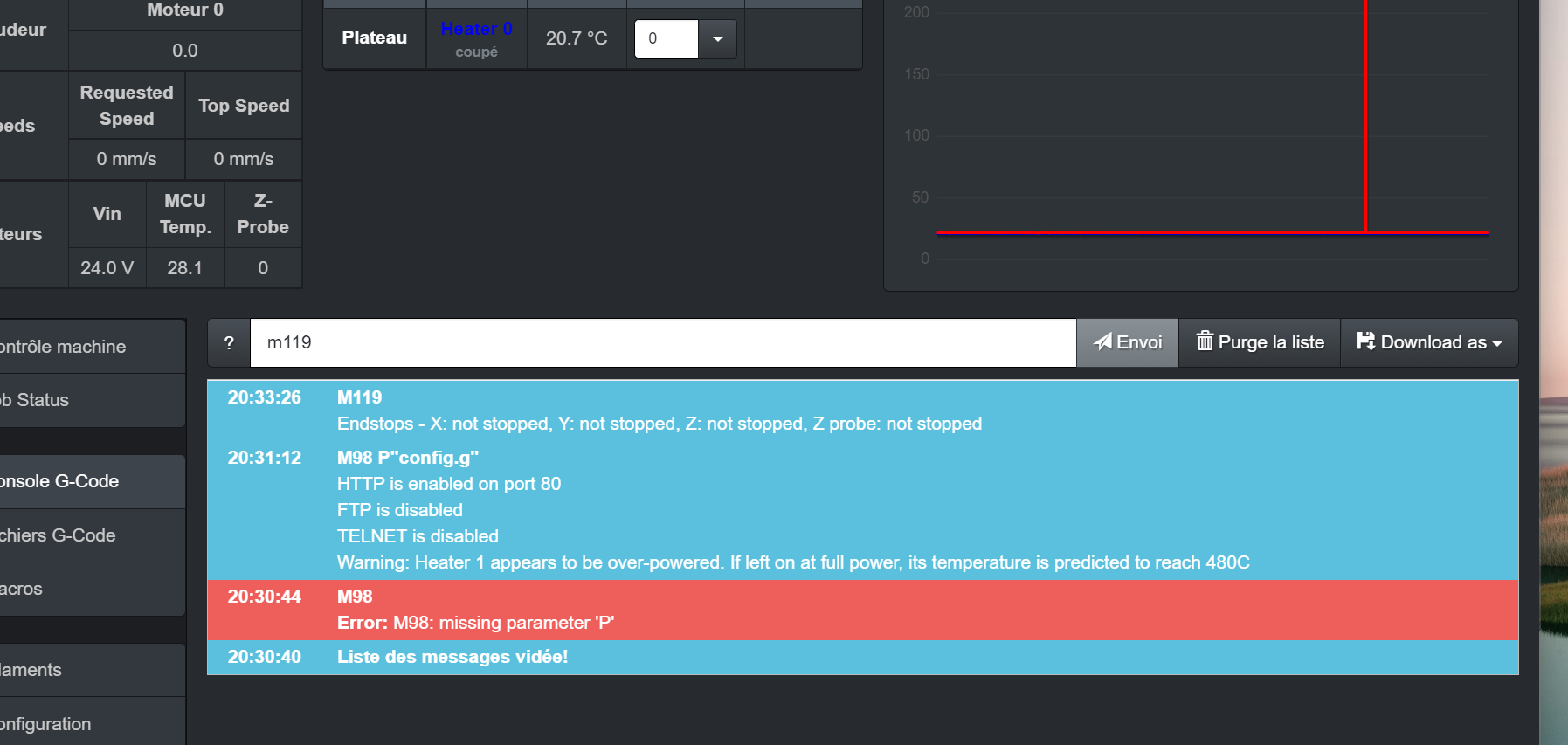
When you now enter M119 in the console look if the Z probe is triggered if it so change the following lineM558 P1 C"^zprobe.in" H5 F200 T9000 I0 R0.5 ; Set Z probe type mini ir sensorto
M558 P1 C"!^zprobe.in" H5 F200 T9000 I0 R0.5 ; Set Z probe type mini ir sensoran retest with M119
-
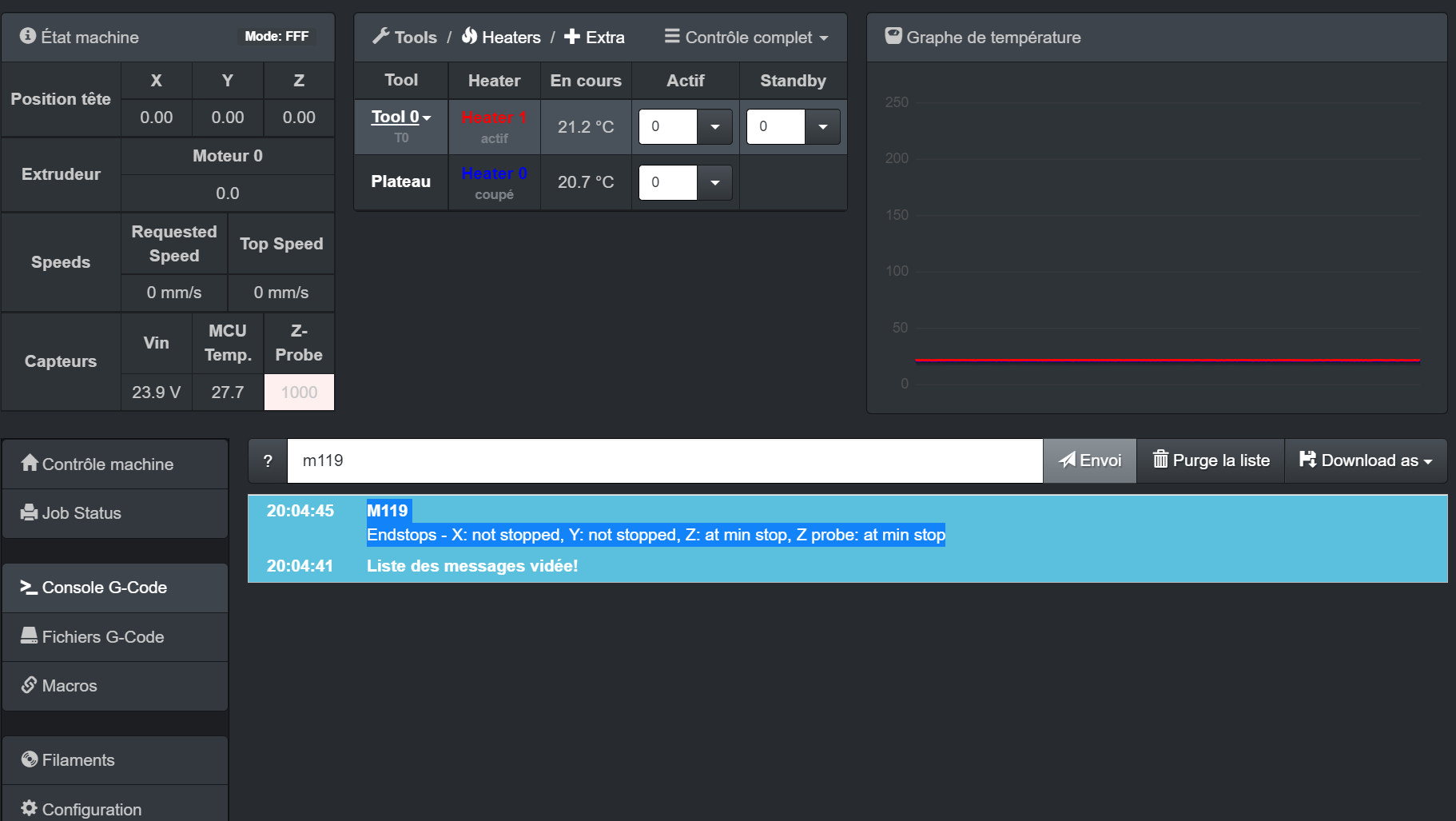
@siam i have M119
Endstops - X: not stopped, Y: not stopped, Z: at min stop, Z probe: at min stop -
-
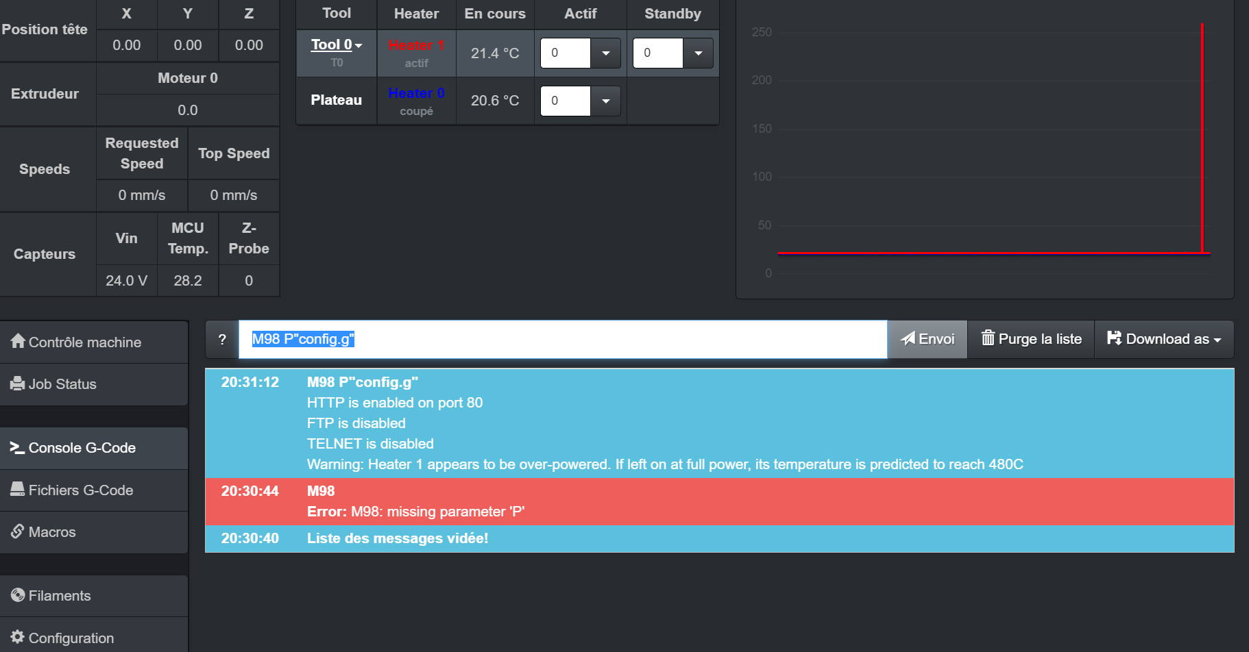
@sgk have you made the changes which I have provided in my last post? And can you post the result of M98 P"config.g"
-
-
M558 P1 C"!^zprobe.in" H5 F200 T9000 I0 R0.5 ; Set Z probe type mini ir sensor
-
-
when I do Calibrate the Z probe trigger height the bed crashed into the nozzle when I hit g30 s-1
-
@sgk trigger height needs to be a positive value for the IR probe in RepRapFirmware.
-
thank you for answering me.
when i type g30 s-1 the bed doesn't stop -
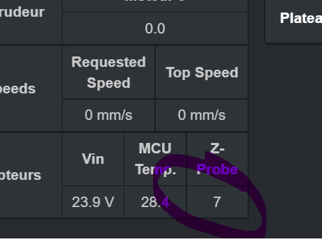
is normal -
@sgk if you have the gantry high enough do that you can trigger the probe by putting your finger under it, can you see that the z probe value on DWC goes up?
Also, what kind of bed material do you use?
-

-
@sgk this bed
-
@sgk pei sheet is semi transparent and I've had mixed success with the IR board on it. I take it you also tested it with the paper underneath?
-
@oliof yes yes but the bed does not stop