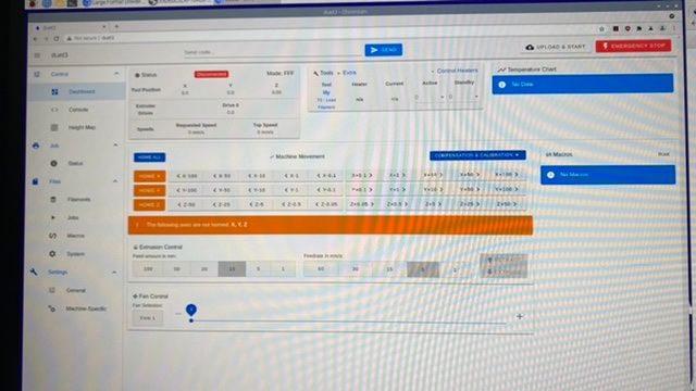
Large Format Dowell to Duet conversion
-
Just for the record
	Edit the M307 H1 command in config.g to match this. Omit the V parameter if the heater is not powered from VIN.
03/11/2021, 13:42:50	Auto tuning heater 1 completed after 3 idle and 30 tuning cycles in 1842 seconds. This heater needs the following M307 command:
 M307 H1 B0 R1.465 C296.7:296.7 D8.30 S1.00 V24.0
03/11/2021, 13:42:49	Warning: Turning on the print cooling fan did not increase hot end cooling. Check that the correct fan has been configured.
03/11/2021, 13:38:35	Auto tune starting phase 5, tuning with fan on
03/11/2021, 13:38:34	Warning: heater behaviour was not consistent during tuning
03/11/2021, 13:18:05	Auto tune starting phase 4, tuning with fan off
03/11/2021, 13:14:58	Auto tune starting phase 3, heating system settling
03/11/2021, 13:12:11	Auto tune starting phase 2, heating up
03/11/2021, 13:12:07	M303 T0 S200
Auto tuning heater 1 using target temperature 200.0°C and PWM 1.00 - do not leave printer unattended
I have now wired the two fans either side of the pellet loading chamber in parallelp to out8 on the 6HC. I can't here it idling however. Maybe I should swap polarity.
Is it possible to wire the 3D touch to the 3HC as the wires can't reach the 6HC where it is?
For reference:
Configuration file for Duet 3 (firmware version 3.3) ; executed by the firmware on start-up ; ; generated by RepRapFirmware Configuration Tool v3.3.3 on Fri Oct 01 2021 16:59:54 GMT+0100 (British Summer Time) ; General preferences G90 ; send absolute coordinates... M83 ; ...but relative extruder moves ; Wait a moment for the CAN expansion boards to start G4 S2 ; Drives M569 P0.0 S1 ; physical drive 0.0 goes forwards M569 P0.1 S1 ; physical drive 0.1 goes forwards M569 P0.2 S0 ; physical drive 0.2 goes forwards M569 P0.3 S0 ; physical drive 0.3 goes forwards M569 P0.4 S0 ; physical drive 0.4 goes forwards M569 P0.5 S0 ; physical drive 0.5 goes forwards M569 P1.0 S1 ; physical drive 1.0 goes forwards M584 X0.0 Y0.1 Z0.2:0.4:0.5:0.3 E1.0 M350 X16 Y128 Z16 E16 I1 ; configure microstepping with interpolation M92 X80.00 Y1280.00 Z1926.00 E420.00 ; set steps per mm M566 X900.00 Y900.00 Z60.00 E120.00 ; set maximum instantaneous speed changes (mm/min) M203 X6000.00 Y6000.00 Z500.00 E1200.00 ; set maximum speeds (mm/min) M201 X500.00 Y500.00 Z20.00 E250.00 ; set accelerations (mm/s^2) M906 X2800 Y2800 Z1200 E1200 I30 ; set motor currents (mA) and motor idle factor in per cent M84 S30 ; Set idle timeout ; Axis Limits M208 X0 Y0 Z0 S1 ; set axis minima M208 X1200 Y2000 Z1600 S0 ; set axis maxima ; Endstops M574 X1 S1 P"io1.in" ; configure active-high endstop for low end on X via pin io1.in M574 Y1 S1 P"io2.in" ; configure active-high endstop for low end on Y via pin io2.in M574 Z1 S1 P"io0.in" ; Z-Probe M558 P9 C"^1.io1.in" H100 F120 T6000 ; set Z probe type to switch and the dive height + speeds G31 P500 X0 Y0 Z2.5 ; set Z probe trigger value, offset and trigger height M556 S50 X0 Y0 Z0 ; set orthogonal axis compensation parameters M557 X15:215 Y15:195 S20 ; define mesh grid ; Heaters M308 S0 P"1.temp0" Y"PT1000" M950 H0 C"1.out0" T0 M307 H0 B1 R0.138 C790.6 D13.87 S1.00 V24.0 ; enable bang-bang mode for the bed heater and set PWM limit M140 H0 ; map heated bed to heater 0 M143 H0 S80 ; set temperature limit for heater 0 to 80C M308 S1 P"1.temp1" Y"thermistor" T100000 B3950 ; configure sensor 1 as thermistor on pin temp0 M950 H1 C"1.out1" T1 ; create nozzle heater output on out1 and map it to sensor 1 M307 H1 B0 R1.465 C296.7:296.7 D8.30 S1.00 V24.0 M307 H1 B0 S1.00 ; disable bang-bang mode for heater and set PWM limit M143 H1 S300 ; set temperature limit for heater 1 to 300C ; Fans M950 F0 C"out8" Q500 ; create fan 0 on pin out8 and set its frequency M106 P0 S0 H T45 ; set fan 0 value. Thermostatic control is turned on M950 F1 C"out9" Q500 ; create fan 1 on pin out9 and set its frequency M106 P1 S1 H-1 ; set fan 1 value. Thermostatic control is turned off ; Tools M563 P0 S"lily" D0 H1 F0:1 ; define tool 0 G10 P0 X100 Y100 Z0 ; set tool 0 axis offsets G10 P0 R0 S0 ; set initial tool 0 active and standby temperatures to 0C ; Custom settings are not defined -
@t3p3tony the fans are not working. Not sure why I’ve tried reversing the poles
-
@charles-fraser said in Large Format Dowell to Duet conversion:
M307 H1 B0 R1.465 C296.7:296.7 D8.30 S1.00 V24.0 03/11/2021, 13:42:49 Warning: Turning on the print cooling fan did not increase hot end cooling. Check that the correct fan has been configured.
You may need to re run the tuning after fixing the issues below.
M950 F0 C"out8" Q500                                            ; create fan 0 on pin out8 and set its frequency
M106 P0 S0 H T45
this is wrong. I assume the fans on out8 are to cool the pellet extruder itself (not the print) in the same manner as a hotend cooling fan that cools the cold side of a heatbreak on a filament hotend? In that case this should be:
M950 F0 C"out8" Q500                                            ; create fan 0 on pin out8 and set its frequency
M106 P0 H1 T45
This tells the Duet that when heater sensor 1 gets over 45C, turn on fan0. It wont be on until the hotend sensor goes over 45C
The print cooling fan is ok, assuming you have it plugged into out 9
M950 F1 C"out9" Q500                                            ; create fan 1 on pin out9 and set its frequency
M106 P1 S1 H-1                                                  ; set fan 1 value. Thermostatic control is turned off
however the fan associations for the tool are not right:
@charles-fraser said in Large Format Dowell to Duet conversion:
M563 P0 S"lily" D0 H1 F0:1
should be
M563 P0 S"lily" D0 H1 F1as the tool is associated with the print cooling fan (the otehr fan is alsready assoicated with the heater.
-
Okay the "heat-break" fans are working well now. The print cooling fan is not working even if I turn the 'TOOL FAN' slider up to 100 and switch polarity of the wires. Maybe it needs to actually be printing for that to come on?
okay next I am gonna keep rewiring this BL touch
-
Oh Quick question: Is it possible to do a PID tuning while extruding because this extruder pushes out so much material it will need a different heating tuning I recon to make it work best. Also which line is the steps per mm of extruded material please? The Extruder has a 20:1 gear NEMA17 that needs to spin jolly fast to get that screw moving around.
-
@t3p3tony PS: is there no way to wire the 3D touch to the 3HC? Cables just don’t reach the 6HC
-
@charles-fraser said in Large Format Dowell to Duet conversion:
and switch polarity of the wires
https://duet3d.dozuki.com/Wiki/Connecting_and_configuring_fans#Section_Caution
Caution
Fans are polarised. When connecting a fan to a fan connector, the positive wire (usually red) must be connected to the VFAN pin of that connector. The negative wire (normally black) must be connected to the FAN- pin if it is a controlled fan connector, or the GND pin if it is an always-on fan connector.
If you connect the fan the wrong way round, you may damage the fan, the Duet, or both.
Ian
-
I’m sorry it’s a bit of a fudge but I have only been able to get the 3D touch wired up (I hope correctly) with the 3HC, IO_2
Here is what the wiring from the touch is supposed to be:
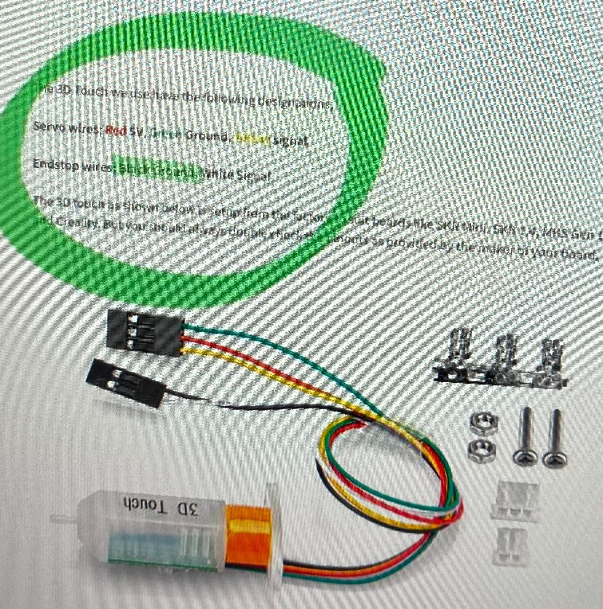
But the 3D touch I have does not have a white wire, it has a blue wire though so I am guessing that’s the only difference.
I have to connect the BL touch to two different cables, each with four wires in them to reach the board at the other end of the printer. In one of the cables, two of the wires are already used by the NTC thermistor so it looks like this:
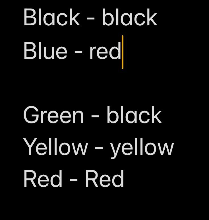
Then I can only reach IO_2 on the 3H with all that following this diagram:
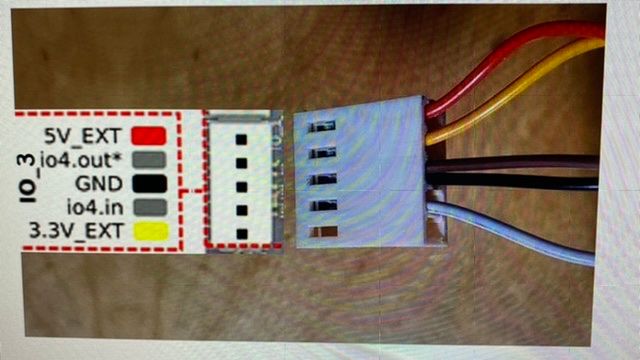
Which looks like this:
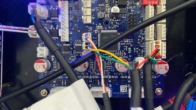
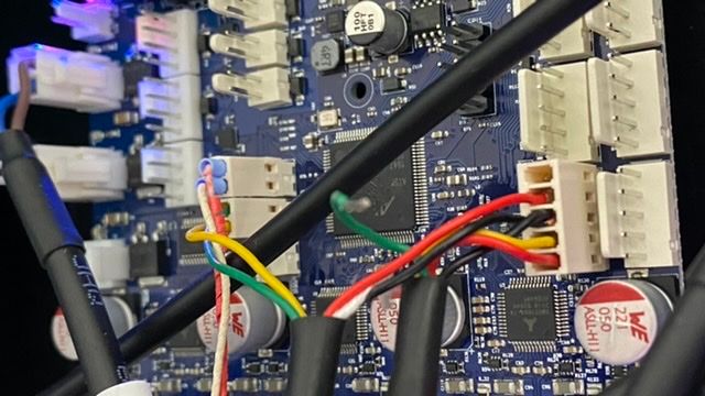
I hope that’s correct! I’ll try to change the code and hope it works!
-
WOAH! All I did was change the IO_1 to IO_2 in the config file and now so many errors and the heaters missing and things:
Configuration file for Duet 3 (firmware version 3.3)
; executed by the firmware on start-up
;
; generated by RepRapFirmware Configuration Tool v3.3.3 on Fri Oct 01 2021 16:59:54 GMT+0100 (British Summer Time)

; General preferences
G90                                                             ; send absolute coordinates...
M83                                                             ; ...but relative extruder moves

; Wait a moment for the CAN expansion boards to start
G4 S2


; Drives
M569 P0.0 S1                                                    ; physical drive 0.0 goes forwards
M569 P0.1 S1                                                    ; physical drive 0.1 goes forwards
M569 P0.2 S0                                                    ; physical drive 0.2 goes forwards
M569 P0.3 S0                                                    ; physical drive 0.3 goes forwards
M569 P0.4 S0                                                    ; physical drive 0.4 goes forwards
M569 P0.5 S0                                                    ; physical drive 0.5 goes forwards
M569 P1.0 S1                                                    ; physical drive 1.0 goes forwards
M584 X0.0 Y0.1 Z0.2:0.4:0.5:0.3 E1.0
M350 X16 Y128 Z16 E16  I1                                ; configure microstepping with interpolation
M92 X80.00 Y1280.00 Z1926.00 E420.00          ; set steps per mm
M566 X900.00 Y900.00 Z60.00 E120.00        ; set maximum instantaneous speed changes (mm/min)
M203 X6000.00 Y6000.00 Z500.00 E1200.00 ; set maximum speeds (mm/min)
M201 X500.00 Y500.00 Z20.00 E250.00        ; set accelerations (mm/s^2)
M906 X2800 Y2800 Z1200 E1200 I30                      ; set motor currents (mA) and motor idle factor in per cent
M84 S30                                                         ; Set idle timeout

; Axis Limits
M208 X0 Y0 Z0 S1                                                ; set axis minima
M208 X1200 Y2000 Z1600 S0                                       ; set axis maxima

; Endstops
M574 X1 S1 P"io1.in"                                            ; configure active-high endstop for low end on X via pin io1.in
M574 Y1 S1 P"io2.in"                                            ; configure active-high endstop for low end on Y via pin io2.in
M574 Z1 S1 P"io0.in"

; Z-Probe
M558 P9 C"^1.io2.in" H100 F120 T6000                            ; set Z probe type to switch and the dive height + speeds
G31 P500 X0 Y0 Z2.5                                             ; set Z probe trigger value, offset and trigger height
M556 S50 X0 Y0 Z0                                               ; set orthogonal axis compensation parameters
M557 X15:215 Y15:195 S20                                        ; define mesh grid

; Heaters
M308 S0 P"1.temp0" Y"PT1000"
M950 H0 C"1.out0" T0
M307 H0 B1 R0.138 C790.6 D13.87 S1.00 V24.0                   ; enable bang-bang mode for the bed heater and set PWM limit
M140 H0                                                         ; map heated bed to heater 0
M143 H0 S80                                                    ; set temperature limit for heater 0 to 80C
M308 S1 P"1.temp1" Y"thermistor" T100000 B3950                                    ; configure sensor 1 as thermistor on pin temp0
M950 H1 C"1.out1" T1                                              ; create nozzle heater output on out1 and map it to sensor 1
M307 H1 B0 R1.465 C296.7:296.7 D8.30 S1.00 V24.0
M307 H1 B0 S1.00                                                ; disable bang-bang mode for heater  and set PWM limit
M143 H1 S300                                                    ; set temperature limit for heater 1 to 300C

; Fans
M950 F0 C"out8" Q500                                            ; create fan 0 on pin out8 and set its frequency
M106 P0 H1 T45                                             ; set fan 0 value. Thermostatic control is turned on
M950 F1 C"out9" Q500                                            ; create fan 1 on pin out9 and set its frequency
M106 P1 S1 H-1                                                  ; set fan 1 value. Thermostatic control is turned off

; Tools
M563 P0 S"lily" D0 H1 F1
G10 P0 X100 Y100 Z0                                             ; set tool 0 axis offsets
G10 P0 R0 S0                                                    ; set initial tool 0 active and standby temperatures to 0C

; Custom settings are not defined
03/11/2021, 17:00:56 Error: M143: Heater 1 does not exist 03/11/2021, 17:00:56 Error: M307: Heater 1 not found 03/11/2021, 17:00:56 Error: M307: Heater 1 not found 03/11/2021, 17:00:56 Error: M950: Response timeout: CAN addr 1, req type 6026, RID=12 03/11/2021, 17:00:53 Error: M308: Response timeout: CAN addr 1, req type 6031, RID=10 03/11/2021, 17:00:51 Error: M307: Heater 0 not found 03/11/2021, 17:00:51 Error: M143: Heater 0 does not exist 03/11/2021, 17:00:51 Error: M950: Response timeout: CAN addr 1, req type 6026, RID=8 03/11/2021, 17:00:50 Error: M308: Response timeout: CAN addr 1, req type 6031, RID=6 03/11/2021, 17:00:47 Error: G31: Invalid Z probe index 03/11/2021, 17:00:47 Error: M558: Response timeout: CAN addr 1, req type 6036, RID=5 03/11/2021, 17:00:46 Error: Invalid remote handle 03/11/2021, 17:00:46 Error: M906: Response timeout: CAN addr 1, req type 6043, RID=4 03/11/2021, 17:00:45 Error: M92: Response timeout: CAN addr 1, req type 6042, RID=3 03/11/2021, 17:00:45 Error: M350: Response timeout: CAN addr 1, req type 6042, RID=2 03/11/2021, 17:00:45 Error: M584: Response timeout: CAN addr 1, req type 6042, RID=1 03/11/2021, 17:00:44 Error: M569: Response timeout: CAN addr 1, req type 6018, RID=0 03/11/2021, 17:00:39 Connection established 03/11/2021, 17:00:32 Connection interrupted, attempting to reconnect... 03/11/2021, 17:00:30 Emergency stop, attemping to reconnect... 03/11/2021, 16:58:33 Error: M307: Heater 1 not found 03/11/2021, 16:58:33 Error: M143: Heater 1 does not exist 03/11/2021, 16:58:33 Error: M307: Heater 1 not found 03/11/2021, 16:58:33 Error: M950: Response timeout: CAN addr 1, req type 6026, RID=12 03/11/2021, 16:58:30 Error: M308: Response timeout: CAN addr 1, req type 6031, RID=10 03/11/2021, 16:58:28 Error: M143: Heater 0 does not exist 03/11/2021, 16:58:28 Error: M307: Heater 0 not found 03/11/2021, 16:58:28 Error: M950: Response timeout: CAN addr 1, req type 6026, RID=8 03/11/2021, 16:58:26 Error: M308: Response timeout: CAN addr 1, req type 6031, RID=6 03/11/2021, 16:58:24 Error: G31: Invalid Z probe index 03/11/2021, 16:58:24 Error: M558: Response timeout: CAN addr 1, req type 6036, RID=5 03/11/2021, 16:58:23 Error: Invalid remote handle 03/11/2021, 16:58:23 Error: M906: Response timeout: CAN addr 1, req type 6043, RID=4 03/11/2021, 16:58:21 Error: M92: Response timeout: CAN addr 1, req type 6042, RID=3 03/11/2021, 16:58:20 Error: M350: Response timeout: CAN addr 1, req type 6042, RID=2 03/11/2021, 16:58:19 Error: M584: Response timeout: CAN addr 1, req type 6042, RID=1 03/11/2021, 16:58:18 Error: M569: Response timeout: CAN addr 1, req type 6018, RID=0 03/11/2021, 16:58:16 Connection established -
The 3HC is not being seen any more. It no longer flashes the amber light in time with the 6HC
When I send M115 B1 it just spins forever
-
-
@charles-fraser said in Large Format Dowell to Duet conversion:
The print cooling fan is not working even if I turn the 'TOOL FAN' slider up to 100 and switch polarity of the wires. Maybe it needs to actually be printing for that to come on?
no it does not need to be printing. try connecting the fan directly to +24V and ground to test it works (assuming its a 24V fan).
@charles-fraser said in Large Format Dowell to Duet conversion:
Is it possible to do a PID tuning while extruding because this extruder pushes out so much material it will need a different heating tuning I recon to make it work best.
no - but we do plan to add extrusion look ahead in future versions of the firmware.
@charles-fraser said in Large Format Dowell to Duet conversion:
Also which line is the steps per mm of extruded material please? The Extruder has a 20:1 gear NEMA17 that needs to spin jolly fast to get that screw moving around.
the E value in this:
M92 X80.00 Y1280.00 Z1926.00 E420.00 ; set steps per mm@charles-fraser said in Large Format Dowell to Duet conversion:
PS: is there no way to wire the 3D touch to the 3HC? Cables just don’t reach the 6HC
you should connect it to the same board as the Z motors are on for now:
https://duet3d.dozuki.com/Wiki/Duet_3_firmware_configuration_limitationsDue to CAN latency the motors connected to expansion boards may slightly overshoot the position at which the endstop or Z probe was triggered. This would not usually matter for an endstop switch, but it does mean that if the Z motor(s) is/are connected to an expansion board then repeated probing with a Z probe (e.g. for mesh bed compensation) is not advisable. This will be fixed in a future release
@charles-fraser said in Large Format Dowell to Duet conversion:
I removed the 3D touch. Still Only the lily hotend shows now. No bed, no temps
when you lose communication with the 3HC then you will lose communication with everything on that board.
Try undoing the changes you made to config.g and then reset everything (without the 3d touch installed). Unless that damaged the board it should all come back up.
-
I undid the changes and unplugged the 3D touch and it still does not work. How can even wiring up one io wrong fry the whole board?
I noticed, before all this crashed, the print cooling fan was spinning but hardly getting going then stopping again.
-
@charles-fraser said in Large Format Dowell to Duet conversion:
I noticed, before all this crashed, the print cooling fan was spinning but hardly getting going then stopping again
unplug this as well - the power cycle the power to both the 6HC and the 3HC. Run M98 P"0:sys/config.g" to verify the changes are undone.
-
Nothing is happening when I do any commands anymore. It just spins around and around. All things added are disconnected now. The 3HC doesnt blink anymore

-
@charles-fraser can you still access the network interface? in that case send M122
-
m122 === Diagnostics === RepRapFirmware for Duet 3 MB6HC version 3.4.0beta5 (2021-10-12 13:53:56) running on Duet 3 MB6HC v1.01 or later (SBC mode) Board ID: 08DJM-9P63L-DJ3S0-7J1D6-3SD6S-1UJV8 Used output buffers: 1 of 40 (12 max) === RTOS === Static ram: 151104 Dynamic ram: 65108 of which 0 recycled Never used RAM 134460, free system stack 219 words Tasks: SBC(ready,0.4%,518) HEAT(notifyWait,0.1%,361) Move(notifyWait,0.0%,351) CanReceiv(notifyWait,0.0%,944) CanSender(notifyWait,0.0%,374) CanClock(delaying,0.0%,333) TMC(notifyWait,7.1%,92) MAIN(running,41.2%,1241) IDLE(ready,51.2%,30), total 100.0% Owned mutexes: HTTP(MAIN) === Platform === Last reset 00:00:30 ago, cause: power up Last software reset details not available Error status: 0x00 Step timer max interval 132 MCU temperature: min 12.4, current 21.8, max 21.8 Supply voltage: min 24.1, current 24.2, max 24.2, under voltage events: 0, over voltage events: 0, power good: yes 12V rail voltage: min 12.1, current 12.2, max 12.2, under voltage events: 0 Heap OK, handles allocated/used 0/0, heap memory allocated/used/recyclable 0/0/0, gc cycles 0 Driver 0: pos 0, standstill, SG min/max 0/0, reads 41983, writes 14 timeouts 0 Driver 1: pos 0, standstill, SG min/max 0/0, reads 41983, writes 14 timeouts 0 Driver 2: pos 0, standstill, SG min/max 0/0, reads 41983, writes 14 timeouts 0 Driver 3: pos 0, standstill, SG min/max 0/0, reads 41983, writes 14 timeouts 0 Driver 4: pos 0, standstill, SG min/max 0/0, reads 41983, writes 14 timeouts 0 Driver 5: pos 0, standstill, SG min/max 0/0, reads 41983, writes 14 timeouts 0 Date/time: 2021-11-03 20:39:44 Slowest loop: 0.97ms; fastest: 0.05ms === Storage === Free file entries: 10 SD card 0 not detected, interface speed: 37.5MBytes/sec SD card longest read time 0.0ms, write time 0.0ms, max retries 0 === Move === DMs created 125, segments created 0, maxWait 0ms, bed compensation in use: none, comp offset 0.000 === MainDDARing === Scheduled moves 0, completed 0, hiccups 0, stepErrors 0, LaErrors 0, Underruns [0, 0, 0], CDDA state -1 === AuxDDARing === Scheduled moves 0, completed 0, hiccups 0, stepErrors 0, LaErrors 0, Underruns [0, 0, 0], CDDA state -1 === Heat === Bed heaters = 0 -1 -1 -1 -1 -1 -1 -1 -1 -1 -1 -1, chamberHeaters = -1 -1 -1 -1 === GCodes === Segments left: 0 Movement lock held by null HTTP* is doing "M122" in state(s) 0 Telnet is idle in state(s) 0 File is idle in state(s) 0 USB is idle in state(s) 0 Aux is idle in state(s) 0 Trigger* is idle in state(s) 0 Queue is idle in state(s) 0 LCD is idle in state(s) 0 SBC is idle in state(s) 0 Daemon is idle in state(s) 0 Aux2 is idle in state(s) 0 Autopause is idle in state(s) 0 Code queue is empty === CAN === Messages queued 168, received 0, lost 0, longest wait 0ms for reply type 0, peak Tx sync delay 0, free buffers 49 (min 48), ts 154/0/0 Tx timeouts 0,0,153,13,0,0 last cancelled message type 30 dest 127 === SBC interface === State: 4, failed transfers: 0, checksum errors: 649 Last transfer: 2ms ago RX/TX seq numbers: 16350/750 SPI underruns 2, overruns 2 Disconnects: 0, timeouts: 0, IAP RAM available 0x2b7dc Buffer RX/TX: 0/0-0 === Duet Control Server === Duet Control Server v3.4-b5 Code buffer space: 4096 Configured SPI speed: 8000000Hz Full transfers per second: 37.18, max wait times: 2187.4ms/29.1ms Codes per second: 0.01 Maximum length of RX/TX data transfers: 2868/560 -
@charles-fraser and after doing the following:
Power cycle the 3HC
send M98 P"0:sys/config.g"
Send M122 B1 -
I’ve done that and nothing. When I send those commands the DWC gets stuck in the spinning wheel of death. There is no blinking light on the 3HC
-
@charles-fraser it sounds like that 3d touch has caused an issues (or resurfaced an issue from the previous heater problems) with the 3HC. I remember you had issues with it right at the beginning - is this a new 3d touch or your original one?
We previously reset and reflashed the firmware on the 3HC. I think that's the step to take again now:
To force a firmware reload on the 3HC set all the dip switched to 0, power cycle the 3HC, you should see the diag light flash a bit. when its showing steady flashing in sync with the mainboard, switch the dip switch back to 1 as it was then power cycle the 3HC.
