Connecting RGBW 24V LED strip to Duet 2 WIFi board
-
Hello I am new to the duet board and am having trouble connecting a 24v LED Strip to my duet 2 wifi board. I found a video on youtube where he powers the LEDs from the PSU and then connects the RGBW wires to different heaters on the duet expansion board.
Video : https://www.youtube.com/watch?v=RNxyfYwVHN4
I am trying to do the same thing but using the expansion heaters pin. I power the LEDs with the 24v psu, connect the red LEDs to heater4, green to heater5, blue to heater6, and white to heater7. In my Config.g file I added the following code at the end:
; Lights
M950 P13 C"exp.heater4" Q500 ; Assigns red to P13
M950 P18 C"exp.heater5" Q500 ; Assigns green to P18
M950 P23 C"exp.heater6" Q500 ; Assigns blue to P23
M950 P31 C"exp.heater7" Q500 ; Assigns white to P31
M42 P13 S0 ; Turn red LED on
M42 P18 S0 ; Turn green LED off
M42 P23 S0 ; Turn blue LED off
M42 P31 S0 ; Turn white LED offWhen I turn on the board the LEDs light up white but my boards wifi disconnects, my Extruder fan (Fan1) turns on and the diag LED lights up. I disconnect the LEDs and reset the board but the same thing keeps happening. This is my second attempt at connecting the LEDs strip, during my first attempt I tried powering the LEDs through the PWM fan2 but the same thing happened. I was able to get my board working again by erasing the firmware and reinstalling it.
Can someone please explain to me what I am doing wrong and what I can do to be able to get the LEDs to work and be programable through the congif.g file.
-
@csosa which Firmware Version are you running?
Best
-
@pcr
Firmware Version 3.3 -
@csosa Does the LED strip have any driver chips or a controller onboard? If not, you need some small FET drivers ( 1 Amp should do) between RGB-pins and expansion header. I have good experience with a 2$ quad driver board TB6612. (was 1$ before supply shortage)
-
@o_lampe
Thanks for the advice. The LEDs do not have a driver chips or a controller onboard. Could you please send me a link to the FET driver you recommended, cant seem to find it on Amazon. Would I need a divers for each color, RGBW? -
-
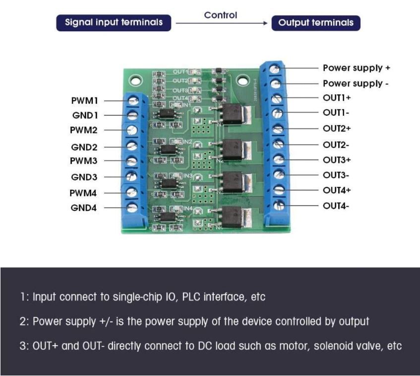
Thank you for your help. I have never used a driver before so I am not sure how to wire it to the Duet and LEDs. The driver I got has the following pin descriptions:
AIN1/AIN2: Control Signal input terminal
BIN1/BIN2: Control Signal input terminal
PWMA/PWMB: Control Signal input terminal
A01/A02: Motor control output
B01/B02: Motor control output
STBY: normal working/standby state control pin
VM: motor drive voltage
VCC: logic level input terminal
GND: groundWould the following wiring connections be correct?
Left side of driver
Empty----------->PWMA
Heater pin 4-->AIN2
Heater pin 5-->AIN1
Empty----------->STBY
Heater pin 6-->BIN1
Heater pin 7-->BIN2
Empty----------->PWMB
Empty----------->GNDRight Side of driver
VM<-------- PSU 24v+
VCC<------- LED 24V
GND<------ PSU GND
A01<--------LED R
A02<--------LED G
B02<--------LED B
B01<--------LED W
GND<-------EmptyThanks again for all your help.
-
@csosa I must apologize, the fact you are using a 24V LED strip slipped my brain. The driver I proposed is good for only 12V

If you still can use it, you'd have to add at least one GND signal from Duet to driver if they don't use the same powersupply -
@o_lampe
According to the datasheet the TB6612FNG driver can handle an Input voltage between 2.7 V – 10.8 V. Could I instead use something like the Hilitand MOS FET PWM 3-20V to 3.7-27VDC 10A 4-Channel Driver Module PLC Amplifier Circuit Board ? -
@csosa Yes, this one looks better suited.
-
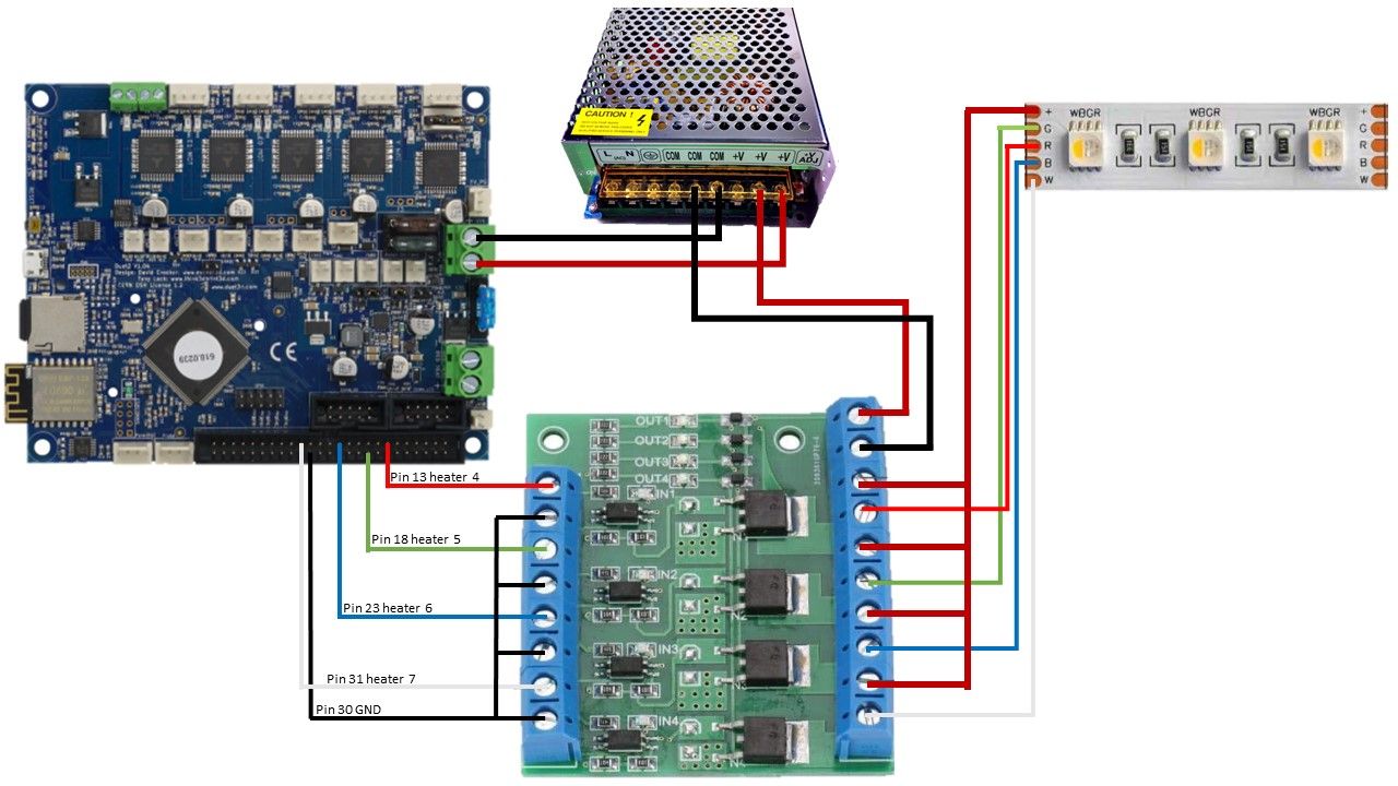
Great! So based on the inputs/outputs of the driver would the wiring diagram below be the correct?
-
So the board arrived and I wired it just like in the image from my last post but the LEDs still don't work. I checked the voltage from each of the heater pins and they are all different.
Heater pin 4 -> 2.29v
Heater pin 5 -> 3.25v
Heater pin 6 -> 0.13v
Heater pin 7 -> 0.23vTo check if the board was working right I checked the voltage from pin 43 which is suppose to be 3.3v and it is working just fine.
Next I tried turning on and off the pin using the M42 P# S1 or M42 P# S0 and nothing happens, all the voltages stay the same.
I am at a lost and have no idea what I am doing wrong. Below is the section of my config.g code that controls the lights. I tried changing the Q value of the M950 command but that doesn't change anything.
; Lights
M950 P5 C"exp.heater4" Q250 ; Assigns red to Pin 13
M950 P6 C"exp.heater5" Q250 ; Assigns green to Pin 18
M950 P7 C"exp.heater6" Q250 ; Assigns blue to Pin 23
M950 P8 C"exp.heater7" Q250 ; Assigns white to Pin 31
M42 P5 S0 ; Turn red LED off
M42 P6 S0 ; Turn green LED off
M42 P7 S0 ; Turn blue LED off
M42 P8 S0 ; Turn blue LED off -
@csosa said in Connecting RGBW 24V LED strip to Duet 2 WIFi board:
; Lights
M950 P5 C"exp.heater4" Q250 ; Assigns red to Pin 13You can try and activate the internal pullup for the heater pins with '^' :
M950 P5 C"^exp.heater4" Q250 -
I tried added '^' to all four heater pins and nothing changed.
I decided to test my board by enabling the pull up resistor '^' and inverting the input '!' to see how it affects the voltage. The results I got are shown below, as you can see the voltages are all over the place.
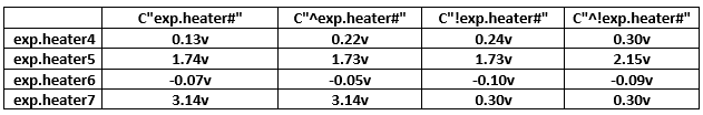
I also tried added MT3608 DC boosters to the pins in hope that that might boost the voltage to 3.3v but every time I connect it, the voltage coming from the pins just drops.
-
@csosa
That's confusing...are you sure about the GND pin you measured voltages against? Try using #pin2 from the expansion header.
Did you try to run M98 P"config.g" to see if any errors pop up?Maybe there's an issue with using a heater output without defining a temp-sensor?
Anyone who can chime in here? -
@o_lampe said in Connecting RGBW 24V LED strip to Duet 2 WIFi board:
Maybe there's an issue with using a heater output without defining a temp-sensor?
Something like
M950 H4 C"nil" ; undefine heater4 pin M950 P4 C"exp.heater4" Q250 -
I ran the M98 P"config.g" and got back the following
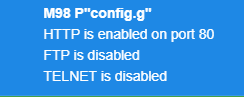
I am not sure is FTP and TELNET are suppose to be enabled but other than that it doesn't look like there are any errors in config.g
I also switched the GND to pin 2 (which is normally connected to my BL Touch). I checked the voltage from all four wires and got the following.
As you can see the voltage is all over the place expect for exp.heater7 which is working as it should. For heater pins 4 ,5 and 6 the voltage didn't change when I ran M42 P# S1.
While I was testing the last two wires (going to exp.heater6 and exp.heater7) my cooling fan started to turn on, the WIFI would disconnect and the diag. light would briefly flash. It did this a few time randomly so I unplugged all the wires going to the expansion pins. Now every time I turn it on it connects to WIFI but after a few minutes it disconnects and the diag. LED starts flashing.
Looks like I might have to erase the firmware and reinstall it before being able to test the "nil" function to undefine the heater pins.
-
@csosa
Maybe the fan went on, because you've used the same P# in a fan declaration?
I've tested all 5 heaters without "nil", mentioning that was just a last straw. In my case, they were real heaters, which can make a difference. -
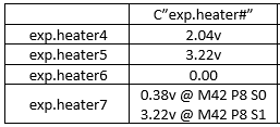
@csosa
From the Wiki:M42 switches a general purpose I/O pin. Use M42 Px Sy to set pin x to value y. The S field may be in the range 0..1 or 0..255.How does M42 know that S1 isn't meant as 1 of 255 ?
Answer: use S1.0 to tell it to switch on 100% -
Since my board kept disconnecting from the wifi and the diag light start flashing. I erased the firmware and tried reinstall it again using Fallback procedure #2. I am not sure why but the firmware doesn't seem to install on the board, the diag light wont turn off. I'm using Bossa to write and verify the firmware, but afterwards the diag light wont turn off. Usually I'm able to just erase the board and reinstall the firmware using Bossa and later YAT to setup the WIFI and make updates but this time it doesn't look like Bossa is installing anything. I also tried installing the firmware using SAM-BA version 2.17 but it wouldn't connect either.