Duet3D Logo Duet3D
    • Tags
    • Documentation
    • Order
    • Register
    • Login

    Dumbfounded ! Firmware bug in 3.4 beta 6?

    Scheduled Pinned Locked Moved Solved
    Beta Firmware
    5
    27
    1.3k
    Loading More Posts
    • Oldest to Newest
    • Newest to Oldest
    • Most Votes
    Reply
    • Reply as topic
    Log in to reply
    This topic has been deleted. Only users with topic management privileges can see it.
    • Phaedruxundefined
      Phaedrux Moderator
      last edited by

      I think you may be affected by this change in B6

      Upgrade notes:

      Important! After changing tool, RRF no longer moves the new tool head to the coordinates at which the old tool head was at when the Tn command was actioned. In most situations this should not matter, because GCode generators usually generate commands to move to the correct XYZ position after generating a Tn command. Usually, they restore XY before Z. However, Cura does it the other way round, which risks dragging the tool head across the print. Therefore when using Cura, or in any other situations in which you want to restore the old behaviour, we suggest you add command G1 R2 X0 Y0 Z2 Fxxx followed by G1 R2 Z0 Fxxx to the end of your tpost#.g files, if you don't already use those or similar commands.

      Z-Bot CoreXY Build | Thingiverse Profile

      GeneRisiundefined 1 Reply Last reply Reply Quote 0
      • GeneRisiundefined
        GeneRisi @Phaedrux
        last edited by GeneRisi

        @phaedrux OK !
        config.g

        ; Configuration file for Duet WiFi / Ethernet
        ; executed by the firmware on start-up
        
        ; *** General preferences ***
        ;
        M111 S0 						; Debugging off
        M550 P"ToolChanger" 			; Set machine name
        G21 							; Work in millimetres
        G90 							; Send absolute coordinates...
        M83 							; ...but relative extruder moves
        M555 P2 						; Set firmware compatibility to look like Marlin
        ;
        ; *** Network ***
        ;
        M552 S1							; Enable Networking
        M586 P0 S1 						; Enable HTTP
        M586 P1 S1 						; Enable FTP
        M586 P2 S0 						; Disable Telnet
        ;
        ; *** Kinematics ***
        ;
        M667 S1 					; Select CoreXY mode
        ;
        ; *** Endstops ***
        ;
        M574 X1 P"xstop" S1              					; Set X endstop as active high switch
        M574 Y1 P"ystop" S1                  				; Set Y endstop as active high switch
        M574 Z1 S2 											; Set Z endstop probe
        ;	note that M574 not used here for A or C 
        M915 C S5 F0 H200									; Coupler end stop is stall
        M915 A S10 F0 H200									; Wiper "A" end stop is stall
        
        M558 P8 C"zstop" X0 Y0 Z2 H3 F360:180 I0 T20000 	; Set Z probe type to switch, the axes for which it is used and the dive height + speeds
        G31 P200 X0 Y0 Z0	 								; Set Z probe trigger value, offset and trigger height
        ;
        ; *** Bed Leveling ***
        ;
        M557 X10:290 Y20:180 S40 			; Define mesh grid
        M376 H15							; bed compensation taper
        if !exists(global.freshMesh)
        	global freshMesh = false
        else
        	set global.freshMesh = false
        G29 Q2								; turn off bed mesh compensation (shouldn't be on, but ...)
        ;
        ; *** Drive direction ***
        ;
        M569 P0 S0 					; Drive 0 X
        M569 P1 S0 					; Drive 1 Y
        M569 P2 S1 					; Drive 2 Z
        M569 P3 S1 					; Drive 3 E0 - something strange here
        M569 P4 S1 					; Drive 4 E1
        M569 P5 S1 					; Drive 5 E2
        M569 P6 S1 					; Drive 6 E3
        M569 P7 S0 					; Drive 7 COUPLER
        M569 P8 S1 					; Drive 8 Wiper "A"
        M569 P9 S0 					; Drive 9 UNUSED
        ;
        ; *** Drive Mapping ***
        ;
        M584 X0 Y1 Z2 A8 C7 E3:4:5:6 		; Apply custom drive mapping
        ;
        ; *** AXES min and max ***
        ;
        M208 X-27:330 Y-49:243 Z0:300 A0:43 C0:500 S0 	; Set axis maxima & minima
        ;
        ; *** Stepping ***
        ;
        M92 X100 Y100 Z1600					; Set steps per mm at default 1/16 microstepping
        M350 X16 Y16 Z16 I1					; Configure microstepping with interpolation
        M350 E16:16:8:16 A16 C8 I1 			; Configure microstepping without interpolation except for Extruder 3
        M92 C100 A400 E655:655:417:409		; Set steps per mm at just defined microstepping
        ;
        ; *** Motion Settings ***
        ;
        M566 X400 Y400 Z8 A8 C2 E300:300:300:300					; Set maximum instantaneous speed changes (mm/min)
        M203 X35000 Y35000 Z1200 A1200 C5000 E3600:3600:3600:3600	; Set maximum speeds (mm/min)
        M201 X6000 Y6000 Z400 A400 C400 E600:800:600:5000			; Set accelerations (mm/s^2)
        ;M593 F48													; cancel ringing at 50Hz (https://forum.e3d-online.com/threads/accelerometer-and-resonance-measurements-of-the-motion-system.3445/)	
        ;
        ; *** Drive Currents ***
        ;
        ;M906 X2000 Y2000 Z1330 C400 E1000:1680:1680:1380 I30 	; motor currents (mA) maxes
        M906 X1400 Y1400 I30
        M906 E1200:650:500:1380 I10
        M906 A700 C400 I10
        M906 Z1250 I70
        ;
        M84 S120 												; Set idle timeout
        ;
        ; *** PanelDue 5i ***
        ;
        M575 P1 S1  B57600										; set baud rate to PanelDue 5
        ;
        ; *** Define Tools ***
        ;
        ;
        ; *** *** > Bed <
        ;
        M308 S0 P"bedtemp" Y"thermistor" A"bed" T100000 B4138 C0	; Thermistor 
        M950 H0 C"bedheat" T0										; Heater
        M140 H0														; define the bed heater
        M143 H0 S225 												; Set temperature limit to 225C (bed)
        M307 H0 R1.001 C428.841:428.841 D10.89 S1.00 V24.4 B0 I0	; set PID parameters
        ;	
        ; *** *** > Tool 0 <
        ;
        M308 S1 P"spi.cs1" Y"rtd-max31865" A"T0" F60 				; PT100
        M950 H1 C"e0heat" T1										; Heater
        M143 H1 S390												; Set temperature limit to 390C
        M307 H1 R1.631 C239.974:239.974 D4.07 S1.00 V24.3 B0 I0		; set PID parameters
        ;
        M950 F1 C"fan1"												; HE fan
        M106 P1 S255 H1 T70			
        M950 F2 C"fan2"												; PCF fan
        M106 P2 S0
        ;
        M569 P3 S1 													; Extruder Stepper
        ;
        M563 P0 D0 H1 F2 											; Define tool
        ;
        M568 P0 R0 S0 												; Reset initial tool active and standby temperatures to 0C
        ;
        G10 P0 X-9 Y39 Z-5.04										; Define Tool Offset; homed and leveled cold, measured at bed=85c, nozzle=230c
        ;
        M572 D0 S0.02												; pressure advance for Orbiter
        ;
        ; *** *** > Tool 1 < 
        ;
        M308 S2 P"spi.cs2" Y"rtd-max31865" A"T1" F60				; PT100
        M950 H2 C"e1heat" T2										; Heater
        M143 H2 S390 												; Set temperature limit to 390C
        M307 H2 R1.940 C222.050:222.050 D5.17 S1.00 V24.3 B0 I0		; set PID parameters
        ;
        M950 F3 C"duex.fan3"										; HE fan
        M106 P3 S255 H2 T70 			
        M950 F4 C"duex.fan4"										; PCF fan
        M106 P4 S0
        ;
        M569 P4 S1 													; Extruder Stepper
        ;
        M563 P1 D1 H2 F4 							    			; Define tool
        ;
        M568 P1 R0 S0 												; Reset initial tool active and standby temperatures to 0C
        ;
        ;G10 P1 X-10.3 Y38.2 Z-4.94									; Define Tool Offset
        G10 P1 X-10.45 Y37.9 Z-4.94									; Define Tool Offset
        
        ;G10 P1 x-9 Y39 z-4.94
        M572 D1 S0.02												; pressure advance for Orbiter
        ;
        ; *** *** > Tool 2 (unpopulated) <
        ;
        ;M308 S3 P"spi.cs3" Y"rtd-max31865" A"T2" F60				; PT100
        ;M950 H3 C"duex.e2heat" T3									; Heater
        ;M143 H3 S390												; Set temperature limit to 390C
        ;
        ;M950 F5 C"duex.fan5"										; HE fan
        ;M106 P5 S255 H3 T70
        ;M950 F6 C"duex.fan6"										; PCF fan
        ;M106 P6 S0 	
        ;
        ;M569 P5 S1 												; Extruder Stepper
        ;
        ;M563 P2 D2 H3 F6 											; Define tool
        ;G10 P2 X0 Y0 Z0 											; Reset tool axis offsets
        ;G10 P2 R0 S0 												; Reset initial tool active and standby temperatures to 0C
        ;
        ;G10 P2 X-9 Y39 Z-5											; Define Tool Offset					
        ;
        ; *** *** > Tool 3 (Hemera) <
        ;
        M308 S4 P"spi.cs4" Y"rtd-max31865" A"T3" F60				; PT100
        M950 H4 C"duex.e3heat" T4									; Heater
        M143 H4 S390 												; Set temperature limit to 390C
        ;M307 H4 ...												; Set PID values
        ;
        M950 F7 C"duex.fan7"										; HE fan
        M106 P7 S255 H4 T70
        M950 F8 C"duex.fan8"										; PCF fan
        M106 P8 S0						
        ;
        M569 P6 S1 													; Extruder Stepper
        ;
        M563 P3 D3 H4 F8 											; Define tool
        ;
        M568 P3 R0 S0 												; Reset initial tool active and standby temperatures to 0C
        ;
        ;G10 P3 X20.3 Y44.1 Z-6.00									; z was -6.06
        G10 P3 X19.65 Y43.65 Z-6.00									; z was -6.06
        ;
        ;M572 D3 S0.07												; ? Pressure advance ???
        ;
        ; *** Accelerometer ***
        M955 P0 C"duex.cs5+duex.cs6"
        ;
        ; *** Define Servos ***
        ;  > Wiper A
        M950 P0 C"duex.pwm4" Q50
        ;
        ; *** Stepper noise tuning
        ;M569 P0 F1 Y10:00
        ;M569 P1 F12 Y10:00
        ;M569 P2 F6 Y05:03
        ;
        ; M501
        ;
        ; *** Actions ***
        ;
        T-1									;de-select all tools
        ;
        ; finis
        

        T0 free, pre and post files

        ; tfree0.g
        ; called when tool 0 is freed
        ;
        ;Drop the bed
        G91
        G1 Z5 F1000
        G90
        ;
        ;Move In
        G53 G1 X-4.2 Y150 F50000
        G53 G1 Y200 F50000
        G53 G1 Y220 F50000
        G53 G1 Y241.5 F2000
        ;
        ;Open Coupler
        M98 P/macros/Coupler - Unlock
        ;
        ;Move Out
        G53 G1 Y175 F2000
        ;
        G29 Q2				; disable bed mesh compensation
        ;
        ; finis
        
        ; tpost0.g
        ; called after tool 0 has been selected
        
        ;heatup
        M116 P0
        
        ;prime nozzle
        ;M98 Pprime.g
        
        ;mesh levelling on
        G29 Q1
        
        ;PCF fan on
        ;M106 P2 S255
        
        
        ; tpre0.g
        ; called before tool 0 is selected
        
        if !move.axes[0].homed || !move.axes[1].homed || !move.axes[2].homed
          M99
        ;
        ;Ensure no tool is selected
        if state.currentTool > -1
          T-1
        ;  M98 P{"tfree"^state.currentTool^".g"}
        
        G90
        if !move.axes[3].homed
          M98 P"homec.g"						; Home the coupler if not already homes
        M98 P"/macros/Coupler - Unlock"			;Unlock Coupler
        
        ;Move to location
        G53 G1 X-4.2 Y200 F50000
        
        ;Move in
        G53 G1 Y230 F50000
        
        ;Collect
        G53 G1 Y241.5 F2500
        
        ;Close Coupler
        M98 P"/macros/Coupler - Lock"
        
        ;WARNING! WARNING! WARNING! WARNING! WARNING! WARNING! WARNING! WARNING! WARNING! WARNING! WARNING! WARNING!
        ;if you are using non-standard length hotends ensure the bed is lowered enough BEFORE undocking the tool!
        G91
        G1 Z10 F1000
        G90
        
        ;Move Out
        G53 G1 Y175 F2000
        

        Same files for T1:

        ; tfree1.g
        ; called when tool 1 is freed
        ;
        ;Drop the bed
        G91
        G1 Z5 F1000
        G90
        ;
        ;Move In
        G53 G1 X85.3 Y150 F50000
        G53 G1 Y200 F50000
        G53 G1 Y220 F50000
        G53 G1 Y241 F5000
        ;
        ;Open Coupler
        M98 P/macros/Coupler - Unlock
        ;
        ;fan off
        M106 P4 S0
        ;
        ;Move Out
        G53 G1 Y175 F5000
        ;
        G29 Q2				; disable bed mesh compensation
        ;
        ; finis
        
        ; tpre1.g
        ; called before tool 1 is selected
        
        ;Ensure no tool is selected
        if state.currentTool > -1
          T-1
        ; M98 P{"tfree"^state.currentTool^".g"}
        
        ;Unlock Coupler
        M98 P/macros/Coupler - Unlock
        
        ;Move to location
        G53 G1 X85.3 Y200 F50000
        
        ;Move in
        G53 G1 Y230 F50000
        
        ;Collect
        G53 G1 Y242.5 F2500
        
        ;Close Coupler
        M98 P/macros/Coupler - Lock
        
        ;WARNING! WARNING! WARNING! WARNING! WARNING! WARNING! WARNING! WARNING! WARNING! WARNING! WARNING! WARNING!
        ;if you are using non-standard length hotends ensure the bed is lowered enough BEFORE undocking the tool!
        G91
        G1 Z10 F1000
        G90
        
        ;Move Out
        G53 G1 Y150 F4000
        
        ; tpost1.g
        ; called after tool 1 has been selected
        
        ;heatup
        M116 P1
        
        ;prime nozzle
        ;M98 Pprime.g
        
        ;mesh levelling on
        G29 Q1
        
        ;PCF fan on
        ;M106 P4 S255
        

        test.gcode

        T3P3Tonyundefined 1 Reply Last reply Reply Quote 0
        • GeneRisiundefined
          GeneRisi @Phaedrux
          last edited by

          @phaedrux I was restoring Z but not X and Y because the next G1 command would change the position of the tool anyway, so 1 line might not get drawn properly but the following lines should be ok as long as the G1 command included x and Y coordinates. Right?

          1 Reply Last reply Reply Quote 0
          • Phaedruxundefined
            Phaedrux Moderator
            last edited by

            I'm not sure, but Putting G1 R1 X0 Y0 Z0 at the end of the tpost#.g file would fix that if it is the issue you're having.

            Z-Bot CoreXY Build | Thingiverse Profile

            GeneRisiundefined 3 Replies Last reply Reply Quote 0
            • GeneRisiundefined
              GeneRisi @Phaedrux
              last edited by

              @phaedrux I'll try it

              1 Reply Last reply Reply Quote 0
              • GeneRisiundefined
                GeneRisi @Phaedrux
                last edited by

                @phaedrux I think you meant to say R2 and not R1, correct?

                dc42undefined 1 Reply Last reply Reply Quote 0
                • dc42undefined
                  dc42 administrators @GeneRisi
                  last edited by

                  @generisi said in Dumbfounded ! Firmware bug in 3.4 beta 6?:

                  @phaedrux I think you meant to say R2 and not R1, correct?

                  Correct, it should be R2. The mistake is actually mine, not the fault of @Phaedrux !

                  Duet WiFi hardware designer and firmware engineer
                  Please do not ask me for Duet support via PM or email, use the forum
                  http://www.escher3d.com, https://miscsolutions.wordpress.com

                  1 Reply Last reply Reply Quote 0
                  • GeneRisiundefined
                    GeneRisi @Phaedrux
                    last edited by GeneRisi

                    @phaedrux "G1 R2 ..." did not fix the problem. Maybe a firmware issue...

                    I also tried starting with T3 and then using T0 and that worked correctly, so two sequences worked T0, T1 and T3,T0. T1,T0 does not work as expected.

                    A Former User? T3P3Tonyundefined 2 Replies Last reply Reply Quote 0
                    • A Former User?
                      A Former User @GeneRisi
                      last edited by

                      @generisi
                      I have something similar but till now no idea what's wrong.
                      How about changing tool outside the print?

                      GeneRisiundefined 1 Reply Last reply Reply Quote 0
                      • GeneRisiundefined
                        GeneRisi @A Former User
                        last edited by

                        @gruna-studio It takes a fair amount of gcode to change the tools. Each tool has its own unique set of offsets from the system coordinates which the firmware manages.

                        1 Reply Last reply Reply Quote 0
                        • T3P3Tonyundefined
                          T3P3Tony administrators @GeneRisi
                          last edited by

                          @generisi said in Dumbfounded ! Firmware bug in 3.4 beta 6?:

                          two sequences worked T0, T1 and T3,T0. T1,T0 does not work as expected.

                          what are the differences between those free, pre and post files?

                          www.duet3d.com

                          GeneRisiundefined 1 Reply Last reply Reply Quote 0
                          • GeneRisiundefined
                            GeneRisi @T3P3Tony
                            last edited by

                            @t3p3tony Hi Tony - I have included those files in the post previously. I can't see a difference that would explain it.

                            1 Reply Last reply Reply Quote 0
                            • T3P3Tonyundefined
                              T3P3Tony administrators @GeneRisi
                              last edited by

                              @generisi said in Dumbfounded ! Firmware bug in 3.4 beta 6?:

                              G29 Q1

                              G29 Q2

                              These are wrong - Should be G29 S1/S2 - although i don't think that's the cause of the issue.

                              I assume you now have :

                              G1 R2 X0 Y0 Z2
                              G1 R2 Z0
                              

                              at the end of all the tpost#.g files?

                              @generisi said in Dumbfounded ! Firmware bug in 3.4 beta 6?:

                              two sequences worked T0, T1 and T3,T0. T1,T0 does not work as expected.

                              can i check T0 -> T1 works but T1 -> T0 does not work? What if you just command the tool changes through the console sending:
                              T-1
                              T0
                              G1 X100 Y100 Z0
                              T1
                              G1 X100 Y100 Z0
                              T0
                              G1 X100 Y100 Z0
                              ..etc

                              repeatedly does the pickup point or the position X100 Y100 Z0 differ between the tools?

                              www.duet3d.com

                              GeneRisiundefined 1 Reply Last reply Reply Quote 0
                              • GeneRisiundefined
                                GeneRisi @T3P3Tony
                                last edited by GeneRisi

                                @t3p3tony Hi Tony - I have my own "mesh.g" macro that allows me to also use "Q1" and "Q2" as inputs. I use the macro to check that the bed mesh in use has been created after the most recent system reset and is not being used if it was created some time before the most recent reset.

                                ; mesh.g
                                ;
                                ; Redefining G29 behavior
                                ; New parameter Q is used as a substitute for S so that this macro is called
                                ; 	no parms or Q0 means probe mesh, save it but don't load it now
                                ; 	Q1 means use mesh compensation if is fresh
                                ; 	Q2 means disable mesh compensation
                                ;       global.freshMesh set to false in config.g
                                ;
                                var qVal = 0
                                if exists(param.Q)
                                	set var.qVal = param.Q
                                if var.qVal = 0
                                	if !move.axes[0].homed | !move.axes[1].homed | !move.axes[2].homed
                                		abort "Home all axes before running mesh probes"
                                	else
                                		G91;
                                		G1 Z5 F500
                                		G90;
                                		G29 S2 ; make sure mesh compensations is off
                                		G1 X150 Y100 F3000
                                		G30 ;  get fresh Z=0 for current conditions
                                		set global.freshMesh = true
                                elif var.qVal = 1 & global.freshMesh = false
                                	abort "Trying to use old height map, that's not ok right now"
                                ;
                                echo "G29 S", {var.qVal}
                                G29 S{var.qVal}
                                ;
                                if var.qVal = 0
                                	G29 S2					; disable mesh compensation for now if no parms or mesh probed and saved
                                ;
                                ; finis
                                

                                Also, is there a reason why you did not combine the two "G1 R2 ..." commands into a single command?

                                I will try your suggestion. Thanks!

                                T3P3Tonyundefined GeneRisiundefined 2 Replies Last reply Reply Quote 0
                                • T3P3Tonyundefined
                                  T3P3Tony administrators @GeneRisi
                                  last edited by

                                  @generisi said in Dumbfounded ! Firmware bug in 3.4 beta 6?:

                                  I have my own "mesh.g" macro that allows me to also use "Q1" and "Q2" as inputs. I use the macro to check that the bed mesh in use has been created after the most recent system reset and is not being used if it was created some time before the most recent reset.

                                  ok i did not realise that - nice use case!

                                  @generisi said in Dumbfounded ! Firmware bug in 3.4 beta 6?:

                                  is there a reason why you did not combine the two "G1 R2 ..." commands into a single command?

                                  restoring it in the way I showed, with some Z lift first, is what we recommend for most use cases as it means the last axis to move into position will be Z, so there is less change of the tool dragging across the top of the print as the position is restored.

                                  www.duet3d.com

                                  1 Reply Last reply Reply Quote 0
                                  • GeneRisiundefined
                                    GeneRisi @GeneRisi
                                    last edited by

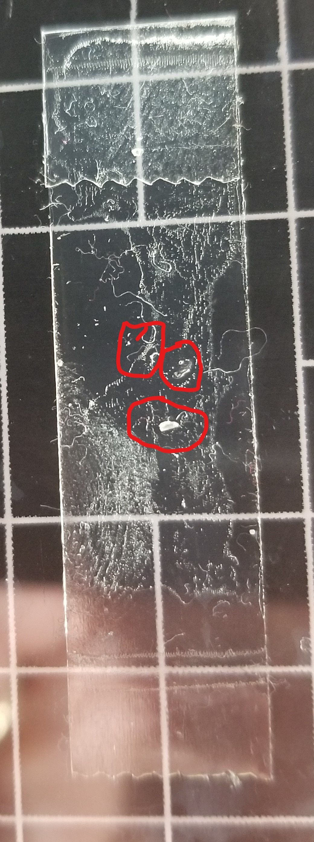
                                    @generisi There are either 2 or 3 contact spots checked very unscientifically with double stick tape on the bed when alternating T1, T0, T1, T0, ...
                                    Inked20211201_092323_LI.jpg

                                    1 Reply Last reply Reply Quote 0
                                    • GeneRisiundefined
                                      GeneRisi
                                      last edited by

                                      @t3p3tony Here is a simple print file that demonstrates T1,T0,T1,T0:

                                      G90
                                      M83
                                      M117 Preheat & Level
                                      G28
                                      G10 P0 S242 R200; set extruder 0 active and standby temps
                                      G10 P1 S242 R200; set extruder 1 active and standby temps
                                      M190 S85 ; wait for bed temperature
                                      ;mesh gcode
                                      G29 Q0
                                      T1
                                      G1 E-0.8000 F3000
                                      ; feature skirt
                                      ; tool H0.200 W0.400
                                      G1 Z0.200 F360
                                      G1 X145.575 Y112.700 F9000
                                      G1 E0.8000 F3000
                                      G1 X139.600 Y106.725 E0.2810 F90
                                      G1 X137.300 Y104.425 E0.1082
                                      G1 X137.300 Y95.575 E0.2944
                                      G1 X145.575 Y87.300 E0.3892
                                      G1 X154.425 Y87.300 E0.2944
                                      G1 X156.725 Y89.600 E0.1082
                                      G1 X162.700 Y95.575 E0.2810
                                      G1 X162.700 Y104.425 E0.2944
                                      G1 X154.425 Y112.700 E0.3892
                                      G1 X145.575 Y112.700 E0.2944
                                      G1 E-0.8000 F3000
                                      ; feature cross - external single extrusion
                                      ; tool H0.200 W0.400
                                      G1 Z0.400 F360
                                      G1 X147.738 Y100.000 F9000
                                      G1 Z0.200 F360
                                      G1 E0.8000 F3000
                                      G1 X149.641 Y100.000 E0.0633 F45
                                      G1 X150.000 Y99.641 F9000
                                      G1 X150.000 Y97.738 E0.0633 F45
                                      G1 E-0.8000 F3000
                                      G1 Z0.400 F360
                                      G1 X152.262 Y100.000 F9000
                                      G1 Z0.200 F360
                                      G1 E0.8000 F3000
                                      G1 X150.279 Y100.000 E0.0659 F45
                                      G1 X150.200 Y100.000 E0.0026
                                      ; tool H0.200 W0.416
                                      G1 X150.117 Y100.000 E0.0029
                                      ; tool H0.200 W0.499
                                      G1 X150.000 Y100.000 E0.0049
                                      G1 X150.000 Y100.117 E0.0049
                                      ; tool H0.200 W0.416
                                      G1 X150.000 Y100.200 E0.0029
                                      ; tool H0.200 W0.400
                                      G1 X150.000 Y100.279 E0.0026
                                      G1 X150.000 Y102.262 E0.0659
                                      G1 E-0.8000 F3000
                                      ; layer end
                                      T0;
                                      G1 E-0.8000 F3000
                                      ; feature skirt
                                      ; tool H0.200 W0.400
                                      G1 Z0.200 F360
                                      G1 X145.575 Y112.700 F9000
                                      G1 E0.8000 F3000
                                      G1 X139.600 Y106.725 E0.2810 F90
                                      G1 X137.300 Y104.425 E0.1082
                                      G1 X137.300 Y95.575 E0.2944
                                      G1 X145.575 Y87.300 E0.3892
                                      G1 X154.425 Y87.300 E0.2944
                                      G1 X156.725 Y89.600 E0.1082
                                      G1 X162.700 Y95.575 E0.2810
                                      G1 X162.700 Y104.425 E0.2944
                                      G1 X154.425 Y112.700 E0.3892
                                      G1 X145.575 Y112.700 E0.2944
                                      G1 E-0.8000 F3000
                                      ; feature cross - external single extrusion
                                      ; tool H0.200 W0.400
                                      G1 Z0.400 F360
                                      G1 X147.738 Y100.000 F9000
                                      G1 Z0.200 F360
                                      G1 E0.8000 F3000
                                      G1 X149.641 Y100.000 E0.0633 F45
                                      G1 X150.000 Y99.641 F9000
                                      G1 X150.000 Y97.738 E0.0633 F45
                                      G1 E-0.8000 F3000
                                      G1 Z0.400 F360
                                      G1 X152.262 Y100.000 F9000
                                      G1 Z0.200 F360
                                      G1 E0.8000 F3000
                                      G1 X150.279 Y100.000 E0.0659 F45
                                      G1 X150.200 Y100.000 E0.0026
                                      ; tool H0.200 W0.416
                                      G1 X150.117 Y100.000 E0.0029
                                      ; tool H0.200 W0.499
                                      G1 X150.000 Y100.000 E0.0049
                                      G1 X150.000 Y100.117 E0.0049
                                      ; tool H0.200 W0.416
                                      G1 X150.000 Y100.200 E0.0029
                                      ; tool H0.200 W0.400
                                      G1 X150.000 Y100.279 E0.0026
                                      G1 X150.000 Y102.262 E0.0659
                                      G1 E-0.8000 F3000
                                      ; layer end
                                      ; pass 2
                                      T1
                                      G1 E-0.8000 F3000
                                      ; feature skirt
                                      ; tool H0.200 W0.400
                                      G1 Z0.200 F360
                                      G1 X145.575 Y112.700 F9000
                                      G1 E0.8000 F3000
                                      G1 X139.600 Y106.725 E0.2810 F90
                                      G1 X137.300 Y104.425 E0.1082
                                      G1 X137.300 Y95.575 E0.2944
                                      G1 X145.575 Y87.300 E0.3892
                                      G1 X154.425 Y87.300 E0.2944
                                      G1 X156.725 Y89.600 E0.1082
                                      G1 X162.700 Y95.575 E0.2810
                                      G1 X162.700 Y104.425 E0.2944
                                      G1 X154.425 Y112.700 E0.3892
                                      G1 X145.575 Y112.700 E0.2944
                                      G1 E-0.8000 F3000
                                      ; feature cross - external single extrusion
                                      ; tool H0.200 W0.400
                                      G1 Z0.400 F360
                                      G1 X147.738 Y100.000 F9000
                                      G1 Z0.200 F360
                                      G1 E0.8000 F3000
                                      G1 X149.641 Y100.000 E0.0633 F45
                                      G1 X150.000 Y99.641 F9000
                                      G1 X150.000 Y97.738 E0.0633 F45
                                      G1 E-0.8000 F3000
                                      G1 Z0.400 F360
                                      G1 X152.262 Y100.000 F9000
                                      G1 Z0.200 F360
                                      G1 E0.8000 F3000
                                      G1 X150.279 Y100.000 E0.0659 F45
                                      G1 X150.200 Y100.000 E0.0026
                                      ; tool H0.200 W0.416
                                      G1 X150.117 Y100.000 E0.0029
                                      ; tool H0.200 W0.499
                                      G1 X150.000 Y100.000 E0.0049
                                      G1 X150.000 Y100.117 E0.0049
                                      ; tool H0.200 W0.416
                                      G1 X150.000 Y100.200 E0.0029
                                      ; tool H0.200 W0.400
                                      G1 X150.000 Y100.279 E0.0026
                                      G1 X150.000 Y102.262 E0.0659
                                      G1 E-0.8000 F3000
                                      ; layer end
                                      T0;
                                      G1 E-0.8000 F3000
                                      ; feature skirt
                                      ; tool H0.200 W0.400
                                      G1 Z0.200 F360
                                      G1 X145.575 Y112.700 F9000
                                      G1 E0.8000 F3000
                                      G1 X139.600 Y106.725 E0.2810 F90
                                      G1 X137.300 Y104.425 E0.1082
                                      G1 X137.300 Y95.575 E0.2944
                                      G1 X145.575 Y87.300 E0.3892
                                      G1 X154.425 Y87.300 E0.2944
                                      G1 X156.725 Y89.600 E0.1082
                                      G1 X162.700 Y95.575 E0.2810
                                      G1 X162.700 Y104.425 E0.2944
                                      G1 X154.425 Y112.700 E0.3892
                                      G1 X145.575 Y112.700 E0.2944
                                      G1 E-0.8000 F3000
                                      ; feature cross - external single extrusion
                                      ; tool H0.200 W0.400
                                      G1 Z0.400 F360
                                      G1 X147.738 Y100.000 F9000
                                      G1 Z0.200 F360
                                      G1 E0.8000 F3000
                                      G1 X149.641 Y100.000 E0.0633 F45
                                      G1 X150.000 Y99.641 F9000
                                      G1 X150.000 Y97.738 E0.0633 F45
                                      G1 E-0.8000 F3000
                                      G1 Z0.400 F360
                                      G1 X152.262 Y100.000 F9000
                                      G1 Z0.200 F360
                                      G1 E0.8000 F3000
                                      G1 X150.279 Y100.000 E0.0659 F45
                                      G1 X150.200 Y100.000 E0.0026
                                      ; tool H0.200 W0.416
                                      G1 X150.117 Y100.000 E0.0029
                                      ; tool H0.200 W0.499
                                      G1 X150.000 Y100.000 E0.0049
                                      G1 X150.000 Y100.117 E0.0049
                                      ; tool H0.200 W0.416
                                      G1 X150.000 Y100.200 E0.0029
                                      ; tool H0.200 W0.400
                                      G1 X150.000 Y100.279 E0.0026
                                      G1 X150.000 Y102.262 E0.0659
                                      G1 E-0.8000 F3000
                                      ; layer end
                                      M117 Print Complete !
                                      T-1
                                      M999
                                      

                                      Simple_cross.jpg

                                      dc42undefined 1 Reply Last reply Reply Quote 1
                                      • dc42undefined
                                        dc42 administrators @GeneRisi
                                        last edited by

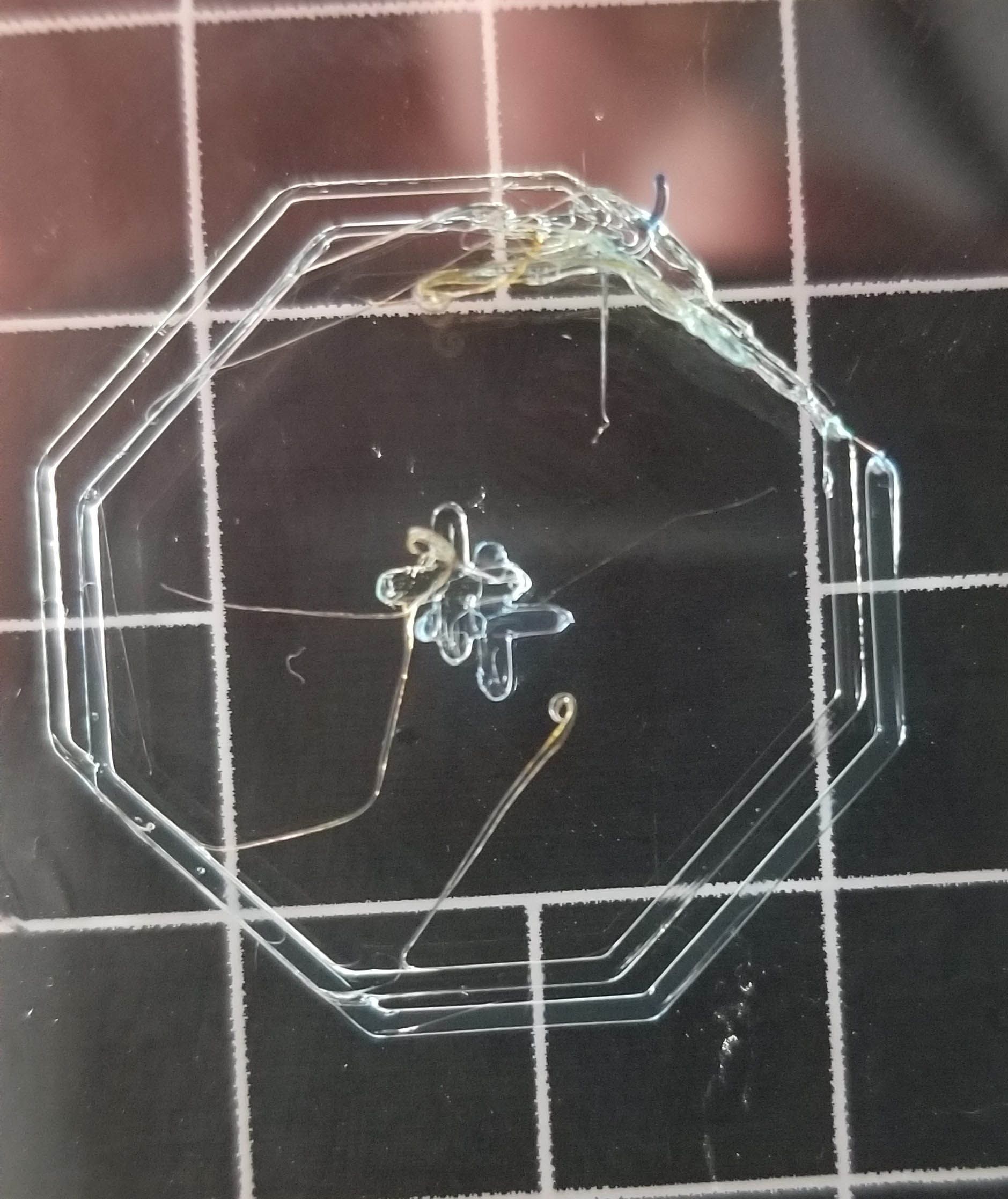
                                        @generisi please post your tool change files again, because you have changed them since you posted them.

                                        Duet WiFi hardware designer and firmware engineer
                                        Please do not ask me for Duet support via PM or email, use the forum
                                        http://www.escher3d.com, https://miscsolutions.wordpress.com

                                        GeneRisiundefined 1 Reply Last reply Reply Quote 0
                                        • GeneRisiundefined
                                          GeneRisi @dc42
                                          last edited by GeneRisi

                                          @dc42 OK, I will now

                                          ; tpost0.g
                                          ; called after tool 0 has been selected
                                          
                                          ;heatup
                                          M116 P0
                                          
                                          ;prime nozzle
                                          ;M98 Pprime.g
                                          
                                          ;mesh levelling on
                                          G29 Q1
                                          
                                          ;PCF fan on
                                          ;M106 P2 S255
                                          
                                          G1 R2 X0 Y0 Z2
                                          G1 R2 Z0 F360
                                          
                                          ; tpost1.g
                                          ; called after tool 1 has been selected
                                          
                                          ;heatup
                                          M116 P1
                                          
                                          ;prime nozzle
                                          ;M98 Pprime.g
                                          
                                          ;mesh levelling on
                                          G29 Q1
                                          
                                          ;PCF fan on
                                          ;M106 P4 S255
                                          G1 R2 X0 Y0 Z2
                                          G1 R2 Z0 F360
                                          

                                          The Free and pre files have not changed.

                                          T3P3Tonyundefined 1 Reply Last reply Reply Quote 0
                                          • T3P3Tonyundefined
                                            T3P3Tony administrators @GeneRisi
                                            last edited by

                                            @generisi with the image with the two cross prints you showed. Do you mean that T0 and T1 printed one of the crosses perfectly aligned and then the next time T1 was used it printed the miss aligned cross?

                                            www.duet3d.com

                                            GeneRisiundefined 1 Reply Last reply Reply Quote 0
                                            • First post
                                              Last post
                                            Unless otherwise noted, all forum content is licensed under CC-BY-SA