Dumbfounded ! Firmware bug in 3.4 beta 6?
-
@t3p3tony Hi Tony - I have my own "mesh.g" macro that allows me to also use "Q1" and "Q2" as inputs. I use the macro to check that the bed mesh in use has been created after the most recent system reset and is not being used if it was created some time before the most recent reset.
; mesh.g
;
; Redefining G29 behavior
; New parameter Q is used as a substitute for S so that this macro is called
; 	no parms or Q0 means probe mesh, save it but don't load it now
; 	Q1 means use mesh compensation if is fresh
; 	Q2 means disable mesh compensation
;       global.freshMesh set to false in config.g
;
var qVal = 0
if exists(param.Q)
	set var.qVal = param.Q
if var.qVal = 0
	if !move.axes[0].homed | !move.axes[1].homed | !move.axes[2].homed
		abort "Home all axes before running mesh probes"
	else
		G91;
		G1 Z5 F500
		G90;
		G29 S2 ; make sure mesh compensations is off
		G1 X150 Y100 F3000
		G30 ;  get fresh Z=0 for current conditions
		set global.freshMesh = true
elif var.qVal = 1 & global.freshMesh = false
	abort "Trying to use old height map, that's not ok right now"
;
echo "G29 S", {var.qVal}
G29 S{var.qVal}
;
if var.qVal = 0
	G29 S2					; disable mesh compensation for now if no parms or mesh probed and saved
;
; finis
Also, is there a reason why you did not combine the two "G1 R2 ..." commands into a single command?
I will try your suggestion. Thanks!
-
@generisi said in Dumbfounded ! Firmware bug in 3.4 beta 6?:
I have my own "mesh.g" macro that allows me to also use "Q1" and "Q2" as inputs. I use the macro to check that the bed mesh in use has been created after the most recent system reset and is not being used if it was created some time before the most recent reset.
ok i did not realise that - nice use case!
@generisi said in Dumbfounded ! Firmware bug in 3.4 beta 6?:
is there a reason why you did not combine the two "G1 R2 ..." commands into a single command?
restoring it in the way I showed, with some Z lift first, is what we recommend for most use cases as it means the last axis to move into position will be Z, so there is less change of the tool dragging across the top of the print as the position is restored.
-
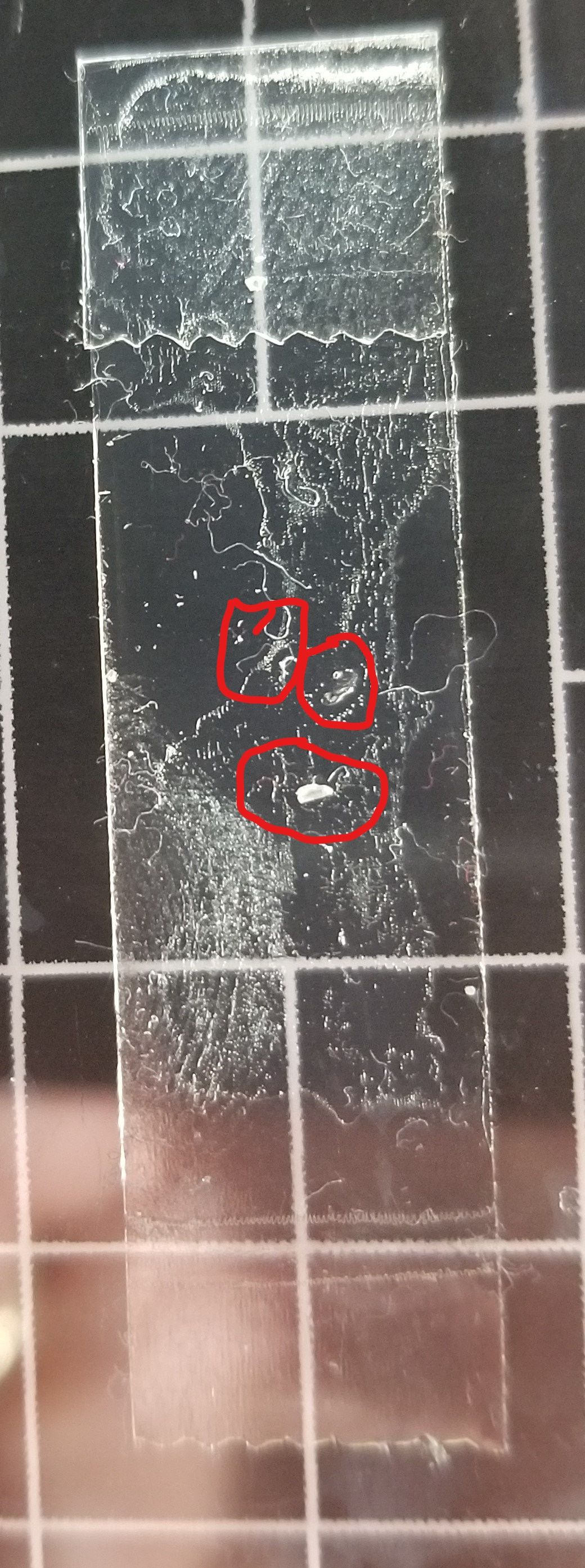
@generisi There are either 2 or 3 contact spots checked very unscientifically with double stick tape on the bed when alternating T1, T0, T1, T0, ...
-
@t3p3tony Here is a simple print file that demonstrates T1,T0,T1,T0:
G90
M83
M117 Preheat & Level
G28
G10 P0 S242 R200; set extruder 0 active and standby temps
G10 P1 S242 R200; set extruder 1 active and standby temps
M190 S85 ; wait for bed temperature
;mesh gcode
G29 Q0
T1
G1 E-0.8000 F3000
; feature skirt
; tool H0.200 W0.400
G1 Z0.200 F360
G1 X145.575 Y112.700 F9000
G1 E0.8000 F3000
G1 X139.600 Y106.725 E0.2810 F90
G1 X137.300 Y104.425 E0.1082
G1 X137.300 Y95.575 E0.2944
G1 X145.575 Y87.300 E0.3892
G1 X154.425 Y87.300 E0.2944
G1 X156.725 Y89.600 E0.1082
G1 X162.700 Y95.575 E0.2810
G1 X162.700 Y104.425 E0.2944
G1 X154.425 Y112.700 E0.3892
G1 X145.575 Y112.700 E0.2944
G1 E-0.8000 F3000
; feature cross - external single extrusion
; tool H0.200 W0.400
G1 Z0.400 F360
G1 X147.738 Y100.000 F9000
G1 Z0.200 F360
G1 E0.8000 F3000
G1 X149.641 Y100.000 E0.0633 F45
G1 X150.000 Y99.641 F9000
G1 X150.000 Y97.738 E0.0633 F45
G1 E-0.8000 F3000
G1 Z0.400 F360
G1 X152.262 Y100.000 F9000
G1 Z0.200 F360
G1 E0.8000 F3000
G1 X150.279 Y100.000 E0.0659 F45
G1 X150.200 Y100.000 E0.0026
; tool H0.200 W0.416
G1 X150.117 Y100.000 E0.0029
; tool H0.200 W0.499
G1 X150.000 Y100.000 E0.0049
G1 X150.000 Y100.117 E0.0049
; tool H0.200 W0.416
G1 X150.000 Y100.200 E0.0029
; tool H0.200 W0.400
G1 X150.000 Y100.279 E0.0026
G1 X150.000 Y102.262 E0.0659
G1 E-0.8000 F3000
; layer end
T0;
G1 E-0.8000 F3000
; feature skirt
; tool H0.200 W0.400
G1 Z0.200 F360
G1 X145.575 Y112.700 F9000
G1 E0.8000 F3000
G1 X139.600 Y106.725 E0.2810 F90
G1 X137.300 Y104.425 E0.1082
G1 X137.300 Y95.575 E0.2944
G1 X145.575 Y87.300 E0.3892
G1 X154.425 Y87.300 E0.2944
G1 X156.725 Y89.600 E0.1082
G1 X162.700 Y95.575 E0.2810
G1 X162.700 Y104.425 E0.2944
G1 X154.425 Y112.700 E0.3892
G1 X145.575 Y112.700 E0.2944
G1 E-0.8000 F3000
; feature cross - external single extrusion
; tool H0.200 W0.400
G1 Z0.400 F360
G1 X147.738 Y100.000 F9000
G1 Z0.200 F360
G1 E0.8000 F3000
G1 X149.641 Y100.000 E0.0633 F45
G1 X150.000 Y99.641 F9000
G1 X150.000 Y97.738 E0.0633 F45
G1 E-0.8000 F3000
G1 Z0.400 F360
G1 X152.262 Y100.000 F9000
G1 Z0.200 F360
G1 E0.8000 F3000
G1 X150.279 Y100.000 E0.0659 F45
G1 X150.200 Y100.000 E0.0026
; tool H0.200 W0.416
G1 X150.117 Y100.000 E0.0029
; tool H0.200 W0.499
G1 X150.000 Y100.000 E0.0049
G1 X150.000 Y100.117 E0.0049
; tool H0.200 W0.416
G1 X150.000 Y100.200 E0.0029
; tool H0.200 W0.400
G1 X150.000 Y100.279 E0.0026
G1 X150.000 Y102.262 E0.0659
G1 E-0.8000 F3000
; layer end
; pass 2
T1
G1 E-0.8000 F3000
; feature skirt
; tool H0.200 W0.400
G1 Z0.200 F360
G1 X145.575 Y112.700 F9000
G1 E0.8000 F3000
G1 X139.600 Y106.725 E0.2810 F90
G1 X137.300 Y104.425 E0.1082
G1 X137.300 Y95.575 E0.2944
G1 X145.575 Y87.300 E0.3892
G1 X154.425 Y87.300 E0.2944
G1 X156.725 Y89.600 E0.1082
G1 X162.700 Y95.575 E0.2810
G1 X162.700 Y104.425 E0.2944
G1 X154.425 Y112.700 E0.3892
G1 X145.575 Y112.700 E0.2944
G1 E-0.8000 F3000
; feature cross - external single extrusion
; tool H0.200 W0.400
G1 Z0.400 F360
G1 X147.738 Y100.000 F9000
G1 Z0.200 F360
G1 E0.8000 F3000
G1 X149.641 Y100.000 E0.0633 F45
G1 X150.000 Y99.641 F9000
G1 X150.000 Y97.738 E0.0633 F45
G1 E-0.8000 F3000
G1 Z0.400 F360
G1 X152.262 Y100.000 F9000
G1 Z0.200 F360
G1 E0.8000 F3000
G1 X150.279 Y100.000 E0.0659 F45
G1 X150.200 Y100.000 E0.0026
; tool H0.200 W0.416
G1 X150.117 Y100.000 E0.0029
; tool H0.200 W0.499
G1 X150.000 Y100.000 E0.0049
G1 X150.000 Y100.117 E0.0049
; tool H0.200 W0.416
G1 X150.000 Y100.200 E0.0029
; tool H0.200 W0.400
G1 X150.000 Y100.279 E0.0026
G1 X150.000 Y102.262 E0.0659
G1 E-0.8000 F3000
; layer end
T0;
G1 E-0.8000 F3000
; feature skirt
; tool H0.200 W0.400
G1 Z0.200 F360
G1 X145.575 Y112.700 F9000
G1 E0.8000 F3000
G1 X139.600 Y106.725 E0.2810 F90
G1 X137.300 Y104.425 E0.1082
G1 X137.300 Y95.575 E0.2944
G1 X145.575 Y87.300 E0.3892
G1 X154.425 Y87.300 E0.2944
G1 X156.725 Y89.600 E0.1082
G1 X162.700 Y95.575 E0.2810
G1 X162.700 Y104.425 E0.2944
G1 X154.425 Y112.700 E0.3892
G1 X145.575 Y112.700 E0.2944
G1 E-0.8000 F3000
; feature cross - external single extrusion
; tool H0.200 W0.400
G1 Z0.400 F360
G1 X147.738 Y100.000 F9000
G1 Z0.200 F360
G1 E0.8000 F3000
G1 X149.641 Y100.000 E0.0633 F45
G1 X150.000 Y99.641 F9000
G1 X150.000 Y97.738 E0.0633 F45
G1 E-0.8000 F3000
G1 Z0.400 F360
G1 X152.262 Y100.000 F9000
G1 Z0.200 F360
G1 E0.8000 F3000
G1 X150.279 Y100.000 E0.0659 F45
G1 X150.200 Y100.000 E0.0026
; tool H0.200 W0.416
G1 X150.117 Y100.000 E0.0029
; tool H0.200 W0.499
G1 X150.000 Y100.000 E0.0049
G1 X150.000 Y100.117 E0.0049
; tool H0.200 W0.416
G1 X150.000 Y100.200 E0.0029
; tool H0.200 W0.400
G1 X150.000 Y100.279 E0.0026
G1 X150.000 Y102.262 E0.0659
G1 E-0.8000 F3000
; layer end
M117 Print Complete !
T-1
M999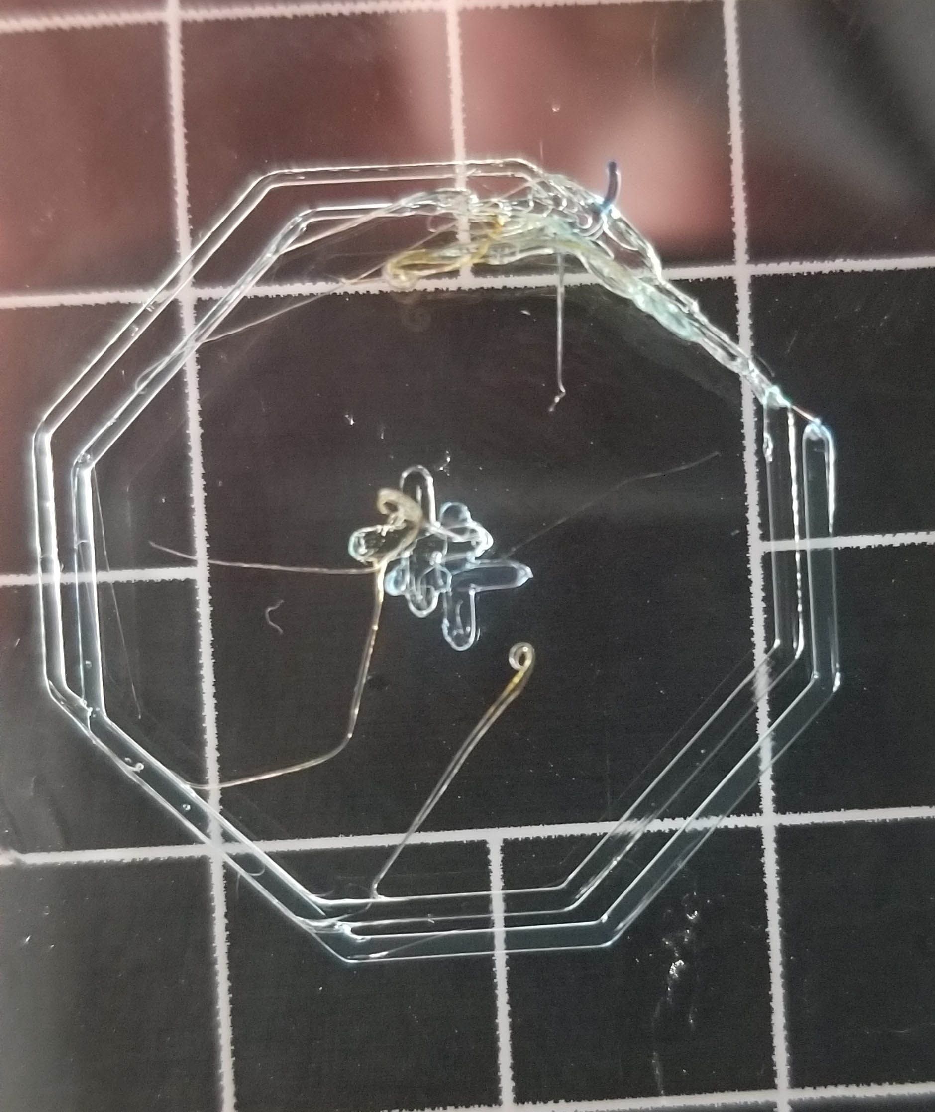
-
@generisi please post your tool change files again, because you have changed them since you posted them.
Duet WiFi hardware designer and firmware engineer
Please do not ask me for Duet support via PM or email, use the forum
http://www.escher3d.com, https://miscsolutions.wordpress.com -
@dc42 OK, I will now
; tpost0.g
; called after tool 0 has been selected

;heatup
M116 P0

;prime nozzle
;M98 Pprime.g

;mesh levelling on
G29 Q1

;PCF fan on
;M106 P2 S255

G1 R2 X0 Y0 Z2
G1 R2 Z0 F360
; tpost1.g ; called after tool 1 has been selected ;heatup M116 P1 ;prime nozzle ;M98 Pprime.g ;mesh levelling on G29 Q1 ;PCF fan on ;M106 P4 S255 G1 R2 X0 Y0 Z2 G1 R2 Z0 F360The Free and pre files have not changed.
-
@generisi with the image with the two cross prints you showed. Do you mean that T0 and T1 printed one of the crosses perfectly aligned and then the next time T1 was used it printed the miss aligned cross?
-
@t3p3tony Hi Tony, T1 printed the cross in one location and T0 printed the cross in the other location. Even when repeating the sequence a second time, T1 prints in one location and T0 in the other location.
If the order is switched, so that T0 is used first, then T1, the crosses align as expected. This is also true if the sequence is T0, T1, T0, T1.
FWIW, many years ago, I used to be a programmer and when I think about this, uninitialized values that are referenced comes to mind... FWIW
@dc42 , is there some level of debugging I can turn on that might provide you some helpful information?
-
 undefined Phaedrux marked this topic as a question
-
@generisi I have a theory about what us happening. Tool offsets are usually ignored in system macro files. So I think the G1 R2 X0 Y0 Z0 command at the end of config.g is ignoring the tool offsets. This obviously isn't wanted in this case.
I will do some tests to confirm or refute this theory.
Duet WiFi hardware designer and firmware engineer
Please do not ask me for Duet support via PM or email, use the forum
http://www.escher3d.com, https://miscsolutions.wordpress.com -
@dc42 I only added this line after the exchange with @T3P3Tony above; I did, however, use G1 R2 Z0 before communicating with Tony. As an alternative, I can remove the G1 R2 command and use Simplify3d's internal state variables to restore the X, Y and Z locations. Let me know whether this would be a helpful test.
GeneI removed the G1 R2 commands from the tpostx macros. It didn't change the outcome.
GeneWhy would the tool offsets matter for a move that simply gets the new tool head near the area where it will be used? The printing doesn't occur until a few gcode commands after this move. Aren't the tool offsets applied to every gcode move command?
Gene -
@dc42 Is there something I can do t help debugging this?
-
@dc42 I found the problem.
When tool T1 was being returned, the Y "parking" coordinate was off by 1 mm. The tool parking location didn't budge but the firmware thought that the tool location was 1mm beyond where it actually was. The machine is a corexy (E3D), so even though only the Y coordinate was off, I suspect it affected both the x and y location from the the firmware's perspective.
-
 undefined GeneRisi has marked this topic as solved