Duet3D Logo Duet3D
    • Tags
    • Documentation
    • Order
    • Register
    • Login

    seeing if i can get assistance with bed connectins

    Scheduled Pinned Locked Moved
    Duet Hardware and wiring
    6
    63
    1.5k
    Loading More Posts
    • Oldest to Newest
    • Newest to Oldest
    • Most Votes
    Reply
    • Reply as topic
    Log in to reply
    This topic has been deleted. Only users with topic management privileges can see it.
    • frnknstnundefined
      frnknstn @frnknstn
      last edited by

      @frnknstn 2cf66c9f-c9d2-48bb-a684-8203d01153e6-Screenshot (5).png

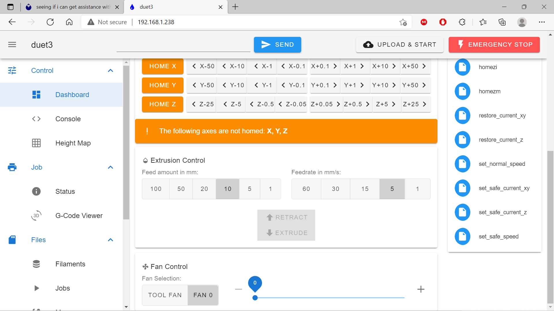
      it put Tool fan under fans. No movement yet though

      Gixxerfastundefined 1 Reply Last reply Reply Quote 0
      • Gixxerfastundefined
        Gixxerfast @frnknstn
        last edited by Gixxerfast

        @frnknstn Oh, yes. #2 done. Now try to max that one and see if any fan spins.

        Drag it to max

        Voron V2.4 (#1317) with Duet 3 Mini5+ Wifi and 1LC v1.1 Toolboard
        Voron V0.1 (#637) with Duet 3 Mini 5+ Wifi and 1LC v1.2 Toolboard
        Ender 3 Pro with BTT SKR-2 + RRF

        frnknstnundefined 1 Reply Last reply Reply Quote 0
        • frnknstnundefined
          frnknstn @Gixxerfast
          last edited by

          @gixxerfast no movement.

          ; General preferences
          G90                                         ; Send absolute coordinates...
          M83                                         ; ...but relative extruder moves
          
          ; Network
          M550 P"duet3"                        	; Set machine name
          M552 S1                                     	; Enable network
          ;*** Access point is configured manually via M587
          M586 P0 S1                                  ; Enable HTTP
          M586 P1 S0                                  ; Disable FTP
          M586 P2 S0                                  ; Disable Telnet
          M575 P1 S1 B57600							; Panel Due
          
          ; Printer geometry
          M669 K1                	                    ; Select CoreXY mode
          M208 X0:330 Y0:285.75 Z0:350                ; Axis Limits
          M564 H0							            ; allow unhomed movement
          
          ;------- drives from top---------------------------------------------------
          ;  B -------+------ A   
          ;   | P.02 | P.03 |
          ;   -------+-------  Z-Drives
          ;   | P0.1 | P0.4 |
          ;   -------+-------
          ;        Front
          
          ; Drive Mappings
          M569 P0.0 S1 V0                             ; Drive 0: E Axis
          M569 P0.1 S1 V0                             ; Drive 1: Z-LeftFront Axis
          M569 P0.2 S0 V0                             ; Drive 2: Z-LeftRear Axis
          M569 P0.3 S1 V0                             ; Drive 3: Z-RightRear Axis
          M569 P0.4 S0 V0                             ; Drive 4: Z-RightFront Axis
          M569 P1.0 S1 V0                             ; Drive 5: Expansion: B motor (X-axis)
          M569 P1.1 S1 V0                             ; Drive 6: Expansion: A motor (Y-axis)
          
          
          ; Motor remapping for dual Z and axis Limits
          M584 X1.0 Y1.1 Z0.1:0.2:0.3:0.4 E0.0                              ; Motor mapping
          M671 X-76.2:-76.2:406.4:406.4 Y0:374.65:374.65:0 S20	        ; Z leadscrews positions Left Front - Let Rear - Right Rear - Right Front
          
          ; Microstepping and Speed
          M350 X32 Y32 E16 Z16 I1                     ; Configure microstepping with interpolation   
          M92 X200.00 Y200.00 Z200.00 E400.00         ; Set steps per mm	1.8 motors							
          
          ; Speeds, Acceleration and Jerk
          M566 X400.00 Y400.00 Z25.00 E600.00 P1          ; Set maximum instantaneous speed changes (mm/min)
          M203 X12000.00 Y12000.00 Z1000.00 E3600.00      ; Set maximum speeds (mm/min)
          M201 X3000.00 Y3000.00 Z100.00 E3600.00        ; Set accelerations (mm/s^2)
          
          ; Motor currents
          M906 X1200.00 Y1200.00 Z1200.00 E700.00 I60        ; Set motor currents (mA) and motor idle factor in percent 
          M84 S600                                            ; Set idle timeout
          
          ; Endstops for each Axis
          M574 X2 S1 P"io0.in" 					 	; Set X endstop controlled by switch
          M574 Y2 S1 P"io1.in"                      	; Set Y endstop controlled by switch
          
          ; Z-Probe
          M558 P8 C"io3.in" H5 F120 T60000                                 ; set Z probe type to unmodulated and the dive height + speeds
          G31 P500 X0 Y0 Z2.5                                                 ; set Z probe trigger value, offset and trigger height
          M557 X15:215 Y15:195 S20                                            ; define mesh grid


          ; Stallgaurd Sensitivy (maybe use to pause print after crash)
          M915 X S2 F0 H200 R0		                ; Set X axis Sensitivity  1.8 motors
          M915 Y S2 F0 H200 R0		                ; Set y axis Sensitivity  1.8 motors
          
          ; Input Shaper and Accelerometer
          ;M955 P0 C"io4.out+io4.in"
          ;M593 F46.75 S0.2
          ;M593 F19 P4 S0.3 ; experimental 
                           
          
          ; Z Probe Offset (Probe behind Afterburner)
          G31 P500 X0 Y0 Z1.5
          
          ; Heaters
          M308 S0 P"temp_0" Y"thermistor" A"Bed" T100000 B4138                ; configure sensor 0 as thermistor on pin temp0
          M950 H0 C"out_0" T0                                                 ; create bed heater output on out0 and map it to sensor 0                                             
          M307 H0 A350 C139 D5.5 B0 ; set model parameters for heater 1 and use PID mode
          M140 H0                                                            ; map heated bed to heater 0
          M143 H0 S120                                                       ; set temperature limit for heater 0 to 120C
          
          M308 S1 P"temp_1" Y"thermistor"  A"Hotend" T100000 B4725 C7.06e-8   ; configure sensor 1 as thermistor on pin temp1
          M950 H1 C"out_1" T1                                                 ; create nozzle heater output on out1 and map it to sensor 1
          M307 H1 B0 R1.680 C233.0:193.0 D6.75 S1.00 V23.7                   ; disable bang-bang mode for heater  and set PWM limit                                                     
          M143 H1 S280                                                       ; set temperature limit for heater 1 to 280C
          
          
          ; Fans
          M950 F0 C"out7" Q500                                     ; Parts cooling create fan 0 on pin out7 and set its frequency
          M106 P0 S0 H-1                                           
          
          M950 F1 C"out8" Q500                                     ; Extruder create fan 1 on pin out8 and set its frequency
          M106 P1 T25 H1                                           
          
          
          ; Fans Electronic compartment & Exhaust
          ;M950 F1 C"out3" Q100				    ; Creates Case Fan 1
          ;M106 P1 T40 S150 H0                 ; Case Fan 1 Settings (Turns on at 60°C tool temp) at low speed
          ;M950 F2 C"out4" Q100				    ; Creates Case Fan 2
          ;M106 P2 T40 S150 H0                  ; Case Fan 2 Settings (Turns on at 60°C tool temp) at low speed
          ;M950 F5 C"out7" Q100				    ; Creates Case Fan 2
          ;M106 P5 T95 S50 H0                  ; Exhaust fan
          
          ; Filament Runout sensor
          ;M950 J4 C"io5.in"               ; Input 4 filament sensor
          ;M581 P4 T2 S1 R1                ; Filament Sensor P4 triggers  inactive-to-active edge (S1) tigger2.g (T2) only when printing (R1)
          ;M591 D0 P1 C"io5.in" S1			; Filament Sensor 
          
          ; Tools
          M563 P0 D0 H1
          G10 P0 X0 Y0 Z0                             ; Set tool 0 axis offsets
          G10 P0 R0 S0                                ; Set initial tool 0 active and standby temperatures to 0C
          T0


          Gixxerfastundefined 1 Reply Last reply Reply Quote 0
          • Gixxerfastundefined
            Gixxerfast @frnknstn
            last edited by Gixxerfast

            @frnknstn OK, so you have dragged the little bubble icon to max and no fan movement?

            Then we need to see the wiring please

            Your fan config should be good now

            Promise to say "It's alive, it's alive" when it starts working 🙂

            Voron V2.4 (#1317) with Duet 3 Mini5+ Wifi and 1LC v1.1 Toolboard
            Voron V0.1 (#637) with Duet 3 Mini 5+ Wifi and 1LC v1.2 Toolboard
            Ender 3 Pro with BTT SKR-2 + RRF

            frnknstnundefined 2 Replies Last reply Reply Quote 0
            • frnknstnundefined
              frnknstn @Gixxerfast
              last edited by

              @gixxerfast could i have the wires backwards wouldnt they spin backwards? Probably a dumb question but i thought id ask. Trying to get this pic off my phone to show ya

              Gixxerfastundefined 1 Reply Last reply Reply Quote 0
              • frnknstnundefined
                frnknstn @Gixxerfast
                last edited by

                @gixxerfast said in seeing if i can get assistance with bed connectins:

                @frnknstn OK, so you have dragged the little bubble icon to max and no fan movement?

                Then we need to see the wiring please

                Your fan config should be good now

                Promise to say "It's alive, it's alive" when it starts working 🙂

                Funny cause i call it Frankenstein

                Gixxerfastundefined 2 Replies Last reply Reply Quote 0
                • Gixxerfastundefined
                  Gixxerfast @frnknstn
                  last edited by

                  @frnknstn No, they don't spin backwards AFAIK. They can actually be really sad sometimes if wired incorrectly (afaik)

                  Voron V2.4 (#1317) with Duet 3 Mini5+ Wifi and 1LC v1.1 Toolboard
                  Voron V0.1 (#637) with Duet 3 Mini 5+ Wifi and 1LC v1.2 Toolboard
                  Ender 3 Pro with BTT SKR-2 + RRF

                  frnknstnundefined 1 Reply Last reply Reply Quote 0
                  • Gixxerfastundefined
                    Gixxerfast @frnknstn
                    last edited by

                    @frnknstn said in seeing if i can get assistance with bed connectins:

                    Funny cause i call it Frankenstein

                    Yeah, that's why it's fun 🙂 LOL

                    Voron V2.4 (#1317) with Duet 3 Mini5+ Wifi and 1LC v1.1 Toolboard
                    Voron V0.1 (#637) with Duet 3 Mini 5+ Wifi and 1LC v1.2 Toolboard
                    Ender 3 Pro with BTT SKR-2 + RRF

                    1 Reply Last reply Reply Quote 0
                    • frnknstnundefined
                      frnknstn @Gixxerfast
                      last edited by

                      @gixxerfast alright i have to pause here...i have to grab the wife from work then i will be back, again i appreciate it alot.

                      1 Reply Last reply Reply Quote 0
                      • Gixxerfastundefined
                        Gixxerfast @frnknstn
                        last edited by

                        @frnknstn OK, anyhow. The black wire should be facing the SD-card when connected to the two pin connectors.

                        Voron V2.4 (#1317) with Duet 3 Mini5+ Wifi and 1LC v1.1 Toolboard
                        Voron V0.1 (#637) with Duet 3 Mini 5+ Wifi and 1LC v1.2 Toolboard
                        Ender 3 Pro with BTT SKR-2 + RRF

                        frnknstnundefined 1 Reply Last reply Reply Quote 0
                        • frnknstnundefined
                          frnknstn @Gixxerfast
                          last edited by

                          @gixxerfast so i had out7 backwards. i swapped the wires around and now the parts blower work. on control panel tool fan and fan 0 turn it on. out8 nothing

                          frnknstnundefined 1 Reply Last reply Reply Quote 0
                          • frnknstnundefined
                            frnknstn @frnknstn
                            last edited by

                            @frnknstn said in seeing if i can get assistance with bed connectins:

                            @gixxerfast so i had out7 backwards. i swapped the wires around and now the parts blower work. on control panel tool fan and fan 0 turn it on. out8 nothing

                            also i checked wiring they are both black towards sd card slot

                            frnknstnundefined 1 Reply Last reply Reply Quote 0
                            • frnknstnundefined
                              frnknstn @frnknstn
                              last edited by

                              @frnknstn sorry i was incorrect 8 was backwards too

                              frnknstnundefined 1 Reply Last reply Reply Quote 0
                              • frnknstnundefined
                                frnknstn @frnknstn
                                last edited by

                                @frnknstn fixedfan 8 now 7 is controlled by both fan controls

                                frnknstnundefined 1 Reply Last reply Reply Quote 0
                                • frnknstnundefined
                                  frnknstn @frnknstn
                                  last edited by

                                  @frnknstn ```
                                  As of right now my extruder fan is on always, the other fan comes on with the control buttons

                                  ; Fans
                                  M950 F0 C"out7" Q500                                     ; Parts cooling create fan 0 on pin out7 and set its frequency
                                  M106 P0 S0 H-1                                           
                                  
                                  M950 F1 C"out8" Q500                                     ; Extruder create fan 1 on pin out8 and set its frequency
                                  M106 P1 T0 H1
                                  frnknstnundefined Gixxerfastundefined 2 Replies Last reply Reply Quote 0
                                  • frnknstnundefined
                                    frnknstn @frnknstn
                                    last edited by

                                    @frnknstn i see tool fan is only active while hotend is active

                                    Phaedruxundefined 1 Reply Last reply Reply Quote 0
                                    • Phaedruxundefined
                                      Phaedrux Moderator @frnknstn
                                      last edited by

                                      @frnknstn said in seeing if i can get assistance with bed connectins:

                                      Show us your tool definition.

                                      Z-Bot CoreXY Build | Thingiverse Profile

                                      1 Reply Last reply Reply Quote 0
                                      • Gixxerfastundefined
                                        Gixxerfast @frnknstn
                                        last edited by

                                        @frnknstn said in seeing if i can get assistance with bed connectins:

                                        M106 P1 T0 H1

                                        As far as I can see all is working as it should. Maybe you could have the hotend fan turn on at 45C something like this:

                                        M106 P1 S1 H1 T45
                                        

                                        Apart from that, don't you think the fans are working as they should now?

                                        Voron V2.4 (#1317) with Duet 3 Mini5+ Wifi and 1LC v1.1 Toolboard
                                        Voron V0.1 (#637) with Duet 3 Mini 5+ Wifi and 1LC v1.2 Toolboard
                                        Ender 3 Pro with BTT SKR-2 + RRF

                                        frnknstnundefined 1 Reply Last reply Reply Quote 0
                                        • frnknstnundefined
                                          frnknstn @Gixxerfast
                                          last edited by

                                          @gixxerfast fans seem good. I'm going to work on z probe now to figure that out. This is my code so far

                                          G90                                         ; Send absolute coordinates...
                                          M83                                         ; ...but relative extruder moves
                                          
                                          ; Network
                                          M550 P"duet3"                        	; Set machine name
                                          M552 S1                                     	; Enable network
                                          ;*** Access point is configured manually via M587
                                          M586 P0 S1                                  ; Enable HTTP
                                          M586 P1 S0                                  ; Disable FTP
                                          M586 P2 S0                                  ; Disable Telnet
                                          M575 P1 S1 B57600							; Panel Due
                                          
                                          ; Printer geometry
                                          M669 K1                	                    ; Select CoreXY mode
                                          M208 X0:330 Y0:285.75 Z0:350                ; Axis Limits
                                          M564 H0							            ; allow unhomed movement
                                          
                                          ;------- drives from top---------------------------------------------------
                                          ;  B -------+------ A   
                                          ;   | P.02 | P.03 |
                                          ;   -------+-------  Z-Drives
                                          ;   | P0.1 | P0.4 |
                                          ;   -------+-------
                                          ;        Front
                                          
                                          ; Drive Mappings
                                          M569 P0.0 S1 V0                             ; Drive 0: E Axis
                                          M569 P0.1 S1 V0                             ; Drive 1: Z-LeftFront Axis
                                          M569 P0.2 S0 V0                             ; Drive 2: Z-LeftRear Axis
                                          M569 P0.3 S1 V0                             ; Drive 3: Z-RightRear Axis
                                          M569 P0.4 S0 V0                             ; Drive 4: Z-RightFront Axis
                                          M569 P1.0 S1 V0                             ; Drive 5: Expansion: B motor (X-axis)
                                          M569 P1.1 S1 V0                             ; Drive 6: Expansion: A motor (Y-axis)
                                          
                                          
                                          ; Motor remapping for dual Z and axis Limits
                                          M584 X1.0 Y1.1 Z0.1:0.2:0.3:0.4 E0.0                              ; Motor mapping
                                          M671 X-76.2:-76.2:406.4:406.4 Y0:374.65:374.65:0 S20	        ; Z leadscrews positions Left Front - Let Rear - Right Rear - Right Front
                                          
                                          ; Microstepping and Speed
                                          M350 X32 Y32 E16 Z16 I1                     ; Configure microstepping with interpolation   
                                          M92 X200.00 Y200.00 Z200.00 E400.00         ; Set steps per mm	1.8 motors							
                                          
                                          ; Speeds, Acceleration and Jerk
                                          M566 X400.00 Y400.00 Z25.00 E600.00 P1          ; Set maximum instantaneous speed changes (mm/min)
                                          M203 X12000.00 Y12000.00 Z1000.00 E3600.00      ; Set maximum speeds (mm/min)
                                          M201 X3000.00 Y3000.00 Z100.00 E3600.00        ; Set accelerations (mm/s^2)
                                          
                                          ; Motor currents
                                          M906 X1200.00 Y1200.00 Z1200.00 E700.00 I60        ; Set motor currents (mA) and motor idle factor in percent 
                                          M84 S600                                            ; Set idle timeout
                                          
                                          ; Endstops for each Axis
                                          M574 X2 S1 P"io0.in" 					 	; Set X endstop controlled by switch
                                          M574 Y2 S1 P"io1.in"                      	; Set Y endstop controlled by switch
                                          
                                          ; Z-Probe
                                          M558 P8 C"io3.in" H5 F120 T60000                                 ; set Z probe type to unmodulated and the dive height + speeds
                                          G31 P500 X0 Y0 Z2.5                                                 ; set Z probe trigger value, offset and trigger height
                                          M557 X15:215 Y15:195 S20                                            ; define mesh grid


                                          ; Stallgaurd Sensitivy (maybe use to pause print after crash)
                                          M915 X S2 F0 H200 R0		                ; Set X axis Sensitivity  1.8 motors
                                          M915 Y S2 F0 H200 R0		                ; Set y axis Sensitivity  1.8 motors
                                          
                                          ; Input Shaper and Accelerometer
                                          ;M955 P0 C"io4.out+io4.in"
                                          ;M593 F46.75 S0.2
                                          ;M593 F19 P4 S0.3 ; experimental 
                                                           
                                          
                                          ; Z Probe Offset (Probe behind Afterburner)
                                          G31 P500 X0 Y0 Z1.5
                                          
                                          ; Heaters
                                          M308 S0 P"temp_0" Y"thermistor" A"Bed" T100000 B4138                ; configure sensor 0 as thermistor on pin temp0
                                          M950 H0 C"out_0" T0                                                 ; create bed heater output on out0 and map it to sensor 0                                             
                                          M307 H0 A350 C139 D5.5 B0 ; set model parameters for heater 1 and use PID mode
                                          M140 H0                                                             ; map heated bed to heater 0
                                          M143 H0 S120                                                        ; set temperature limit for heater 0 to 120C
                                          
                                          M308 S1 P"temp_1" Y"thermistor"  A"Hotend" T100000 B4725 C7.06e-8   ; configure sensor 1 as thermistor on pin temp1
                                          M950 H1 C"out_1" T1                                                 ; create nozzle heater output on out1 and map it to sensor 1
                                           M307 H1 B0 R2.442 C100.2 D3.38 S1.00                          ; disable bang-bang mode for heater  and set PWM limit                                                     
                                          M143 H1 S280                                                        ; set temperature limit for heater 1 to 280C
                                          
                                          
                                          ; Fans
                                          M950 F0 C"out7" Q500                                     ; Parts cooling create fan 0 on pin out7 and set its frequency
                                          M106 P0 S0 H-1                                           
                                          
                                          M950 F1 C"out8" Q500                                     ; Extruder create fan 1 on pin out8 and set its frequency
                                          M106 P1 T45 H1                                           
                                          
                                          
                                          ; Fans Electronic compartment & Exhaust
                                          ;M950 F1 C"out3" Q100				    ; Creates Case Fan 1
                                          ;M106 P1 T40 S150 H0                 ; Case Fan 1 Settings (Turns on at 60°C tool temp) at low speed
                                          ;M950 F2 C"out4" Q100				    ; Creates Case Fan 2
                                          ;M106 P2 T40 S150 H0                  ; Case Fan 2 Settings (Turns on at 60°C tool temp) at low speed
                                          ;M950 F5 C"out7" Q100				    ; Creates Case Fan 2
                                          ;M106 P5 T95 S50 H0                  ; Exhaust fan
                                          
                                          ; Filament Runout sensor
                                          ;M950 J4 C"io5.in"               ; Input 4 filament sensor
                                          ;M581 P4 T2 S1 R1                ; Filament Sensor P4 triggers  inactive-to-active edge (S1) tigger2.g (T2) only when printing (R1)
                                          ;M591 D0 P1 C"io5.in" S1			; Filament Sensor 
                                          
                                          ; Tools
                                          M563 P0 D0 H1
                                          G10 P0 X0 Y0 Z0                             ; Set tool 0 axis offsets
                                          G10 P0 R0 S0                                ; Set initial tool 0 active and standby temperatures to 0C
                                          T0
                                          
                                          jay_s_ukundefined 1 Reply Last reply Reply Quote 0
                                          • jay_s_ukundefined
                                            jay_s_uk @frnknstn
                                            last edited by

                                            @frnknstn said in seeing if i can get assistance with bed connectins:

                                            M563 P0 D0 H1

                                            Add F0 at the end of here to tie your part cooling fan to your tool

                                            Owns various duet boards and is the main wiki maintainer for the Teamgloomy LPC/STM32 port of RRF. Assume I'm running whatever the latest beta/stable build is

                                            Gixxerfastundefined 1 Reply Last reply Reply Quote 0
                                            • First post
                                              Last post
                                            Unless otherwise noted, all forum content is licensed under CC-BY-SA