Heaters will not turn on
-
Hi all,
A few months back I performed PID tuning for my bed heater and extruder heater, and everything was working fine. I have not touched the printer for a few weeks, and now when I set the heaters active with a temperature I am getting the following error for both heaters.
Error: Heater 0 fault: temperature rising much more slowly than the expected 1.3°C/sec
Error: Heater 1 fault: temperature rising much more slowly than the expected 1.3°C/sec
I increased the dead time to 30secs, but did not help. I removed the R,C and D parameters from the M307, this also did not help.
Please find below my config.g and M122 report. Thank you
; Configuration file for Duet 3 (firmware version 3)
; executed by the firmware on start-up

; Input Power
M80 C"pson"                                              ;Enable ATX Power On

; General preferences
G90                                                      ; send absolute coordinates...
M83                                                      ; ...but relative extruder moves
M550 P"VCorePro"                                         ; set printer name
M669 K1                                                  ; select CoreXY mode

; Network
M552 P9.9.1.3 S1                                         ; enable network and set IP address
M553 P255.0.0.0                                          ; set netmask
M586 P0 S1                                               ; enable HTTP
M586 P1 S0                                               ; disable FTP
M586 P2 S0                                               ; disable Telnet

; Drives
M569 P0.0 S1                                             ; physical drive 0.0 goes forwards
M569 P0.1 S0                                             ; physical drive 0.1 goes forwards
M569 P0.2 S1                                             ; physical drive 0.2 goes forwards
M569 P0.3 S0                                             ; physical drive 0.3 goes forwards
M569 P0.4 S0                                             ; physical drive 0.4 goes forwards
M569 P0.5 S0                                             ; physical drive 0.5 goes forwards
M584 X0.2 Y0.1 Z0.3:0.4:0.5 E0.0                         ; set drive mapping
M671 X206:-206:-206:206 Y-206:-206:206:206 P0.5          ; Levelling screw position
M350 X16 Y16 Z16 E16 I1                                  ; configure microstepping with interpolation
M92 X80.00 Y80.00 Z400.00 E420.00                        ; set steps per mm
M566 X500.00 Y500.00 Z50.00 E120.00                      ; set maximum instantaneous speed changes (mm/min)
M203 X6000.00 Y6000.00 Z1000.00 E1200.00                 ; set maximum speeds (mm/min)
M201 X500.00 Y500.00 Z100.00 E250.00                     ; set accelerations (mm/s^2)
M906 X1000 Y1000 Z800 E400 I30                           ; set motor currents (mA) and motor idle factor in per cent
M84 S30                                                  ; Set idle timeout

; Axis Limits
M208 X-206 Y-195 Z0 S1                                   ; set axis minima
M208 X206 Y195 Z400 S0                                   ; set axis maxima
M564 S0 H0                                               ; allow movement outside print volume without homing

; Endstops
M574 X1 S3                                               ; configure sensorless endstop for high end on X
M574 Y2 S3                                               ; configure sensorless endstop for high end on Y
M915 X Y S1 R0 F0 H200                                   ; configure motor stall detection
M574 Z0                                                  ; using Z-Probe as endstop

; Z-Probe
M950 S0 C"io7.out"                                       ; create servo pin 0 for BLTouch
M558 P9 C"^io7.in" H5 F1000 T6000                        ; set Z probe type to bltouch and the dive height + speeds
G31 P500 X-30 Y-13 Z4                                    ; set Z probe trigger value, offset and trigger height
M557 X-162:170 Y-156:180 P6                              ; define mesh grid

; Heaters
M308 S0 P"temp0" Y"thermistor" A"Bed" T100000 B4138                ; configure sensor 0 as thermistor on pin temp0
M950 H0 C"out0" T0                                                 ; create bed heater output on out0 and map it to sensor 0
M307 H0 B0 R0.593 C389.7 D3.93 S1.00 V0                            ; disable bang-bang mode for the bed heater and set PWM limit
M140 H0                                                            ; map heated bed to heater 0
M143 H0 S120                                                       ; set temperature limit for heater 0 to 120C
M308 S1 P"temp1" Y"thermistor"  A"Hotend" T100000 B4725 C7.06e-8   ; configure sensor 1 as thermistor on pin temp1
M950 H1 C"out1" T1                                                 ; create nozzle heater output on out1 and map it to sensor 1
M307 H1 B0 R1.680 C233.0:193.0 D6.75 S1.00 V23.7                   ; disable bang-bang mode for heater  and set PWM limit
M143 H1 S280                                                       ; set temperature limit for heater 1 to 280C

; Fans
M950 F0 C"out8" Q500                                     ; create fan 0 on pin out7 and set its frequency
M106 P0 S0 H-1                                           ; set fan 0 value. Thermostatic control is turned on
M950 F1 C"out7" Q500                                     ; create fan 1 on pin out8 and set its frequency
M106 P1 T45 H1                                           ; set fan 1 value. Thermostatic control disabled

; Filament Sensor
M591 D0 P1 C"io2.in" S1                                  ; create filament sensor for pin io2
M581 T2 P2 S0 R0                                         ; filament runout trigger

; Tools
M563 P0 S"E3D V6" D0 H1 F0:1                             ; define tool 0
G10 L1 P0 X-5 Y-13.6 Z0                                  ; set tool 0 axis offsets
G10 P0 R0 S0                                             ; set initial tool 0 active and standby temperatures to 0C

; Custom settings are not defined

; Miscellaneous
M911 S10 R24 P"M913 X0 Y0 G91 M83 G1 Z3 E-5 F1000"       ; set voltage thresholds and actions to run on power loss

; MCU temp calibration
M912 P0 S-4.2

;MCU & Driver Temp
M308 S10 Y"mcu-temp" A"MCU"                              ; to read MCU temperature
M308 S11 Y"drivers" A"Steppers"                          ; to read driver temperature

; Tool Select
T0                                                       ; select first tool
M122 === Diagnostics === RepRapFirmware for Duet 3 MB6HC version 3.3 (2021-06-15 21:45:47) running on Duet 3 MB6HC v1.01 or later (standalone mode) Board ID: 08DJM-956L2-G43S4-6J9F4-3SD6S-TU56D Used output buffers: 1 of 40 (24 max) === RTOS === Static ram: 150904 Dynamic ram: 92052 of which 0 recycled Never used RAM 111236, free system stack 206 words Tasks: NETWORK(ready,27.3%,246) ETHERNET(notifyWait,0.0%,126) HEAT(delaying,0.0%,256) Move(notifyWait,0.0%,302) CanReceiv(notifyWait,0.0%,944) CanSender(notifyWait,0.0%,374) CanClock(delaying,0.0%,333) TMC(notifyWait,7.7%,93) MAIN(running,64.9%,924) IDLE(ready,0.0%,29), total 100.0% Owned mutexes: === Platform === Last reset 00:22:49 ago, cause: software Last software reset at 2022-01-09 19:01, reason: User, GCodes spinning, available RAM 116072, slot 0 Software reset code 0x0003 HFSR 0x00000000 CFSR 0x00000000 ICSR 0x00400000 BFAR 0x00000000 SP 0x00000000 Task MAIN Freestk 0 n/a Error status: 0x00 Step timer max interval 170 MCU temperature: min 32.2, current 34.8, max 34.8 Supply voltage: min 18.8, current 23.9, max 24.0, under voltage events: 0, over voltage events: 0, power good: yes 12V rail voltage: min 12.0, current 12.1, max 12.1, under voltage events: 0 Heap OK, handles allocated/used 0/0, heap memory allocated/used/recyclable 0/0/0, gc cycles 0 Driver 0: position 0, standstill, reads 49156, writes 0 timeouts 0, SG min/max not available Driver 1: position 0, standstill, reads 49156, writes 0 timeouts 0, SG min/max not available Driver 2: position 0, standstill, reads 49156, writes 0 timeouts 0, SG min/max not available Driver 3: position 0, standstill, reads 49156, writes 0 timeouts 0, SG min/max not available Driver 4: position 0, standstill, reads 49156, writes 0 timeouts 0, SG min/max not available Driver 5: position 0, standstill, reads 49157, writes 0 timeouts 0, SG min/max not available Date/time: 2022-01-09 19:34:06 Slowest loop: 4.40ms; fastest: 0.05ms === Storage === Free file entries: 10 SD card 0 detected, interface speed: 25.0MBytes/sec SD card longest read time 2.4ms, write time 0.0ms, max retries 0 === Move === DMs created 125, maxWait 0ms, bed compensation in use: none, comp offset 0.000 === MainDDARing === Scheduled moves 0, completed moves 0, hiccups 0, stepErrors 0, LaErrors 0, Underruns [0, 0, 0], CDDA state -1 === AuxDDARing === Scheduled moves 0, completed moves 0, hiccups 0, stepErrors 0, LaErrors 0, Underruns [0, 0, 0], CDDA state -1 === Heat === Bed heaters = 0 -1 -1 -1 -1 -1 -1 -1 -1 -1 -1 -1, chamberHeaters = -1 -1 -1 -1 Heater 0 is on, I-accum = 0.0 Heater 1 is on, I-accum = 0.0 === GCodes === Segments left: 0 Movement lock held by null HTTP is idle in state(s) 0 Telnet is idle in state(s) 0 File is idle in state(s) 0 USB is idle in state(s) 0 Aux is idle in state(s) 0 Trigger is idle in state(s) 0 Queue is idle in state(s) 0 LCD is idle in state(s) 0 SBC is idle in state(s) 0 Daemon is idle in state(s) 0 Aux2 is idle in state(s) 0 Autopause is idle in state(s) 0 Code queue is empty. === Filament sensors === Extruder 0 sensor: no filament === CAN === Messages queued 11838, received 0, lost 0, longest wait 0ms for reply type 0, peak Tx sync delay 0, free buffers 49 (min 49), ts 6576/0/0 Tx timeouts 0,0,6576,0,0,5262 last cancelled message type 4514 dest 127 === Network === Slowest loop: 2.86ms; fastest: 0.02ms Responder states: HTTP(0) HTTP(0) HTTP(0) HTTP(0) HTTP(0) HTTP(0) FTP(0) Telnet(0), 0 sessions Telnet(0), 0 sessions HTTP sessions: 1 of 8 - Ethernet - State: active Error counts: 0 0 1 0 0 Socket states: 5 2 2 2 2 0 0 0 -
@kvi94 said in Heaters will not turn on:
Supply voltage: min 18.8, current 23.9, max 24.0,
That low value of 18.8 might indicate a PSU problem. Can you observe Vin and does it drop when you try to heat the bed or hot end?
-
@deckingman i had a buck converter connected on the PSU, i guess that is the reason for min 18.8V. I disconnected it and now min is 23.8V.
I just had a go at it again, there is no drop when I set it active with a temperature.
What is puzzling me, when I set the heaters active with a temperature, the LEDs next to out0 and out1 are off. Hence, no current is being fed to out0 and out1. I have no idea what is causing this. -
@kvi94 Hmmm...... Have you put the R C and D parameters back into the M307 commands? Taking them out would likely screw things up even more and might explain why the LEDs don't light when you set an active temperature. one other thing to check is the voltage on out0 and out1. The MOSFETs switch the negative side so you should always see voltage between Vin and gnd.
-
@deckingman yes I did put back R, C and D parameters. I have measured the voltage, across V_OUT0 and OUT0_NEG I read -0.03V and across V_FUSED and OUT1_NEG I read 0V. Is that what you meant by Vin and gnd?
Is the heaters section in my config.g fine? Am I missing a parameter in M950, for it to not physically activate the out0 and out1?
Additionally, I tried assigning out2 as an IO switch using M950 P2 C"out2" and activate it using M42 P2 S1. That did not work and I am not sure whether this is possible.
I really hope it is not the FET driver that is faulty. Tomorrow I will try and plug my part cooling fan in out4 to test.
-
@kvi94 Sounds like a blown fuse to me....
-
@deckingman you mean the blade fuses? I am reading 0.3 ohm across each. Guess they are fine.
-
I tried my part cooling fan on out4, out5 and out6, it does not work.
Is there a way to perform a built-in self test?
Thank you.
-
@T3P3Tony @dc42 please help me! Is there anything I can do to test whether the mosfet driver is causing this issue?
I have powered this board 4-5 months back, before that it sat in the antistatic bag and box while I was assembling my printer. I was at the calibration stage of my build, so I have not even got the chance to use the board properly to print something.
Thank you.
-
@kvi94 how did you have the buck converter connected? Th 18.8V minimum supply voltage is suspicious.
Your M307 parameters in config.g are different for heaters 0 and 1, yet the expected rate of temperature rise reported in the error messages are the same. That doesn't look right, so I think something is going wrong with the configuration. Here are two things you can do to check:
- Send the following commands and check that the values reported are the same as you set in config.g:
M950 H0
M307 H0
M950 H1
M307 H1- Send this command:
M98 P"config.g"
and see if any error messages result.
The chips that drives the heater 0 and heater 1 mosfet are the 74HCT365 or 74HCT367 chips labelled U8 and U9. I advise against trying to measure voltages on those chips, because if you short pins together then you are likely to feed 5V into the microcontroller. You can measure the gate drive voltage to the mosfets on resistors R115 (for OUT0) and R40 (for OUT1). These resistors are close to the respective mosfets. You can measure the input voltages to the buffer ICs on R53 (for OUT0) and R57 (for OUT1).
-
@dc42 the buck converter was connected on the same line that feeds the duet board. Since I removed it, I now get 23.8V minimum. I will wire it on spare port of my PSU.
@dc42 said in Heaters will not turn on:
Send the following commands and check that the values reported are the same as you set in config.g:
M950 H0
M307 H0
M950 H1
M307 H1Send this command:
M98 P"config.g"
Can I do this while the board is powered via USB? I disconnected the board to inspect for any physical damage, but i see none.
@dc42 said in Heaters will not turn on:
The chips that drives the heater 0 and heater 1 mosfet are the 74HCT365 or 74HCT367 chips labelled U8 and U9. I advise against trying to measure voltages on those chips, because if you short pins together then you are likely to feed 5V into the microcontroller. You can measure the gate drive voltage to the mosfets on resistors R115 (for OUT0) and R40 (for OUT1). These resistors are close to the respective mosfets. You can measure the input voltages to the buffer ICs on R53 (for OUT0) and R57 (for OUT1).
Yes, I went through the schematics and located the 2 74HCT365 drivers on the board. Can I measured the required pins while powered via USB? or should it be powered by 24V?
And regarding the expected temperature rise, it is not constant every time I tried. At times it is 1.7deg, 1.3deg or 0.3deg.
Additionally, I want to confirm when does the LED next to out0-out3 turns on? Because whenever I set the heater active with a temperature the LED are off.
Thank you.
-
@kvi94 as I said before, do not try to measure the voltages on the pins of those chips. Measure them on the resistors instead. You can use USB power, but expect the 5V rail voltage to be a little low, perhaps 4.5V.
-
@dc42 sure, I will locate the resistors and confirm with you in a while.
Thank you.
-
@dc42 please find below the output for M950 and M307 commands
M950 H0
Heater 0 pin out0 frequency 250Hz, sensor 0
M307 H0 Heater 0 model: heating rate 0.593, cooling time constant 389.7, dead time 3.93, max PWM 1.00, calibration voltage 0.0, mode PID Computed PID parameters: setpoint change: P76.6, I1.957, D210.7, load change: P76.6, I5.418, D210.7M950 H1 Heater 1 pin out1 frequency 250Hz, sensor 1M307 H1 Heater 1 model: heating rate 1.680, cooling time constant 233.0/193.0, dead time 6.75, max PWM 1.00, calibration voltage 23.7, mode PID Computed PID parameters: setpoint change: P15.7, I0.397, D74.4, load change: P15.7, I0.865, D74.4The PID parameters are the same as in my config.g for H0 and H1.
Below is output for M98
M98 P"config.g" HTTP is enabled on port 80 FTP is disabled TELNET is disabled -
@dc42 please find below pictures for R115, R40 and R57. Is R53 located next to temp3 pin by chance?
I have put 3 coloured dots on the mosfet pins for R115 and R40, if you do not mind could you please tell me explicitly where to measure the required voltage. It is my first time doing this at this scale, I really do not want to mess up things since this situation is already stressing me out.
Regarding R57, should I measure across the 2 terminals of the resistor itself?
Thank you.
R115
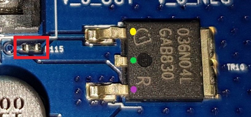
R40
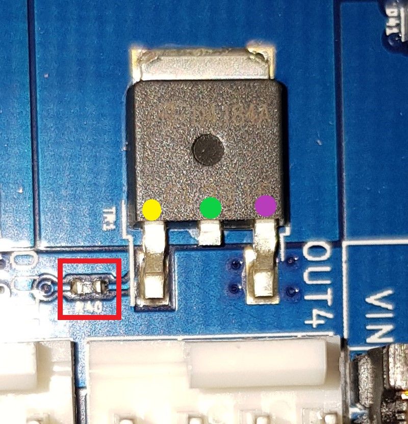
R57
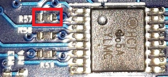
-
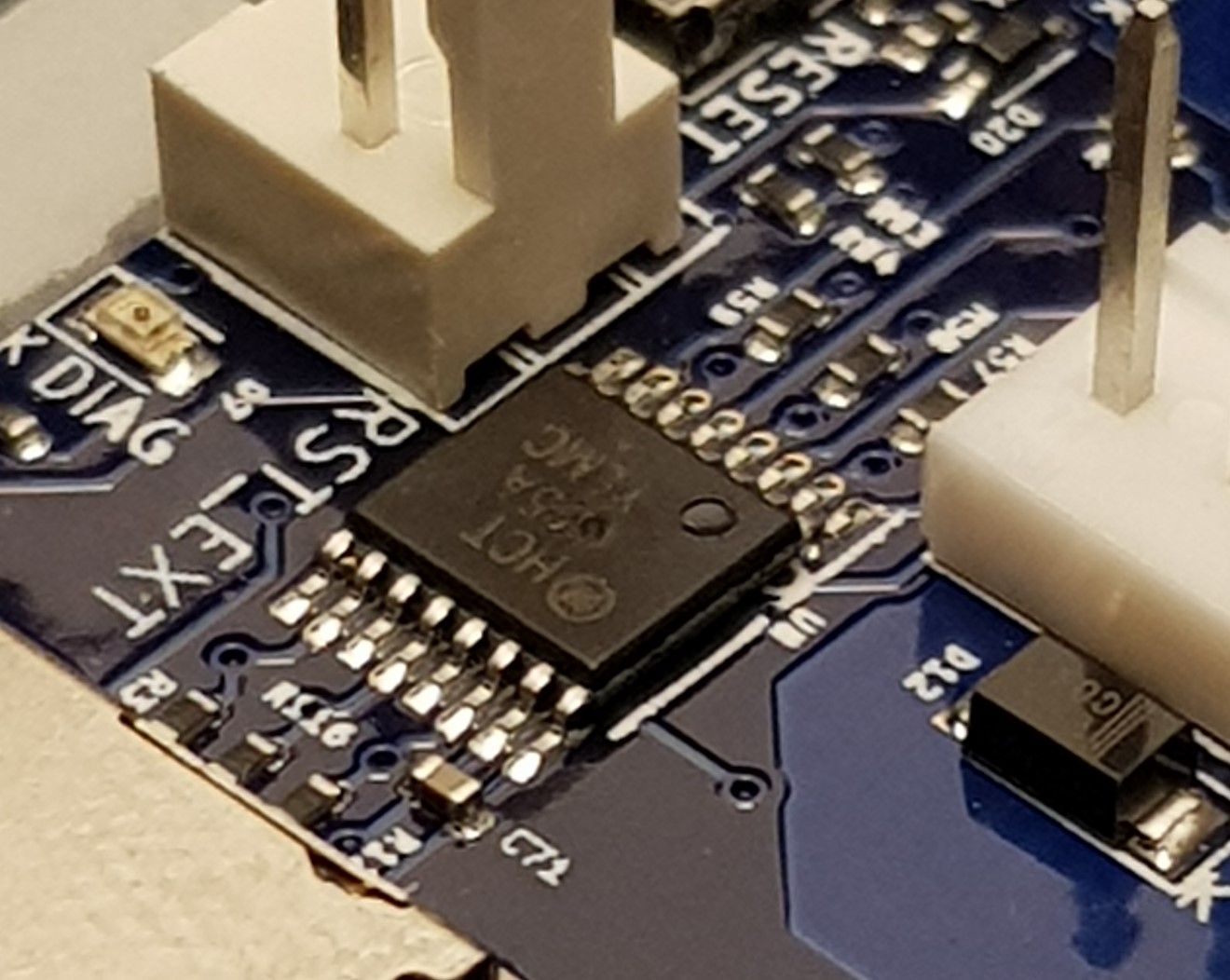
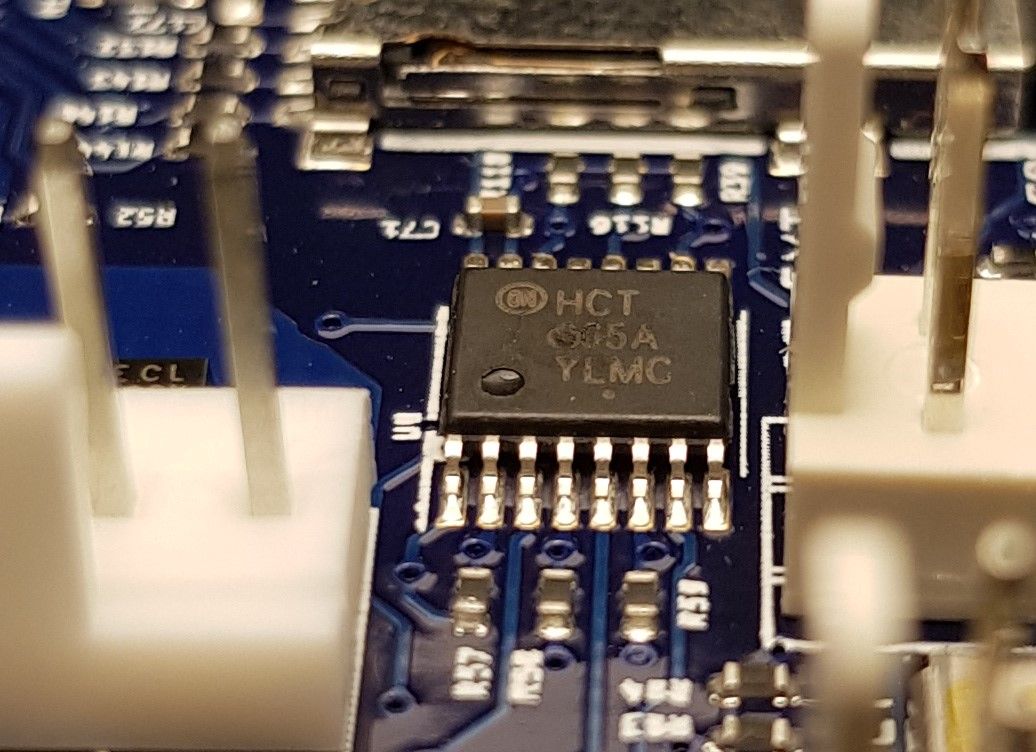
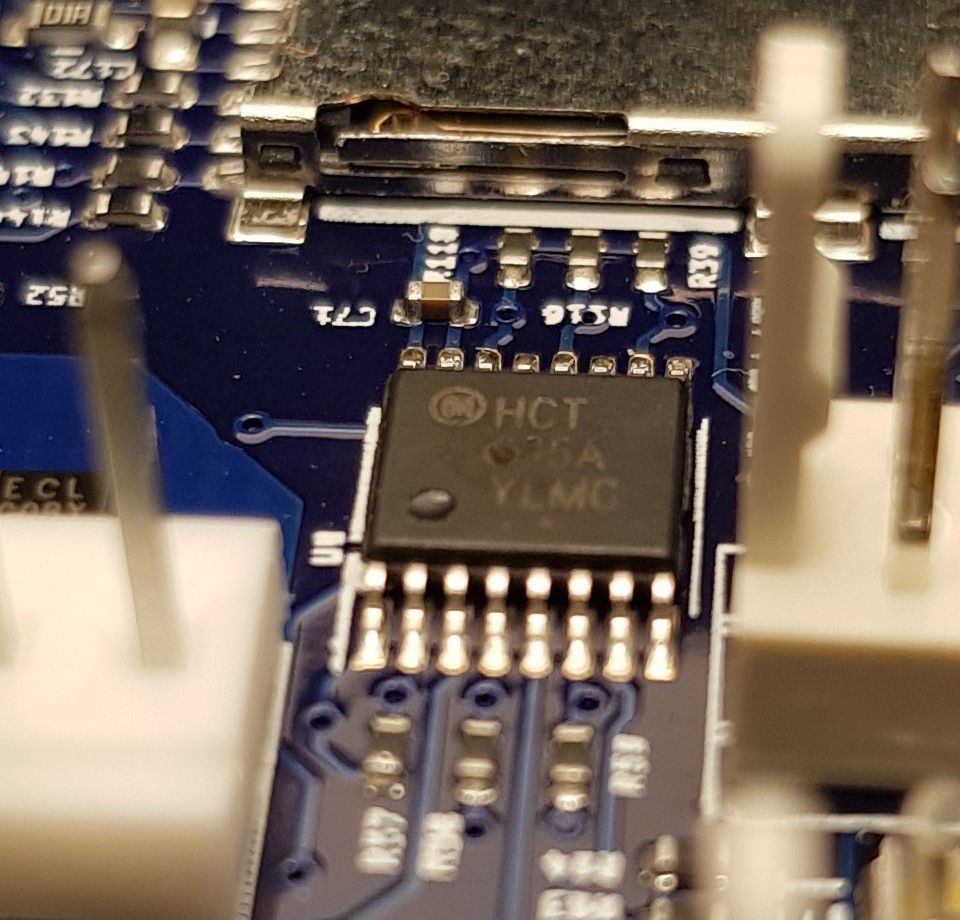
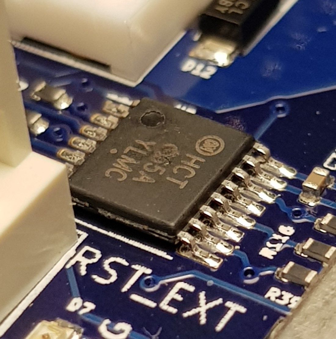
Does that chip next to R57 have a pock mark on it or is that just an artifact of the camera?
-
@phaedrux Thanks for pointing this out, I guess it comes with experience. I just had a look at it, there is something but I cannot say if it is a pock mark or a bulged. I will take a look at it tomorrow under daylight and post pictures.
Thank you.
-
@dc42 please take a look at the close up pictures of the 74HCT365 chip. Can this be the cause for the fault?
Could you please guide me where to place the test leads to measure voltage for R115, R40, R53 and R57. I posted location pictures for the components in my previous post.
Thank you.
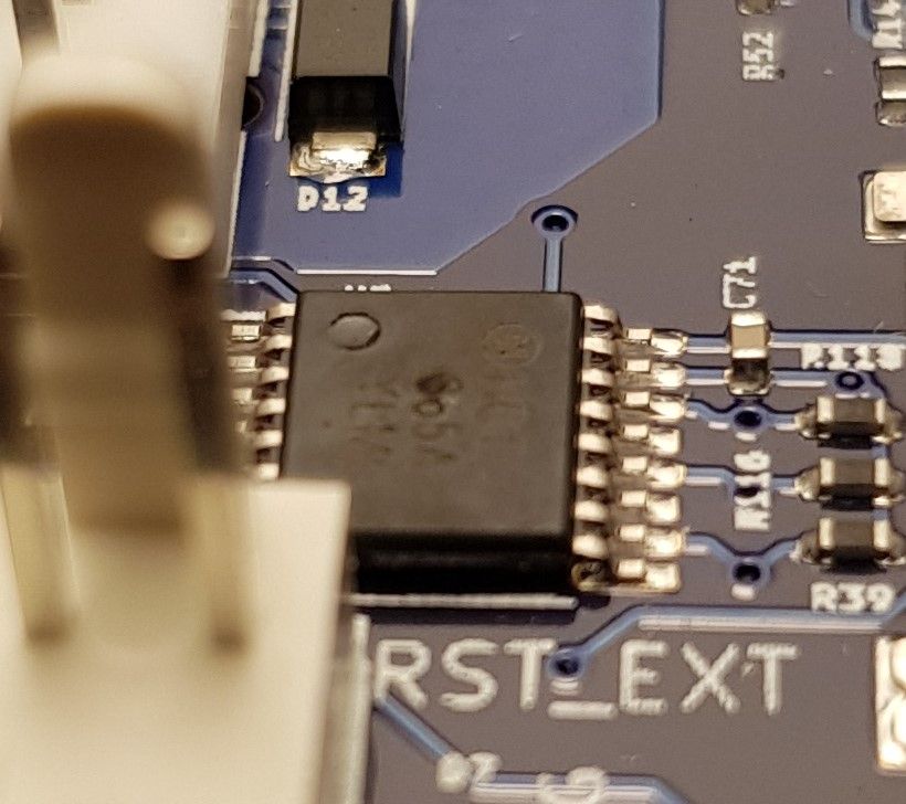
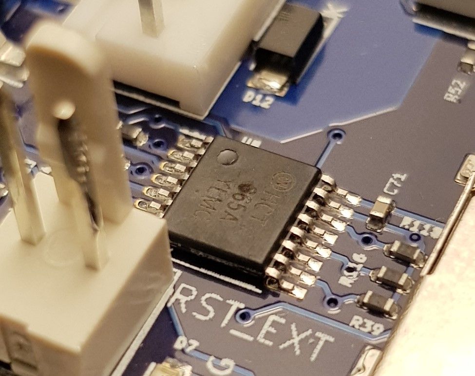
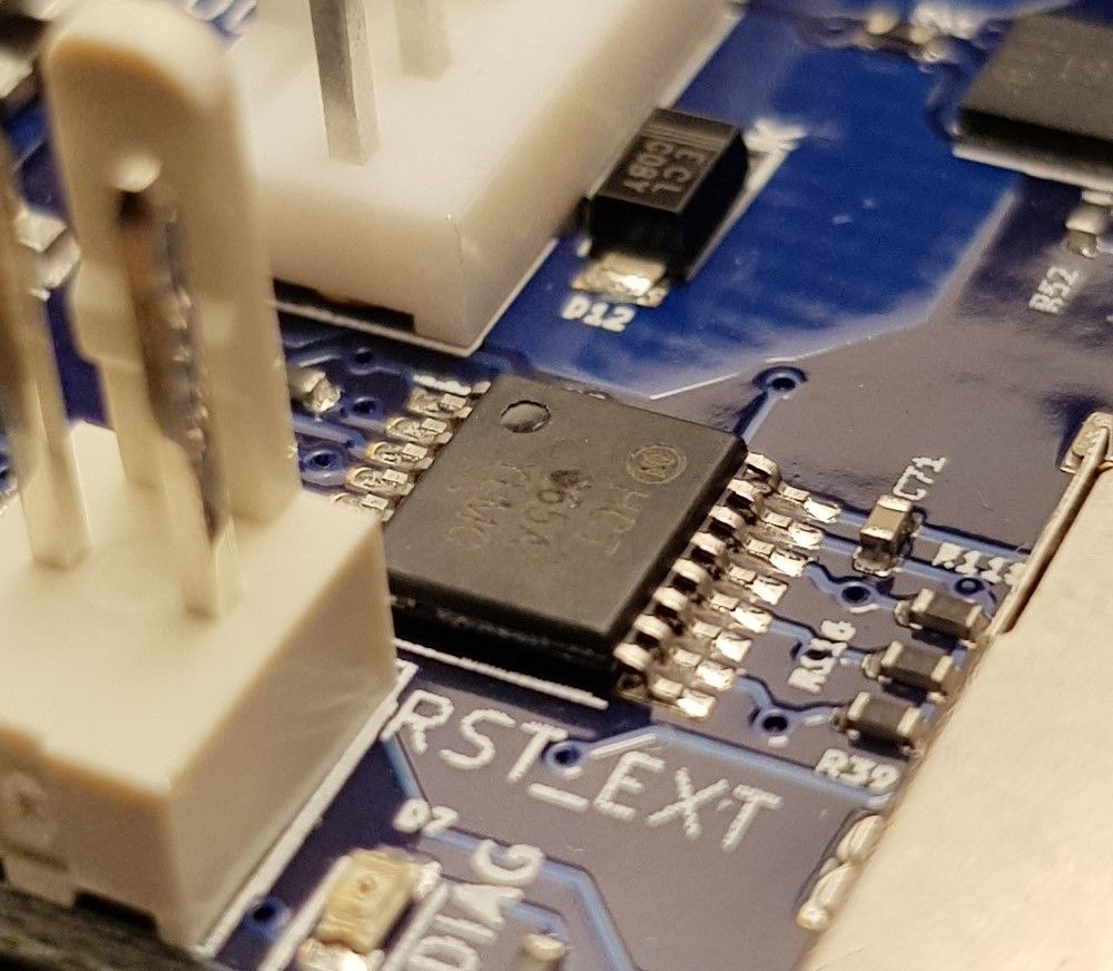
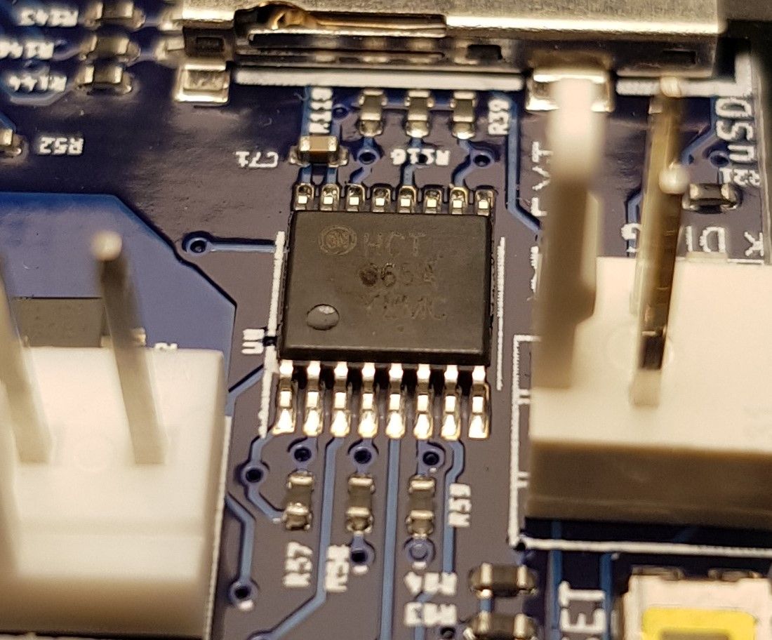
-
@kvi94 those pock marks look suspicious to me. I've Just examined three MB6HC boards, and on those boards I can read the figure 3 clearly at that location on the chip.
To measure the voltage that the driver is feeding to the mosfet, measure between one end of the mosfet gate resistor (e.g. R115) and ground.
-
@dc42 said in Heaters will not turn on:
To measure the voltage that the driver is feeding to the mosfet, measure between one end of the mosfet gate resistor (e.g. R115) and ground.
@dc42 As I will be doing this while it is powered via USB, using the input GND terminal is fine? Additionally, should I set the port active with a temperature and measure or measure at idle?