Smert effector tilting during bed leveling and print
-
I am experiencing some pretty intense tilting during printing and bed leveling seen here. Ignore the fan sticking up, I have to print another duct for it. I am using an Anycubic Predator with a Duet 2 Ethernet board and a Duet Smart Effector. Here is my config.g file:
; Configuration file for Duet WiFi (firmware version 3)
; executed by the firmware on start-up
;
; generated by RepRapFirmware Configuration Tool v3.1.4 on Mon Jul 20 2020 19:57:06 GMT-0500 (Central Daylight Time); General preferences
G90 ; send absolute coordinates...
M83 ; ...but relative extruder moves
M550 P"Anycubic Predator" ; set printer name
M665 R227 L440.45 B185 H410 ; Set delta radius, diagonal rod length, printable radius and homed height
M666 X0 Y0 Z0 ; put your endstop adjustments here, or let auto calibration find them; Network
M552 P192.168.86.37 S1 ; enable network and acquire dynamic address via DHCP
M586 P0 S1 ; enable HTTP
M586 P1 S0 ; disable FTP
M586 P2 S0 ; disable Telnet; Drives
M569 P0 S0 ; physical drive 0 goes forwards
M569 P1 S0 ; physical drive 1 goes forwards
M569 P2 S0 ; physical drive 2 goes forwards
M569 P3 S0 ; physical drive 3 goes forwards
M584 X0 Y1 Z2 E3 ; set drive mapping
M350 X16 Y16 Z16 E16 I1 ; configure microstepping with interpolation
M92 X80.00 Y80.00 Z80.00 E415.00 ; set steps per mm
M566 X1500.00 Y1500.00 Z1500.00 E1500.00 P1 ; set maximum instantaneous speed changes (mm/min)
M203 X18000.00 Y18000.00 Z18000.00 E10000.00 ; set maximum speeds (mm/min)
M201 X1500.00 Y1500.00 Z1500.00 E5000.00 ; set accelerations (mm/s^2)
M906 X1000 Y1000 Z1000 E1000 I30 ; set motor currents (mA) and motor idle factor in per cent
M84 S30 ; Set idle timeout; Retraction
M207 S1.9 F3000 Z0.388 ; Firmware retraction; Axis Limits
M208 Z0 S1 ; set minimum Z; Endstops
M574 X2 S1 P"xstop" ; configure active-high endstop for high end on X via pin xstop
M574 Y2 S1 P"ystop" ; configure active-high endstop for high end on Y via pin ystop
M574 Z2 S1 P"zstop" ; configure active-high endstop for high end on Z via pin zstop
M591 D0 P7 C"e0stop" L7 R50:200 E15 S1 ; filament sensor connected to e0_stop; Z-Probe
M558 P8 R0.4 C"zprobe.in+zprobe.mod" H10 F1200 T6000 ; set Z probe type to effector and the dive height + speeds
G31 P100 X0 Y0 Z.1 ; set Z probe trigger value, offset and trigger height
M557 R180 S20 ; define mesh grid; Heaters
M308 S0 P"bedtemp" Y"thermistor" T100000 B4138 ; configure sensor 0 as thermistor on pin bedtemp
M950 H0 C"bedheat" T0 ; create bed heater output on bedheat and map it to sensor 0
M307 H0 A137.8 C533.3 D1.5 V24.3 B0 ; disable bang-bang mode for the bed heater and set PWM limit
M140 H0 ; map heated bed to heater 0
M143 H0 S120 ; set temperature limit for heater 0 to 120C
M308 S1 P"e0temp" Y"pt1000" R4700 ; configure sensor 1 as PT1000 on pin e0temp
M950 H1 C"e0heat" T1 ; create nozzle heater output on e0heat and map it to sensor 1
M307 H1 B0 S1.00 ; disable bang-bang mode for heater and set PWM limit; Fans
M950 F1 C"fan1" Q500 ; create fan 1 on pin fan1 and set its frequency
M106 P1 S0 H-1 ; set fan 1 value. Thermostatic control is turned off; Tools
M563 P0 S"Hotend" D0 H1 F1 ; define tool 0
G10 P0 X0 Y0 Z0 ; set tool 0 axis offsets
G10 P0 R0 S0 ; set initial tool 0 active and standby temperatures to 0C; Custom settings are not defined
M572 D0 S0.2 ; pressure advance; Miscellaneous
M911 S10 R11 P"M913 X0 Y0 G91 M83 G1 Z3 E-5 F1000" ; set voltage thresholds and actions to run on power loss
M501 ; set the active parameters to those stored in sys/config-override.gand my bed.g file:
; bed.g
; called to perform automatic delta calibration via G32
;
; generated by RepRapFirmware Configuration Tool v3.1.4 on Mon Jul 20 2020 19:57:05 GMT-0500 (Central Daylight Time)
M561 ; clear any bed transform
G28 ; home all towers
G1 E-1.9 F300 ; retract a little
; Probe the bed at 6 peripheral and 6 halfway points, and perform 6-factor auto compensation
; Before running this, you should have set up your Z-probe trigger height to suit your build, in the G31 command in config.g.
G30 P0 X0 Y179.9 H0 Z-99999
G30 P1 X155.8 Y89.95 H0 Z-99999
G30 P2 X155.8 Y-89.95 H0 Z-99999
G30 P3 X0 Y-179.9 H0 Z-99999
G30 P4 X-155.8 Y-89.95 H0 Z-99999
G30 P5 X-155.8 Y89.95 H0 Z-99999
G30 P6 X0 Y89.9 H0 Z-99999
G30 P7 X77.86 Y44.95 H0 Z-99999
G30 P8 X77.86 Y-44.95 H0 Z-99999
G30 P9 X0 Y-89.9 H0 Z-99999
G30 P10 X-77.86 Y-44.95 H0 Z-99999
G30 P11 X-77.86 Y44.95 H0 Z-99999
G30 P12 X0 Y0 H0 Z-99999 S6
; Use S-1 for measurements only, without calculations. Use S4 for endstop heights and Z-height only. Use S6 for full 6 factors
; If your Z probe has significantly different trigger heights depending on XY position, adjust the H parameters in the G30 commands accordingly. The value of each H parameter should be (trigger height at that XY position) - (trigger height at centre of bed)
G29 ; grid mapand finally my config-overide.g file:
; config-override.g file generated in response to M500 at 2020-07-24 15:47
; This is a system-generated file - do not edit
; Delta parameters
;M665 L440.000:440.000:440.000 R226.608 H421.396 B185.0 X-0.123 Y0.106 Z0.000
;M666 X0.742 Y-0.494 Z-0.248 A0.00 B0.00
; Heater model parameters
M307 H0 A122.6 C715.7 D0.6 S1.00 V24.0 B0
M307 H1 A315.0 C177.6 D3.4 S1.00 V24.2 B0
; Workplace coordinates
G10 L2 P1 X0.00 Y0.00 Z0.00
G10 L2 P2 X0.00 Y0.00 Z0.00
G10 L2 P3 X0.00 Y0.00 Z0.00
G10 L2 P4 X0.00 Y0.00 Z0.00
G10 L2 P5 X0.00 Y0.00 Z0.00
G10 L2 P6 X0.00 Y0.00 Z0.00
G10 L2 P7 X0.00 Y0.00 Z0.00
G10 L2 P8 X0.00 Y0.00 Z0.00
G10 L2 P9 X0.00 Y0.00 Z0.00 -
@lildannyoso
A tilting effector is always a hardware/mechanical thing.
Beginning with equal rod length and tower angles/frame geometry. -
@lildannyoso I recognize that cooling arrangement

As @o_lampe says, it's always mechanical.
What rods do you have?
It's always worth giving everything a once over. Check where your rods attach, check the rollers, check that you haven't got belt stretch. Also make sure the nut on your hotend hasn't come loose. -
The distance between the rods must be the same at the top and the bottom of the rod (carriage side and effector side) for the parallelogram to be created.
Either the smart effector needs to be rotated 60 degrees, or your carriages are incompatible with the smart effector and you need to make an adaptor.
Does that help?
-
@lildannyoso
Looking at the video, you don't appear to be using the Smart Effector PCB adapters on the vertical rail carriages?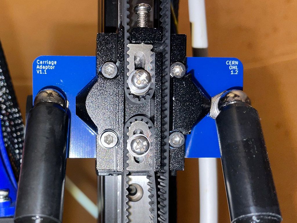
A delta printer mechanism relies on each pair of rods always being absolutely parallel.
If there is even the slightest difference, a fraction of a millimetre, in joint spacing between the two ends of the link arms/rods, the overall geometry of the machine will be wrong and the effector will tilt.
That's why you get the adapters in the kit, to guarantee correct spacing at both ends of the arms.
They can be on top of or sandwiched in a printed carriage, but those need to be what define the rod spacing.
-
Solved: One of my rods had come loose.