Final Step - Mesh Bed and Paneldue
-
First off, I have to say the amount of support and knowedge on here with the people actually working on developing this board and the software is astounding and I apprecieate that you guys put so much into your product.
I have hit every noob roadblock that a Professional Electrical Engineer can hit. lol Im in power so don't cast to much electronics shame on me. lol
Now the issues standing in front of my first print on this machine.
_________________________________________________________________________________________________________;- Sub problem: (if you cant fix the main problem please help with this, but skip for now)
Paneldue: Not so much preventing me but it doesnt work right, I get it to boot and connect sometimes but then doesnt show any real data. I tried to reformat my SD to 512 sectors but my mac doesnt like being that usable and cant figure out a tool that will do it. I have parallels running windows 11 and for some reason im having trouble getting the drive to be recognized in there after I formatted it in mac as FAT32(mac only allows 4k setcor for that format "Disk Utility" tool. (UPDATE: also while PID tuning my Hot end somehow now the paneldue doesnt even boot up with a splash screen)
_________________________________________________________________________________________________________;
Main Problem:: My bed offsets are not super great so im going to walk you through what I did to try and get my full range of motion and to be able to print where I say it should print.
I want to do center of the bed as 0,0. I will provide a graphic here showing my range of motion and where things are at endstops. I measured with calipers and I also used the DRO on DWC to measure.
-
First I homed all, got to X Y endstops and then lowered the nozzle to where it would be touching the bed.(off the bed due to being at X,Y endstops.
-
Then, I (to get the DRO to read right) sent the below command to get my zero to make subsequent movements useful in the readout. ( if ever hearing a click when I hit endstops like a skipped step I rehomed and rezeroed becaues I noticed it will allow me to go past the endstops in esteps count sense which moves my whole offset.
G92 X0 Y0 Z0
- Finally, I moved back up and over to where the nozzle touched the corner of the bed and repeated for the Probe. Both measurements were with the full diameter of the nozzle and probe in the limits of the bed so not to miss or clip the side when probing later.(so probable 2-3mm in from actual 0,0)
-
-
- The readout when the Nozzle was at Left Bottom corner:
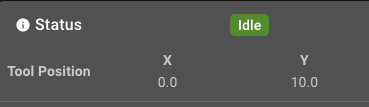

- The readout when the Nozzle was at Left Bottom corner:
-
-
-
- The readout when the Probe was at Left Bottom corner:

- The readout when the Probe was at Left Bottom corner:
-
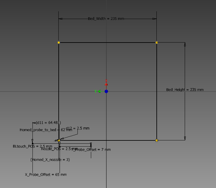
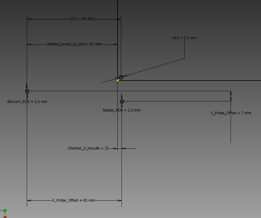
With a bunch of fiddling I think I have a good drawing of what the bed is like at home. NOW look at that first and then tell me why my offsets arent working. This is mainly due to my lack of understanding of how th offset system work in the Duet but I digress, I still need help. Getting just one print that is semi ok would be all the assistance I need then im going to not touch it short of pressure advance and Esteps.
Anyway, heres the layout:
Main Goal: Get this sucker to get me a mesh that gets pretty close to hitting the full extents of the bed. At the moment it probes about 2/3 of the bed. with I think these two parts making up the probing setup and I have tried other dimensions here just not sure I know what im doing. I forget if this one actually works but I have been able to get it to probe and some just dont work. I think rn im getting a no valid mesh error. not looking to fix that I just think I have the base understand of this wrong so some sort of help coming from where I am here with these measurements would be ideal.
; Z-Probe
* M950 S0 C"io3.out"                                    ; create servo pin 0 for BLTouch
* M558 P9 C"io3.in" H5 F600 T6000                       ; set Z probe type to bltouch and the dive height + speeds
* G31 P500 X-64 Y-10 Z2.5                                ; set Z probe trigger value, offset and trigger height
* M557 X0:235 Y0:235 S5                                 ; define mesh grid
*
* ; Heaters
* M308 S0 P"temp0" Y"thermistor" T98801 B4185           ; configure sensor 0 as thermistor on pin temp0
* M950 H0 C"out0" T0                                    ; create bed heater output on out0 and map it to sensor 0
* M307 H0 B0 S1.00                                      ; disable bang-bang mode for the bed heater and set PWM limit
* M140 H0                                               ; map heated bed to heater 0
* M143 H0 S110                                          ; set temperature limit for heater 0 to 110C
* M308 S1 P"temp1" Y"thermistor" T98801 B4725 C7.06e-8 ; configure sensor 1 as thermistor on pin temp1
* M950 H1 C"out1" T1                                    ; create nozzle heater output on out1 and map it to sensor 1
* M307 H1 B0 S1.00                                      ; disable bang-bang mode for heater  and set PWM limit
* M143 H1 S300                                          ; set temperature limit for heater 1 to 300C
*
* ; Fans
* M950 F0 C"out3" Q50                                   ; create fan 0 on pin out3 and set its frequency
* M106 P0 C"PartCool" S0 H-1                            ; set fan 0 name and value. Thermostatic control is turned off
* M950 F1 C"out4" Q500                                  ; create fan 1 on pin out4 and set its frequency
* M106 P1 C"HotEnd" S1 H1 T60                           ; set fan 1 name and value. Thermostatic control is turned on
* M950 F2 C"out5" Q500                                  ; create fan 2 on pin out5 and set its frequency
* M106 P2 C"CaseFan" S1 H1:0 T60                        ; set fan 2 name and value. Thermostatic control is turned on
*
* ; Tools
* M563 P0 S"HotEnd" D0 H1 F0                            ; define tool 0
* G10 P0 X0 Y-13 Z0                                     ; set tool 0 axis offsets
* G10 P0 R0 S0                                          ; set initial tool 0 active and standby temperatures to 0C
*
* ; Custom settings are not defined
*
* ; Miscellaneous
* M501                                                  ; load saved parameters from non-volatile memory
* M911 S10 R11 P"M913 X0 Y0 G91 M83 G1 Z3 E-5 F1000"    ; set voltage thresholds and actions to run on power loss
* T0                                                    ; select first tool
* M575 P0 S1 B57600                                    ; enable support for PanelDue
*
the Nozzle_POS is its position when homes(the 2.5 is just a caliper measurement of the d of the end of the nozzle and same for the Probe.) Homed_Probe/Nozz. are the measurements when all axes are homed.
I think im struggling on where to put what offset. I started with just having the probe offset and then I put some tool offsets and it seems like there are more offsets than I can keep track of to make this not do bad stuff.
- Sub problem: (if you cant fix the main problem please help with this, but skip for now)
-
Can you post your full config?
Does your actual config.g contain all those asterix?
*The offset for the XY axis to define the bed size is defined in M208 but your config.g snip doesn't include that.
Have you seen this page? https://duet3d.dozuki.com/Wiki/Centering_the_bed_or_setting_the_bed_origin
It may be easier to start with the 0,0 origin in the front left corner rather than the center. Then you can set the M208 minimum point as where the endstop triggers.
Example, if the endstops are on the low end of travel they may be a negative distance away from the edge of the bed, so your M208 minimum would be negative. It gets a little trickier when the ensstops are on the high end of travel. But your config snip doesn't include endstop config either so I'm not sure where they are located.
I should also mention that it is important to establish the correct axis orientation such that -x is moving to the left, +x is moving to the right, -y is moving to the front, +y moves to the back. All offsets will be based on this assumption of basic cartesian space.
The probe offset itself helps the firmware know where the mesh is in relation to the nozzle, but your mesh size will still need to be defined with that offset in mind if you want to make the most of the reachable area. The firmware will simply skip the mesh area that it can't physically reach.
I'm not sure what to say about your paneldue problem. Which SD card are you talking about formatting? The best tool to use for formatting is this: https://www.sdcard.org/downloads/formatter/ It will format based on what the card was designed to use and don't worry about it beyond that.
You don't mention what firmware version you are using but your config snip looks like RRF3.x at least. You need to enable the paneldue in the config and the Paneldue will need to have updated firmware to work properly. I would suggest that you should be using firmware 3.3 for both.
It would help if you could provide us with your full config.g, homing files, bed.g any other macros you use for setup. And the results of sending M122 and M98 P"config.g". That would give us a better idea of the state of your machine.
-
 undefined Phaedrux moved this topic from My Duet controlled machine
-
@phaedrux
So finally getting back to working on this. No those asterix are not in my config.
Also Here is my full config.
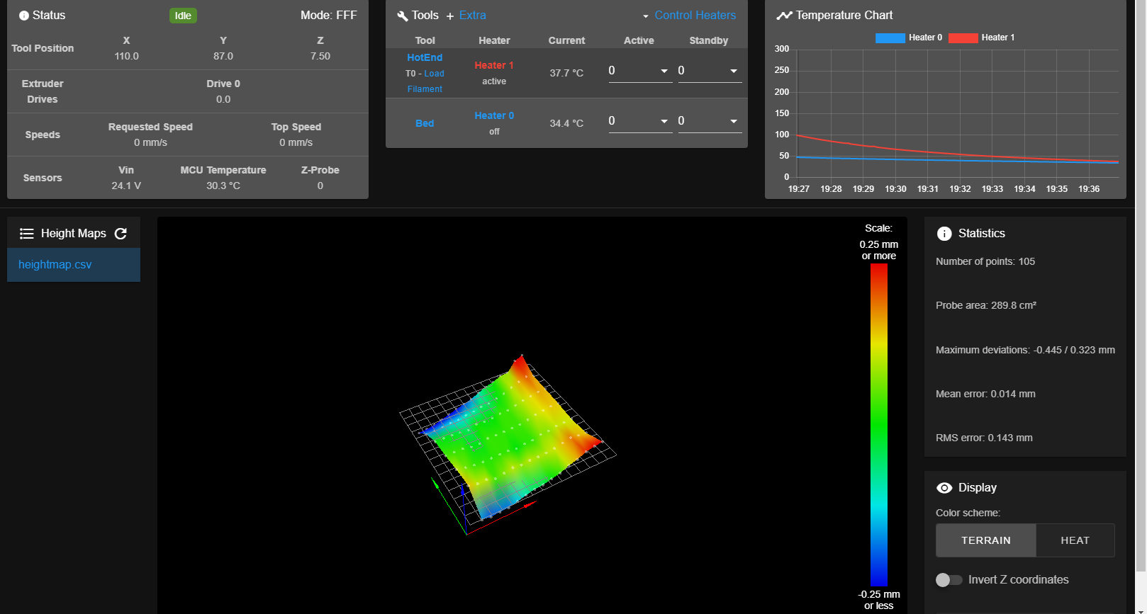
And, i ran the mesh on a area of X -115:115 Y-115:115 inc. 11.5 (using the gui to define the grid to probe)
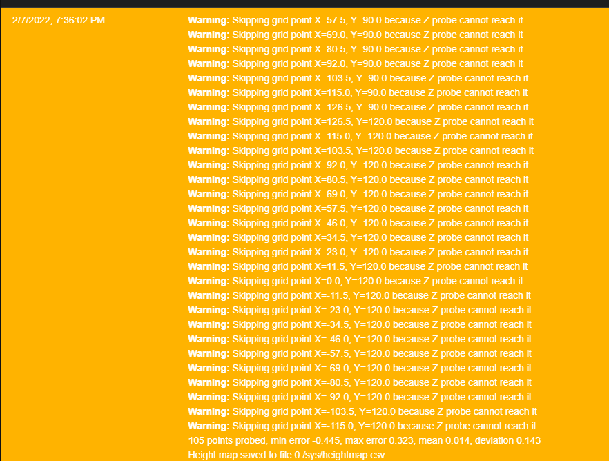
the probe went off the bed for the whole first row in the fron so -115Y is off bed.so i edited it the grid to X -115:115 Y-90:140 inc.11.5x & 23y and it didnt go off the bed but it skipps alot of points and i get this in the console.
; Configuration file for Duet 3 Mini 5+ (firmware version 3.3) ; executed by the firmware on start-up ; ; generated by RepRapFirmware Configuration Tool v3.3.10 on Thu Jan 27 2022 23:10:21 GMT-0600 (Central Standard Time) ; General preferences G90 ; send absolute coordinates... M83 ; ...but relative extruder moves M550 P"Enduet 3VED" ; set printer name ; Network M552 S1 ; enable network M586 P0 S1 ; enable HTTP M586 P1 S0 ; disable FTP M586 P2 S0 ; disable Telnet ; Drives M569 P0.0 S0 ; physical drive 0.0 goes backwards M569 P0.1 S0 ; physical drive 0.1 goes backwards M569 P0.2 S1 ; physical drive 0.2 goes forwards M569 P0.3 S0 ; physical drive 0.3 goes backwards M584 X0.0 Y0.1 Z0.2 E0.3 ; set drive mapping M350 X16 Y16 Z16 E16 I1 ; configure microstepping with interpolation M92 X80.00 Y80.00 Z397.50 E409.00 ; set steps per mm M566 X900.00 Y900.00 Z60.00 E300.00 ; set maximum instantaneous speed changes (mm/min) M203 X9000.00 Y9000.00 Z300.00 E6000.00 ; set maximum speeds (mm/min) M201 X500.00 Y500.00 Z100.00 E6000.00 ; set accelerations (mm/s^2) M906 X700 Y700 Z700 E1200 I30 ; set motor currents (mA) and motor idle factor in per cent M84 S30 ; Set idle timeout ; Axis Limits M208 X-115:115 Y-115:115 ; set axis minima ;M208 X235 Y235 Z250 S0 ; set axis maxima ; Endstops M574 X1 S1 P"io0.in" ; configure switch-type (e.g. microswitch) endstop for low end on X via pin io0.in M574 Y1 S1 P"io1.in" ; configure switch-type (e.g. microswitch) endstop for low end on Y via pin io1.in M574 Z1 S2 ; configure Z-probe endstop for low end on Z ; Z-Probe M950 S0 C"io3.out" ; create servo pin 0 for BLTouch M558 P9 C"io3.in" H5 F600 T6000 ; set Z probe type to bltouch and the dive height + speeds G31 P500 X-64 Y-10 Z2.5 ; set Z probe trigger value, offset and trigger height M557 X-115:115 Y-115:115 S5 ; define mesh grid ; Heaters M308 S0 P"temp0" Y"thermistor" T98801 B4185 ; configure sensor 0 as thermistor on pin temp0 M950 H0 C"out0" T0 ; create bed heater output on out0 and map it to sensor 0 M307 H0 B0 S1.00 ; disable bang-bang mode for the bed heater and set PWM limit M140 H0 ; map heated bed to heater 0 M143 H0 S110 ; set temperature limit for heater 0 to 110C M308 S1 P"temp1" Y"thermistor" T98801 B4725 C7.06e-8 ; configure sensor 1 as thermistor on pin temp1 M950 H1 C"out1" T1 ; create nozzle heater output on out1 and map it to sensor 1 M307 H1 B0 S1.00 ; disable bang-bang mode for heater and set PWM limit M143 H1 S300 ; set temperature limit for heater 1 to 300C ; Fans M950 F0 C"out3" Q50 ; create fan 0 on pin out3 and set its frequency M106 P0 C"PartCool" S0 H-1 ; set fan 0 name and value. Thermostatic control is turned off M950 F1 C"out4" Q500 ; create fan 1 on pin out4 and set its frequency M106 P1 C"HotEnd" S1 H1 T60 ; set fan 1 name and value. Thermostatic control is turned on M950 F2 C"out5" Q500 ; create fan 2 on pin out5 and set its frequency M106 P2 C"CaseFan" S1 H-1 ; set fan 2 name and value. Thermostatic control is turned on ; Tools M563 P0 S"HotEnd" D0 H1 F0 ; define tool 0 G10 P0 X0 Y-13 Z0 ; set tool 0 axis offsets G10 P0 R0 S0 ; set initial tool 0 active and standby temperatures to 0C ; Custom settings are not defined ; Miscellaneous M501 ; load saved parameters from non-volatile memory M911 S10 R11 P"M913 X0 Y0 G91 M83 G1 Z3 E-5 F1000" ; set voltage thresholds and actions to run on power loss T0 ; select first tool ;M575 P0 S1 B57600 ; enable support for PanelDue M552 S1``` -
Forgot the M112 and M98
	M98 P"config.g"
HTTP is enabled on port 80
FTP is disabled
TELNET is disabled
Error: bad grid definition: Too many grid points; suggest increase spacing to 11.5mm
Warning: Heater 1 appears to be over-powered. If left on at full power, its temperature is predicted to reach 543C
2/7/2022, 7:55:30 PM M122 === Diagnostics === RepRapFirmware for Duet 3 Mini 5+ version 3.3 (2021-06-15 21:46:11) running on Duet 3 Mini5plus WiFi (standalone mode) Board ID: V1NGY-M396U-D65J0-40KMS-LW03Z-7Z8RQ Used output buffers: 3 of 40 (22 max) === RTOS === Static ram: 102724 Dynamic ram: 106432 of which 0 recycled Never used RAM 34548, free system stack 132 words Tasks: NETWORK(ready,15.8%,226) HEAT(notifyWait,0.0%,366) Move(notifyWait,0.1%,305) CanReceiv(notifyWait,0.0%,941) CanSender(notifyWait,0.0%,357) CanClock(delaying,0.0%,340) TMC(notifyWait,0.7%,115) MAIN(running,82.6%,412) IDLE(ready,0.1%,29) AIN(delaying,0.8%,264), total 100.0% Owned mutexes: WiFi(NETWORK) HTTP(MAIN) === Platform === Last reset 00:26:13 ago, cause: power up Last software reset at 2022-02-07 18:28, reason: User, GCodes spinning, available RAM 31340, slot 2 Software reset code 0x0003 HFSR 0x00000000 CFSR 0x00000000 ICSR 0x00000000 BFAR 0xe000ed38 SP 0x00000000 Task MAIN Freestk 0 n/a Error status: 0x00 MCU revision 3, ADC conversions started 1573413, completed 1573411, timed out 0, errs 0 Step timer max interval 1335 MCU temperature: min 28.3, current 28.8, max 30.8 Supply voltage: min 24.0, current 24.1, max 24.2, under voltage events: 0, over voltage events: 0, power good: yes Heap OK, handles allocated/used 0/0, heap memory allocated/used/recyclable 0/0/0, gc cycles 0 Driver 0: position 8800, standstill, SG min/max 0/14, read errors 0, write errors 0, ifcnt 14, reads 17236, writes 14, timeouts 0, DMA errors 0 Driver 1: position 8000, standstill, SG min/max 0/20, read errors 0, write errors 0, ifcnt 14, reads 17236, writes 14, timeouts 0, DMA errors 0 Driver 2: position 2981, standstill, SG min/max 0/2, read errors 0, write errors 0, ifcnt 14, reads 17235, writes 14, timeouts 0, DMA errors 0 Driver 3: position 0, standstill, SG min/max 0/0, read errors 0, write errors 0, ifcnt 9, reads 17240, writes 9, timeouts 0, DMA errors 0 Driver 4: position 0, standstill, SG min/max 0/0, read errors 0, write errors 0, ifcnt 9, reads 17241, writes 9, timeouts 0, DMA errors 0 Driver 5: position 0, assumed not present Driver 6: position 0, assumed not present Date/time: 2022-02-07 19:55:28 Cache data hit count 2898403244 Slowest loop: 32.96ms; fastest: 0.11ms === Storage === Free file entries: 10 SD card 0 detected, interface speed: 22.5MBytes/sec SD card longest read time 3.9ms, write time 2.1ms, max retries 0 === Move === DMs created 83, maxWait 99849ms, bed compensation in use: mesh, comp offset 0.000 === MainDDARing === Scheduled moves 322, completed moves 322, hiccups 0, stepErrors 0, LaErrors 0, Underruns [0, 0, 0], CDDA state -1 === AuxDDARing === Scheduled moves 0, completed moves 0, hiccups 0, stepErrors 0, LaErrors 0, Underruns [0, 0, 0], CDDA state -1 === Heat === Bed heaters = 0 -1, chamberHeaters = -1 -1 Heater 1 is on, I-accum = 0.0 === GCodes === Segments left: 0 Movement lock held by null HTTP is ready with "M122 " in state(s) 0 Telnet is idle in state(s) 0 File is idle in state(s) 0 USB is idle in state(s) 0 Aux is idle in state(s) 0 Trigger is idle in state(s) 0 Queue is idle in state(s) 0 LCD is idle in state(s) 0 SBC is idle in state(s) 0 Daemon is idle in state(s) 0 Aux2 is idle in state(s) 0 Autopause is idle in state(s) 0 Code queue is empty. === CAN === Messages queued 14266, received 0, lost 0, longest wait 0ms for reply type 0, peak Tx sync delay 0, free buffers 17 (min 17), ts 7867/0/0 Tx timeouts 0,107,7866,0,0,6290 last cancelled message type 30 dest 127 === Network === Slowest loop: 21.59ms; fastest: 0.00ms Responder states: HTTP(0) HTTP(0) HTTP(0) HTTP(0) FTP(0) Telnet(0), 0 sessions HTTP sessions: 1 of 8 - WiFi - Network state is active WiFi module is connected to access point Failed messages: pending 0, notready 0, noresp 0 WiFi firmware version 1.26 WiFi MAC address d8:bf:c0:14:e6:34 WiFi Vcc 3.38, reset reason Power up WiFi flash size 2097152, free heap 25120 WiFi IP address 192.168.0.27 WiFi signal strength -45dBm, mode 802.11n, reconnections 0, sleep mode modem Clock register 00002002 Socket states: 0 0 0 0 0 0 0 0 -
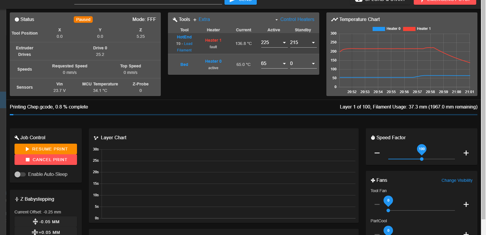
In the middle of this i tried to see if i can print even with the bad offsets and it starts to print but about halfway into the first layer i get a heater fault and then it stops. So now theres another issue


When it says fault both the active and standby temps in DWC are set to my preheat temp. not sure if thats supposed to be like that or not.
-
For the grid point skipping that will happen when the probe can't reach the point you've set it to probe.
You'll need to set the grid size taking into account the offsets of the probe.
For starters though you should verify that you can actually reach the extents of travel you've defined with M208. With the nozzle at 0,0 which should be the center of the bed, can you actually move 115mm in every direction from there?
Have you measured the distance of the probe from the nozzle accurately?
For the heaters, they likely just need to have a tuning cycle.
https://duet3d.dozuki.com/Wiki/Tuning_the_heater_temperature_control