Duet3D Logo Duet3D
    • Tags
    • Documentation
    • Order
    • Register
    • Login

    MFM recurring error

    Scheduled Pinned Locked Moved
    Filament Monitor
    5
    25
    1.1k
    Loading More Posts
    • Oldest to Newest
    • Newest to Oldest
    • Most Votes
    Reply
    • Reply as topic
    Log in to reply
    This topic has been deleted. Only users with topic management privileges can see it.
    • infiniteloopundefined
      infiniteloop @wouldstain
      last edited by

      @wouldstain Electrically, your MFM looks fine. I can imagine a mechanical reason for the "drop-outs" you encounter: maybe the magnet does not always rotate? One possible reason is a "hanging" idler - tolerances of the design are a bit narrow for FFM printers. In my case, some filing on the two idler parts, especially to clear the path of the bearing, made the MFM go smooth.

      wouldstainundefined 1 Reply Last reply Reply Quote 0
      • Surgikillundefined
        Surgikill @alankilian
        last edited by

        @alankilian Thanks for this. I've been having issues. My agc is 63 also. The center bearing was rubbing on the sensor. Hopefully it's not destroyed, there was a pretty nice ring rubbed into it.

        1 Reply Last reply Reply Quote 0
        • wouldstainundefined
          wouldstain @infiniteloop
          last edited by

          @infiniteloop I actually marked the idler so I can see it moving. Also.. when I put it together I did some filing to makes sure stuff was moving freely. I can pull filament through it manually and it feels like it moves smoothly.

          infiniteloopundefined 1 Reply Last reply Reply Quote 0
          • wouldstainundefined
            wouldstain @alankilian
            last edited by

            @alankilian I had not looked at distance between sensor and magnet as a possibility. Any suggestions on what the distance should be?

            alankilianundefined 1 Reply Last reply Reply Quote 0
            • alankilianundefined
              alankilian @wouldstain
              last edited by alankilian

              @wouldstain THIS page says the target distance is 0.25mm and that the AGC should be between 50 and 105 so your AGC is not out-of-range, just on the low-side of the range.

              Since you're getting excellent above-desired reading of 104% to 116% and you're getting 0% minimum it seemed to be that your magnet was getting stuck and not turning.

              So take a look and see if you see any marks on the top of the sensor and if so, add a sheet of paper or two to the case and see if your AGC gets larger and if it works better.

              (My AGC is 123 which is out-of-range high, but it seems to work so I'm not going to fiddle with it.)

              SeemeCNC Rostock Max V3 converted to V3.2 with a Duet2 Ethernet Firmware 3.2 and SE300

              wouldstainundefined Surgikillundefined 2 Replies Last reply Reply Quote 0
              • wouldstainundefined
                wouldstain @alankilian
                last edited by

                @alankilian Thank you!
                I'll definitely give that a try later!

                1 Reply Last reply Reply Quote 0
                • Surgikillundefined
                  Surgikill @alankilian
                  last edited by

                  @alankilian Do you know of any reason the AGC would climb during a print? I took some plastic sheet and shimmed the monitor. My AGC started at 75, and I have been pulling the states throughout the print, and now it has climbed to 90. I also have had 2 false "Too little movement" on a 45 minute print so far, so it doesn't seem to have fixed anything.

                  alankilianundefined 1 Reply Last reply Reply Quote 0
                  • alankilianundefined
                    alankilian @Surgikill
                    last edited by

                    @surgikill

                    Rats, it was worth a shot anyway.

                    The AGC would go up if the space between the magnet and sensor was increasing. Maybe your paper is springing-back somehow?

                    Anyway, I'm sorry it didn't help.

                    I think one of the duet gang can jump on and see if they have any further suggestions.

                    SeemeCNC Rostock Max V3 converted to V3.2 with a Duet2 Ethernet Firmware 3.2 and SE300

                    1 Reply Last reply Reply Quote 1
                    • infiniteloopundefined
                      infiniteloop @wouldstain
                      last edited by

                      @wouldstain Let's look further. In my setup, the filament can go into the MFM with an angle - if it was too much bent, I got false readings, especially with stiff filaments. If you can exclude mechanical problems, you might want to check print moves at a higher distance (currently, you stick with the recommended 3 mm). Try 5-10 mm instead.

                      Finally, there is a hot debate about the usefulness of adding a capacitor to the power lines of the MFM, you can look it up here. But I think this will only help in case of unstable supply voltage.

                      One last question: where do you locate your MFM, and how fix is the distance between it and the extruder?

                      wouldstainundefined 1 Reply Last reply Reply Quote 1
                      • wouldstainundefined
                        wouldstain @alankilian
                        last edited by

                        @alankilian gapped with some paper as suggested.
                        Same issue:
                        m591 d0
                        Duet3D rotating magnet filament monitor v3 on pin e0stop, enabled, sensitivity 25.63mm/rev, allow 1% to 200%, check printing moves every 3.0mm, version 3, mag 131 agc 74, measured sensitivity 33.09mm/rev, min 1% max 132% over 61.4mm

                        alankilianundefined 1 Reply Last reply Reply Quote 0
                        • alankilianundefined
                          alankilian @wouldstain
                          last edited by

                          @wouldstain

                          Bummer!!!

                          As an experiment and even though it's wasteful, maybe helpful.

                          Try:

                          • Raising the extruder temp a LOT. 15C or so.
                          • Moving the extruder 20mm away from the bed.
                          • Run your print.

                          You'll be making spaghetti, but this will demonstrate if the extruder is clogging or if there's some interaction between the extruder and the print that's jamming the filament.

                          If it "prints" without an under-length move we'll figure out more experiments.

                          SeemeCNC Rostock Max V3 converted to V3.2 with a Duet2 Ethernet Firmware 3.2 and SE300

                          wouldstainundefined 1 Reply Last reply Reply Quote 0
                          • Phaedruxundefined
                            Phaedrux Moderator
                            last edited by

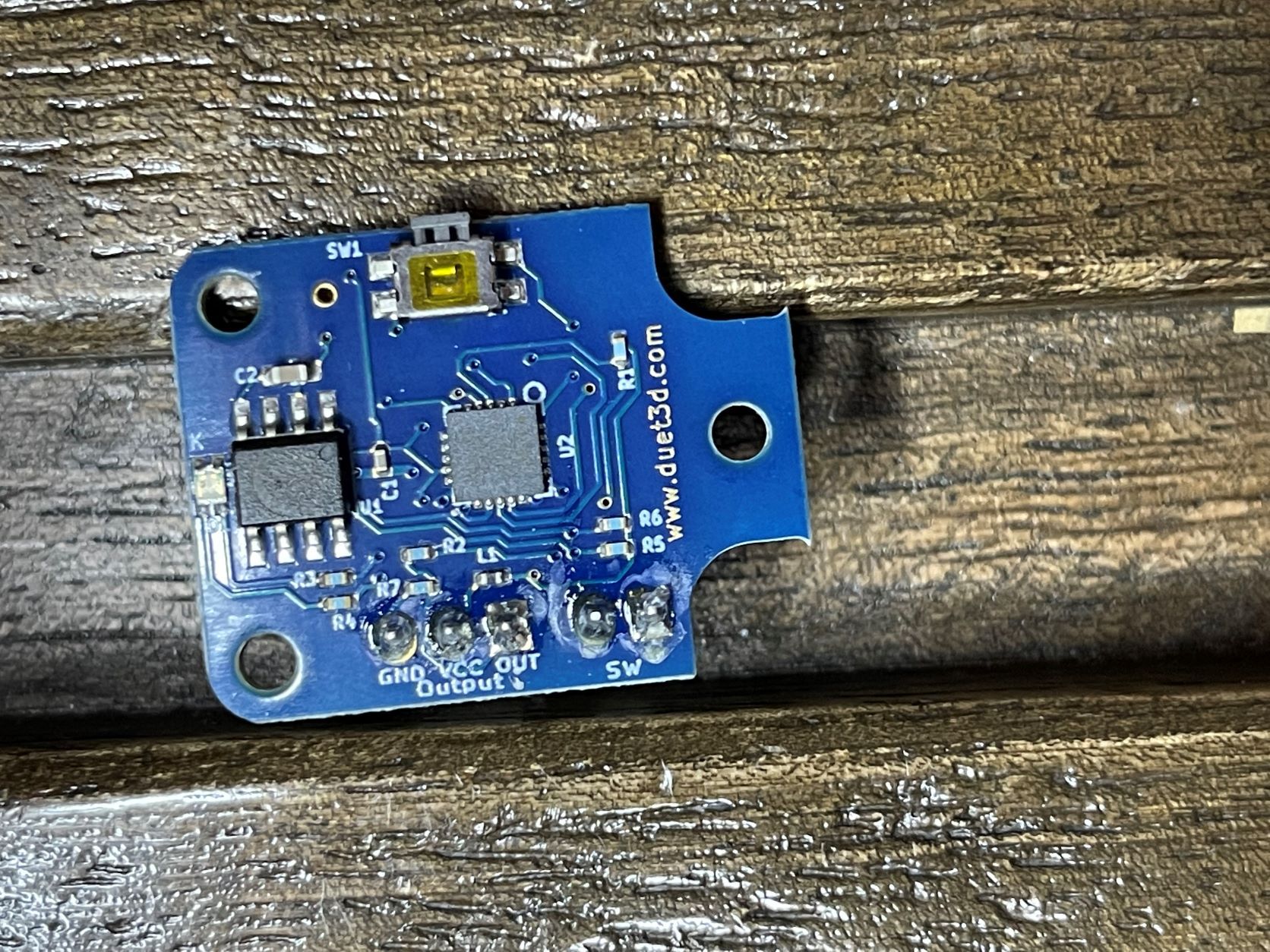
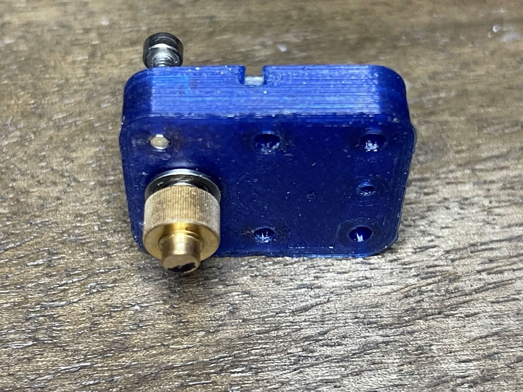
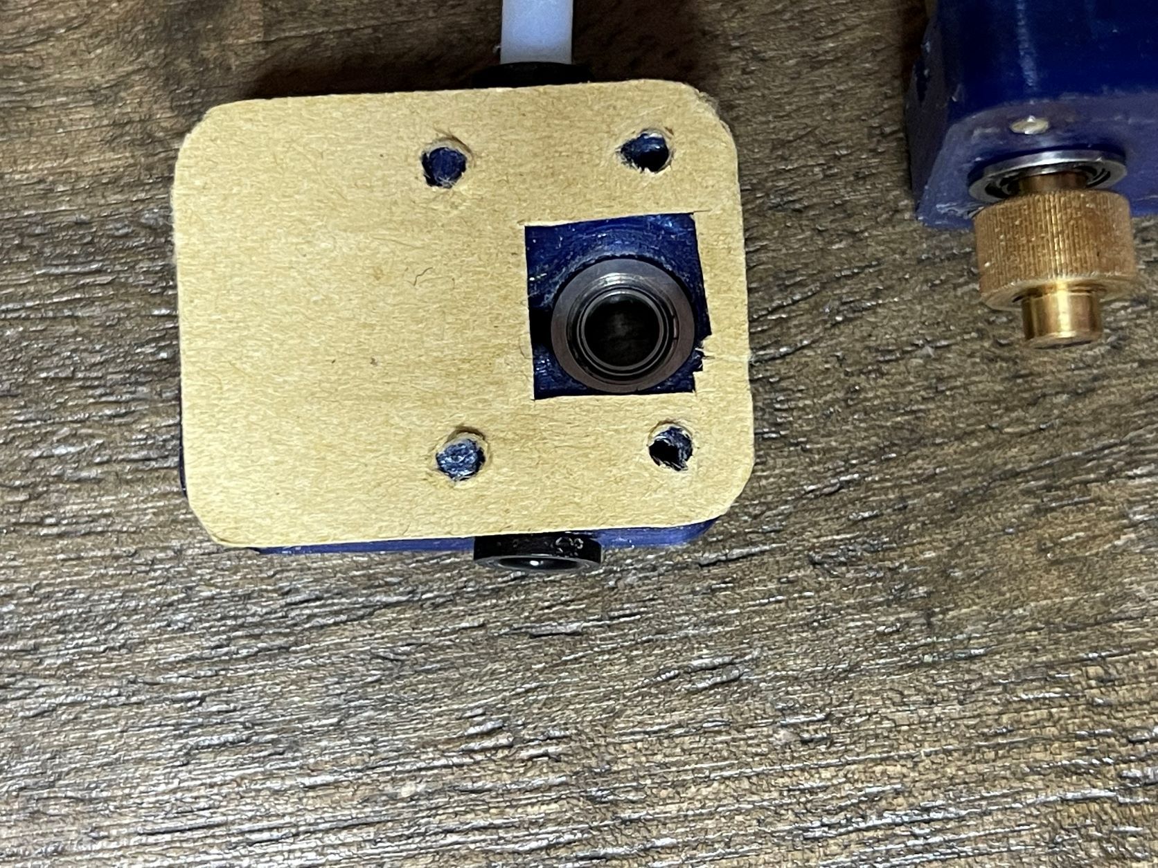
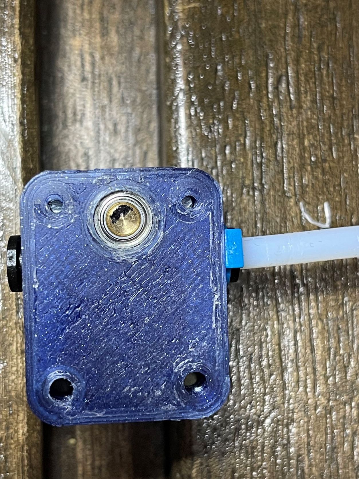
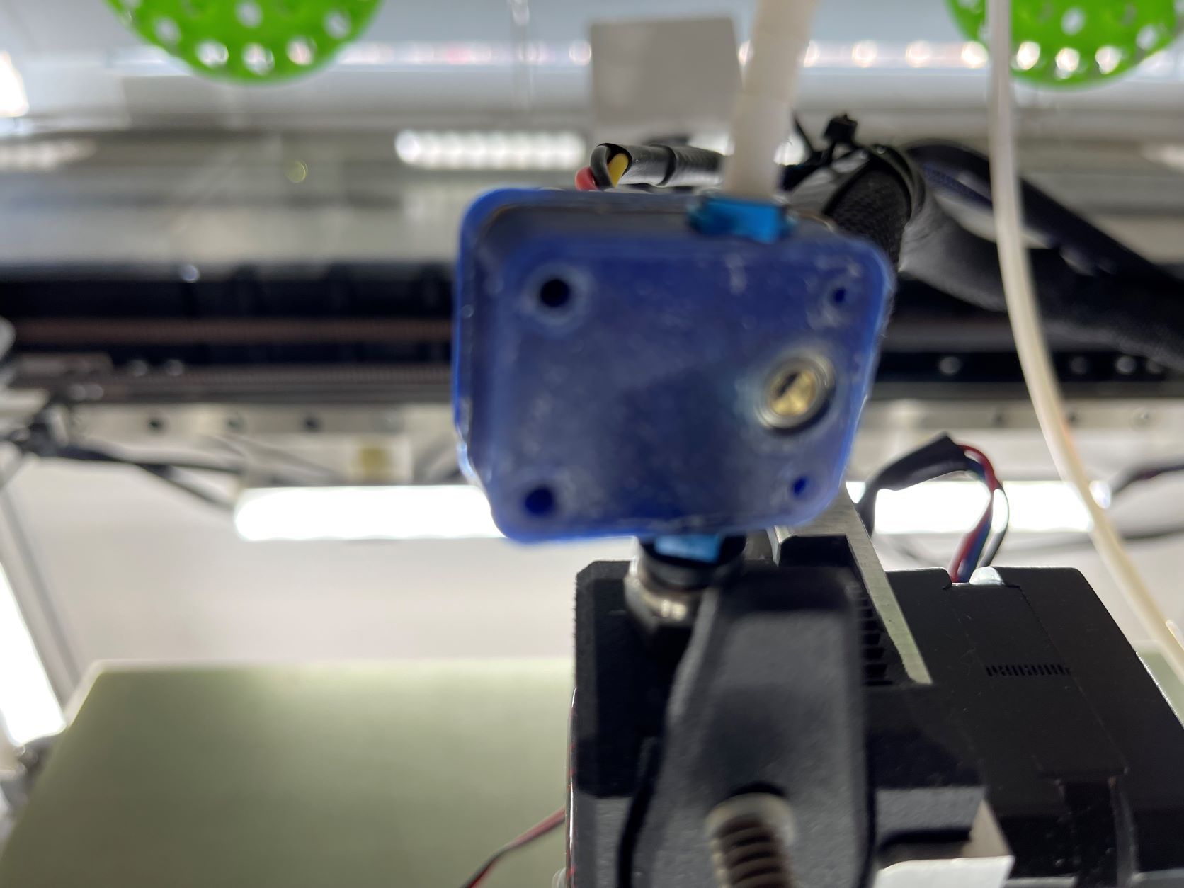
                            Photos of your sensor setup and printer? Maybe we can spot something.

                            Z-Bot CoreXY Build | Thingiverse Profile

                            wouldstainundefined 2 Replies Last reply Reply Quote 0
                            • wouldstainundefined
                              wouldstain @alankilian
                              last edited by

                              @alankilian I can tell you for certain the extruder is not clogging.
                              I've actually set up a macro to disable the MFM when printing PLA:

                                 M591 d0 s0
                              

                              This allows me to run entire PLA jobs without interruption but also without the protection of run-out detection. I was able to finish off the tail ends of two spools yesterday thanks to having the MFM enabled but there were several false-stops during the process.

                              1 Reply Last reply Reply Quote 0
                              • wouldstainundefined
                                wouldstain @Phaedrux
                                last edited by

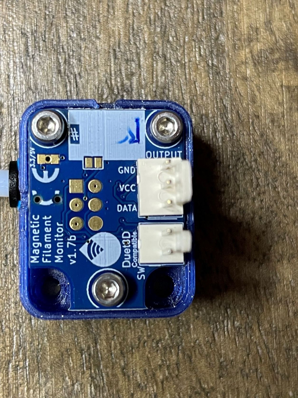
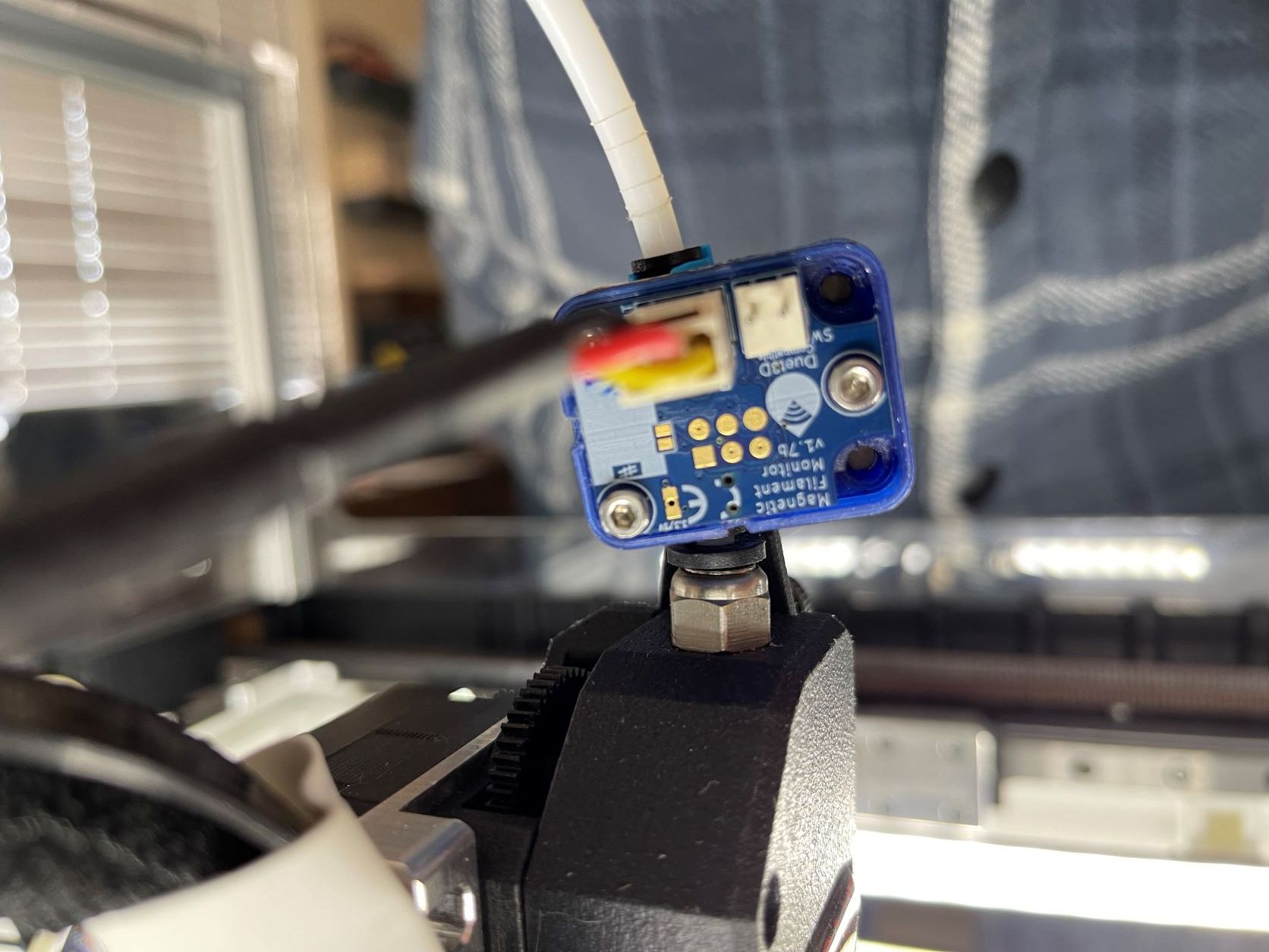
                                @phaedrux As soon as the current job is complete I'll get some photos.
                                Assuming you want to see it mounted as well as on the bench and disassembled.

                                1 Reply Last reply Reply Quote 0
                                • wouldstainundefined
                                  wouldstain @Phaedrux
                                  last edited by

                                  @phaedrux

                                  Photos as requested.
                                  Please let me know if there's something else you'd like a pic of.

                                  IMG-4154.jpg IMG-4153.jpg IMG-4152.jpg IMG-4151.jpg IMG-4150.jpg IMG-4149.jpg IMG-4148.jpg

                                  1 Reply Last reply Reply Quote 0
                                  • Phaedruxundefined
                                    Phaedrux Moderator
                                    last edited by

                                    Have you tried re-printing the casing in higher quality?

                                    Z-Bot CoreXY Build | Thingiverse Profile

                                    wouldstainundefined 2 Replies Last reply Reply Quote 0
                                    • wouldstainundefined
                                      wouldstain @Phaedrux
                                      last edited by

                                      @phaedrux I havent but I can although the casing is clean on the inside. I had some first layer issues IIRC and it still has some dry bedweld on it (got distracted and forgot to rinse).

                                      1 Reply Last reply Reply Quote 0
                                      • wouldstainundefined
                                        wouldstain @infiniteloop
                                        last edited by

                                        @infiniteloop I have the MFM sitting directly atop the extruder and the PTFE tube comes in close to vertical so I'm not concerned about the angle of the filament path.

                                        I am considering picking up a piece of copper tube from McMaster and replacing the bit of PTFE tubing connecting the MFM to the extruder but I really dont think that's where the problem is.

                                        I'm inclined to print a new casing and giving that a try as I noticed that the ring on the MFM sensor from the magnet rubbing was a partial circle which would indicate to me that there's a slight tilt to the magnet.

                                        I think an injection molded case would remove any uncertainty around it but I'm not certain that would resolve this issue.

                                        infiniteloopundefined 1 Reply Last reply Reply Quote 0
                                        • infiniteloopundefined
                                          infiniteloop @wouldstain
                                          last edited by

                                          @wouldstain said in MFM recurring error:

                                          I think an injection molded case would remove any uncertainty around it but I'm not certain that would resolve this issue.

                                          My MFM works reliably, the electronics are pretty well engineered. The - self-printed - case needed heavy postprocessing, I had to file, drill, cut and sand a lot. Especially the filament path and the idler are problematic, the often mentioned distance between magnet and sensor is no theme anymore since introduction of the 2 mm magnet in v2. So yes, an injection molded case would be helpful.

                                          Given the high precision of detected filament movement, a direct coupling with the extruder - or better, an integrated design - is still on my wish list …

                                          But, again: if the magnet rotates as intended, PCB and I2C transmission work flawlessly. @dc42 has made a remarkable job to ensure reliability of the data, so, as long as we get our cables right, we won't run into problems on this side. Simply put: it's the mechanics we have to take care of.

                                          wouldstainundefined 1 Reply Last reply Reply Quote 0
                                          • wouldstainundefined
                                            wouldstain @infiniteloop
                                            last edited by

                                            @infiniteloop No doubt! I'm still pretty new at this and I generally assume it's something I'm doing. Given what you're saying about post processing and my questionable print quality, I would not be surprised if there are tolerance issues with my casing.

                                            1 Reply Last reply Reply Quote 0
                                            • First post
                                              Last post
                                            Unless otherwise noted, all forum content is licensed under CC-BY-SA