Correction of heightmap is not really working
-
@sculpt-fabricator said in Correction of heightmap is not really working:
@fcwilt This has been great, I am having the exact same problems as @ICY_SNAKE with the same machine. V3.3, I have followed and made all the same changes.
But I am having a Errror: in file macro line 6 column 43: G31 : unknown
variable 'g_probe_z_trigger"I don't understand what that is ?
Did you create the variable in your config.g file as I specified in my example?
Frederick
Printers: a small Utilmaker style, a small CoreXY and a E3D MS/TC setup. Various hotends. Using Duet 3 hardware running 3.4.6
-
@fcwilt
Here is my Config.g; General preferences_________________________________________________________ G21 ; dimentions in mm G90 ; for X,Y,Z use absolute coordinate values M83 ; for E0,E1,etc use relative coordinate values M111 S0 ; Debug off M555 P2 ; Set output to look like Marlin M575 P0 B57600 S2 ; communication parameters for USB serial M575 P1 B57600 S1 ; Set auxiliary serial port baud rate and require checksum (for PanelDue) ; Network_____________________________________________________________________ M550 P"Big 60" ; set printer name M552 S1 ; enable (S1) networking (WiFi) M586 S1 P1 ;T0 ; enable (S1) FTP (P1) Disable TLS (T0) M586 S1 P2 ;T0 ; enable (S1) Telnet (P2) Disable TLS (T0) ;;M586 P0 S1 ; enable HTTP ;;M586 P1 S0 ; disable FTP ;;M586 P2 S0 ; disable Telnet ; mode control variables _____________________________________________________ global g_z_home = 5 ; can be used to always move Z to known height global g_z_datum_set = false ; can be used to prevent unneeded setting of Z=0 datum global g_map_mode = "300 point" ; determines which kind of height map is created/loaded global g_probe_mode = "two consecutive" ; determines if z proving used consecutive or averaging global g_level_mode = "4 point" ; determines if 3 or 4 points are used for leveling global g_print_beg_prime = 10 ; default - set desired in filament config.g global g_print_beg_retract = 0 ; default - set desired in filament config.g global g_print_end_retract = 0 ; default - set desired in filament config.g global g_print_end_mode = "heat off" ; determines if heaters are turned off when print is done ; Drives_________________________________________________________________________ ;Main board______________________________________________________________________ M569 P0 S0 ; Physical drive 0 . X1 M569 P1 S1 ; Physical drive 1 . X2 M569 P3 S1 ; Physical drive 3 . Main Extruder M569 P4 S0 ; Physical drive 4 . Secondary Extruder ;Duex5 board_____________________________________________________________________ M569 P5 S0 ; Physical drive 5 . Y M569 P6 S0 ; Physical drive 6 . Z1 (0,0) M569 P7 S0 ; Physical drive 7 . Z2 (600,0) M569 P8 S0 ; Physical drive 8 . Z3 (600,600) M569 P9 S0 ; Physical drive 9 . Z4 (0,600) ;Settings_________________________________________________________ M584 X0:1 Y5 Z6:7:8:9 E3:4 P3 ; Driver mapping U1 M671 X-189:-189:645:645 Y645:-64:-64:645 S10 ; Anticlockwise ;;M671 X-190:-190:641:641 Y-63:643:643:-63 S10 ; Anticlockwise ;___________________________________________________________________ M350 X16 Y16 I1 ; Configure microstepping with interpolation U16 M350 Z16 E16:16 I0 ; Configure microstepping without interpolation M92 X100.00 Y100.00 Z2000.00 E686:700 ; Set steps per mm U100.00 M566 X300 Y500 Z100.00 E120.00:120.00 P1 ; Set maximum instantaneous speed changes (mm/min) U240 M203 X18000.00 Y18000.00 Z300.00 E1200.00:1200.00 ; Set maximum speeds (mm/min) U9000.00 M201 X1000 Y1000 Z120.00 E250.00:250.00 ; Set accelerations (mm/s^2) U1000 ;M566 X240 Y360 Z30.00 E120.00:120.00 U240 P1 ; Set maximum instantaneous speed changes (mm/min) ;M203 X9000.00 Y9000.00 Z200.00 E1200.00:1200.00 U9000.00 ; Set maximum speeds (mm/min) ;M201 X1000 Y1000 Z120.00 E250.00:250.00 U1000 ; Set accelerations (mm/s^2) M204 P500 ; Set print and travel accelerations (mm/s^2) M906 X1800 Y1800.00 E1270:1270 I40 ; Set motor currents (mA) and motor idle factor in per cent (E1270 per dyze) U1800 M906 Z1800.00 I50 ; Set motor currents (mA) and motor idle factor in per cent M84 S100 ; Set idle timeout - 100 seconds ; Axis Limits M208 X0 Y0 Z-1 S1 ; set axis minima M208 X590 Y580 Z630 S0 ; set axis maxima ; Endstops ;;M574 X1 S1 P"xstop" ; configure switch-type (e.g. microswitch) endstop for low end on X via pin xstop ;;M574 U1 S1 P"e0stop" ; configure switch-type (e.g. microswitch) endstop for low end on X via pin xstop M574 X1 S1 P"xstop + e0stop" ; configure switch-type (e.g. microswitch) endstop for low end on X via pin xstop M574 Y2 S1 P"ystop" ; configure switch-type (e.g. microswitch) endstop for low end on Y via pin ystop ; add probe file ; global.g_probe_z_trigger ; global.g_probe_z_trigger = 1.9 ; default - set as appropriate for the Z probe M558 P9 C"^zprobe.in" H5 F120 T6000 A1 R1 ; set Z probe type to bltouch and the dive height + speeds M950 S0 C"duex.pwm5" ; set probe pin M98 P"config_probe.g" M556 S50 X0 Y0 Z0 ; set orthogonal axis compensation parameters woher kommt der test wie wurde der Winkel bestimmt Unklar! M376 H10 ; stop z-leveling after 10 layers ; Z-Probe ;M558 P9 C"^zprobe.in" H5 F120 T6000 A1 R1 ; set Z probe type to bltouch and the dive height + speeds ;M950 S0 C"duex.pwm5" ; set probe pin ;M98 P"config_probe.g" ; configure probe after a reboot or reset ;global g_probe_z_trigger = 1.8 ; default - set as appropriate for the Z probe ;;G31 P500 X-30 Y0 Z2.64 ; set Z probe trigger value, offset and trigger height **** Z height change + 0.29 **** ;;M556 S50 X0 Y0 Z0 ; set orthogonal axis compensation parameters ;;M557 X0:560 Y0:580 S90:108.75 ; define mesh grid and probe points, fine S30:36.25 ;;M376 H10 ; Height (mm) over which to taper off the bed compensation ; Heaters___________________________________________________________ M140 H-1 ; disable heated bed (overrides default heater mapping) ;M308 S0 P"bedtemp" Y"thermistor" A"Bed Heat" T100000 B3950 ; define bed temperature sensor ;M950 H0 C"bedheat" T0 Q10 ;heater 0 uses the bed_heat pin, sensor 0, PWM 10hz ;E0_________________________________________________________________ M308 S0 P"spi.cs1" Y"rtd-max31865" A"Main Extruder" ; create sensor number 1 as a PT100 sensor in first position daughterboard M950 H0 C"e0heat" T0 ; create nozzle heater output on e0heat and map it to sensor 0 M307 H0 B0 R2.004 C403.6:385.3 D14.93 S1.00 V23.8 ; PID calibration M143 H0 S450 ; set temperature limit for heater 0 to 450C ;E1_________________________________________________________________ M308 S1 P"spi.cs2" Y"rtd-max31865" A"Support Extruder" ; create sensor number 2 as a PT100 sensor in sec position daughterboard ;M950 H1 C"e1heat" T1 ; create nozzle heater output on e1heat and map it to sensor 1 TEMP OFF ;M307 H1 B0 S1.00 ; PID calibration TEMP OFF ;M143 H1 S450 ; set temperature limit for heater 1 to 450C TEMP OFF ;E4_________________________________________________________________ M308 S1 P"duex.e4temp" Y"thermistor" T100000 B4267 ; configure sensor 1 as thermistor on pin e1temp M950 H5 C"duex.e4heat" T1 ; create nozzle heater output on e4heat and map it to sensor 4 ;M307 H5 B0 S1.00 ; PID calibration M143 H5 S120 ; set temperature limit for heater 1 to 120C ; Fans & LED___________________________________________________________ M950 F0 C"fan0" Q500 ; create fan 0 on pin fan0 and set its frequency M106 P0 S0 H-1 ; set fan 0 value. Thermostatic control is turned on M950 F1 C"fan1" Q500 ; create fan 1 on pin fan1 and set its frequency M106 P1 S0 H-1 ; set fan 1 value. Thermostatic control is turned on M950 F2 C"fan2" Q500 ; create air filter fan on fan 2 on pin fan2 and set its frequency M106 P2 S0 H-1 ; set fan 2 value. Thermostatic control is turned on M950 F7 C"!duex.fan7" Q500 ; create LED on pin fan7 and set its frequency M106 P7 S0 H-1 ; Disable fan channel for LED M106 P7 S255 ; remove ";" to set the LED to full brightness by default M950 F3 C"duex.fan3" Q500 ; create fan 3 on pin fan3 and set its frequency M106 P3 S1 H-1 ; set fan 3 value. Thermostatic control is turned on Bed relay to on ; Tools______________________________________________________________ ;T0_________________________________________________________________ M563 P0 S"E0 Main" D0 H0 F0 ; define tool 0 G10 P0 X0 Y0 Z0 ; set tool 0 axis offsets G10 P0 R0 S265 ; set initial tool 0 active and standby temperatures to 0C ;T1_________________________________________________________________ M563 P1 S"E1 Support" D1 H1 F1 ; define tool 1 G10 P1 X0 Y65 Z0 ; set tool 1 axis offsets Y-2 moves filament 2mm to back of machine X-1 moves filament 1mm to the right G10 P1 R0 S265 ; set initial tool 1 active and standby temperatures to 0C ;T2____________________________________________________________________ ;M563 P2 S"BED TEMP" H-1 ;Temp off ;G10 P2 ;Temp off ;T3___________________________________________________________________ M563 P3 S"CHAMBER TEMP" H5 G10 P3 R0 S40 ; Custom settings__________________________________________________ M591 D0 P1 C"duex.e2stop" S1 ; Regular filament sensor for E0 M591 D1 P1 C"duex.e3stop" S1 ; Regular filament sensor for E1 ;M950 P2 C"fan2" Q500 M42 P2 S255 ; Start up air filter ; Automatic power saving____________________________________________ M911 S22.5 R29.0 P"M913 X0 Y0 G91 M83 G1 Z3 E-5 F1000" ; Set voltage thresholds and actions to run on power loss. Power Failure Pause -
@fcwilt
I am just not picking up this coding. I have spent 5 days straight on this.Question - So when a Error pops up it is there to tell you there is a problem and to point you in the direction of the problem to fix the issue, I assume ?
So, when I get a -
Error: in file macro line 44 column 10: meta command: 'break' was not inside a loopHow do I know what macro, and column is the spot on line 10?
-
Amazing.
What are the odds you would have global variables with the exact same names as mine.
")
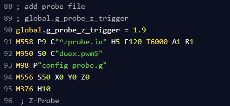
In any case the variable mentioned in the error appears more than once in your config.g file but they are all commented out.
Enable the second one (the one with 1.9) by removing the comment character.
Also I see these two commands:
M558 P9 C"^zprobe.in" H5 F120 T6000 A1 R1
M950 S0 C"duex.pwm5"
They should be moved to your config_probe.g file. If they are already in that file simply remove them from your config.g file.
Frederick
-
@sculpt-fabricator said in Correction of heightmap is not really working:
@fcwilt
I am just not picking up this coding. I have spent 5 days straight on this.Question - So when a Error pops up it is there to tell you there is a problem and to point you in the direction of the problem to fix the issue, I assume ?
So, when I get a -
Error: in file macro line 44 column 10: meta command: 'break' was not inside a loopHow do I know what macro, and column is the spot on line 10?
Well I test each macro as I code it so I know which macro is creating the error. Then since the error messages tells me what line and column I can focus in on the error.
I don't move on to some other coding until the macro is error free.
Do you have a bed.g file?
If so post it here, please.
Frederick
-
Ok so me making 100 changes at once is not good ! LOL
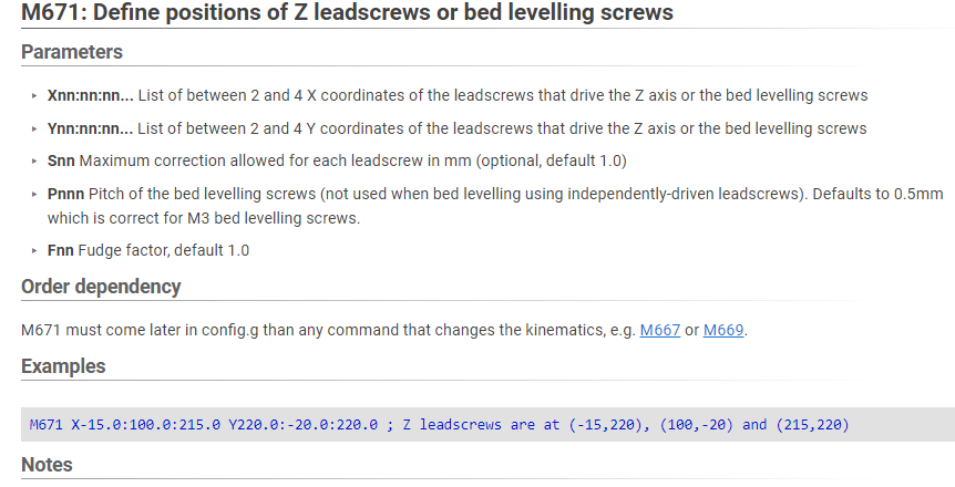
;M98 P"config_probe.g"        ; insure probe is using most recent configuration values

G29 S2                       ; cancel mesh bed compensation
M290 R0 S0                   ; cancel baby stepping

G90                          ; absolute moves
G1 Z5 F99999                 ; insure Z starting position is high enough to avoid probing errors

; M671: Define positions pf manual bed levelling screws or Z leadscrews

; Xnn:nn:nn... list of between 2 and 4 X coordinates of the leadscrews that drive the Z axis or the bed levelling screws
; Ynn:nn:nn... list of between 2 and 4 Y coordinates of the leadscrews that drive the Z axis or the bed levelling screws
; Snn          maximum correction allowed for each leadscrew in mm (optional, default 1.0)
; Pnnn         pitch of the bed levelling screws (not used when bed levelling using independently-driven leadscrews). Defaults to 0.5mm which is correct for M3 bed levelling screws
; Fnn          fudge factor, default 1.0

M671 X-189:-189:645:645 Y645:-64:-64:645 S10 ; Anticlockwise

; --- level bed ---

 while true

; run leveling pass

G30 P0 X10 Y10 Z-99999      ; probe near a leadscrew
G30 P1 X570 Y10 Z-99999     ; probe near a leadscrew
G30 P2 X570   Y570   Z-99999     ; probe near a leadscrew
G30 P3 X10   Y570   Z-99999 S4  ; probe near a leadscrew and calibrate 4 motors

   if move.calibration.initial.deviation < 0.02

    break

   ; check pass limit - abort if pass limit reached

   if iterations = 5

     M291 P"Bed Leveling Aborted" R"Pass Limit Reached"
     abort "Bed Leveling Aborted - Pass Limit Reached"

 ; --- finish up ---

 ; --- set Z=0 datum which can be affected by leveling ---

 G1 X270 Y270 ; move probe to center of bed - set values aaa and bbb as appropriate
 G30          ; do single probe which sets Z to trigger height of Z probe
; config_probe.g ; config the probe and call the other files.g M558 P9 C"^zprobe.in" H5 F120 T6000 A1 R1 M950 S0 C"duex.pwm5" G31 P25 X-30 Y0 Z1.688 ; set Z probe trigger value, offset and trigger height (larger value is closer)G31 P500 X-18 Y24 Z2.917 -
that is my bed.g
and config_probe.g -
@sculpt-fabricator said in Correction of heightmap is not really working:
that is my bed.g
and config_probe.gOK your config_probe.g file looks good. So remove the commands I mentioned from config.g
Please upload your bed.g file using the "upload file" tag. I will edit it to correct the errors.
You simply have not used the required indentation.
Frederick
Printers: a small Utilmaker style, a small CoreXY and a E3D MS/TC setup. Various hotends. Using Duet 3 hardware running 3.4.6
-
Got the lines changed in the config.g
Here is the bed.g
bed.g -
Here is homeall.g
; homeall.g
; called to home all axes

G91                    					; relative positioning

G1 H2 Z5 F200          		            ; lift Z relative to current position
G1 H1 X-605 Y605 F3000 		            ; move quickly to X and Y axis endstops and stop there (first pass)
G1 H2 X5 Y-5 F600      		            ; go back a few mm
G1 H1 X-605 Y605 F600  		            ; move slowly to X and Y axis endstops once more (second pass)

G90                    		            ; absolute positioning
M98 P"config_probe.g"
G30                    		            ; home Z by probing the bed
G1
mesh.g
M98 P"config_probe.g" ; insure probe is using most recent configuration values G29 S2 ; cancel mesh bed compensation M290 R0 S0 ; cancel baby stepping G90 ; absolute moves ; --- set Z=0 datum which is needed for creating a heightmap G1 Z5 F99999 ; insure Z starting position is high enough to avoid probing errors G1 X270 Y270 ; move probe to center of bed - set values aaa and bbb as appropriate G30 ; do single probe which sets Z to trigger height of Z probe M557 X0:560 Y0:580 S58 ; define mesh grid 420 points S58 G28 G29 S0 ; probe bed and create height map -
So another question. Modix had a Macro -
Automatic tilt calibration + Bed Compensation - 101 pointsThat Macro has all changed now with your code correct ?
So how do I run the bed tilt calibration
and the bed probe calibration ?I am confused on it I wipe those clean and add a M98 P"bed.g"
and run it trough the macro
or just type that into the console comand ? -
The current approach that the DWC expects is this:
- the file mesh.g is used to create the height map needed for Mesh Bed Compensation.
- the file bed.g is used for Manual or Automatic Bed Leveling.
A G29 command executes mesh.g and creates the height map.
To use the height map you would have a G29 S1 command somewhere in your print start code.
A G32 command executes bed.g.
I use G32 as part of my home all code.
So it looks like you are already using the correct approach.
Frederick
-
Printers: a small Utilmaker style, a small CoreXY and a E3D MS/TC setup. Various hotends. Using Duet 3 hardware running 3.4.6
-
@fcwilt
Thank you very very much, I will give it a try -
@fcwilt
I got this -

Does that command need a ; in front of it ?
-
Sorry there is a missing comment in front of that line.
It should be this:
; --- set Z=0 datum which can be affected by leveling ---

G1 X270 Y270 ; move probe to center of bed - set values aaa and bbb as appropriate
G30          ; do single probe which sets Z to trigger height of Z probe
Printers: a small Utilmaker style, a small CoreXY and a E3D MS/TC setup. Various hotends. Using Duet 3 hardware running 3.4.6
-
@fcwilt
Ok now I cant get the bed tilt leveling right.
I am not understanding the placement of z screwsbed.g M671 , needs to match the config.g M671 correct ??
M671 X-189:640:640:-189 Y643:643:-64:-64 S10 Anticlockwise- why does it say anticlockwise
- In my bed.g it says to run the probe pattern -
 ; run leveling pass

  G30 P0 X5 Y5 Z-99999      ; probe near a leadscrew
  G30 P1 X570 Y5 Z-99999     ; probe near a leadscrew
  G30 P2 X570   Y580   Z-99999     ; probe near a leadscrew
  G30 P3 X5   Y580   Z-99999 S4  ; probe near a leadscrew and calibrate 4 motors
But that is running from the left rear , clockwise
But when it runs the Tilt calibration, it starts at the front left and go's to the front right, and so on, Anticlockwise.
In the Gcode Directory it examples M671 going clockwise
I am stumped !!
-
@fcwilt
also If I skip the tilt calibration and go to Bed compensation,
I can strategically place a high spot under one of the probe points.
and it shows me that the map is 90 deg out.
to correct it, it would have to turn 90 deg Anticlockwise.if that helps
-
Since we are putting everything related to bed leveling in bed.g there should not be a M671 command in config.g.
I don't know why it says "anticlockwise" - I did not put that there.
As I recall what does need to match up is the order of the Z steppers in the M584 command and the order of the positions specified in the M671 command.
I also have the G30 commands probe the bed in the order specified in the M671 command though I don't know if that is a requirement.
But my bed leveling works so it doesn't hurt to keep everything in the same order, even if it is not required.
The height map is not related to anything being done in bed leveling.
Frederick
-
Ok so still having some problems
We are following these instructions for setting the Z=0 datumWe run the Z offset macro that you made to move to the center of the bed
and probe to set the config_probe.g G31 ZWe got a reading of 1.752
So we changed that in the Config.probe.g
(do we need to change it anywhere else ? for example mesh.g
? global_mesh_g in config.g file ? )Then we run your probe in center of be code - With a added Z0
G1 X{((move.axes[0].max + move.axes[0].min) / 2) - sensors.probes[0].offsets[0]}, Y{((move.axes[1].max + move.axes[1].min) / 2) - sensors.probes[0].offsets[1]}, F1800 Z0It should be at the same 1.752 but it is not. Its further away from the
bed than that by .40so we go back and add that .40 to the 1.752 = 2.152 in the config.probe.g
it didn't work. we are still further away.
its not saving it for some reason.