Z-drives not moving, new Duet3
-
@heide said in Z-drives not moving, new Duet3:
Error: Bad command: Put G/M Codes in here to run when Tool 0 is about to be activated
Just to explain this error; you have
T0in your config.g, so the tool change macros get run. As no tool is selected, only tpre.g and tpost.g are being run. It looks like the text at the beginning of one of these files is not commented out correctly, with a semicolon;as the first character.I've had a good look at your files, but I can't see what's stopping the homing working. I think try @JoergS5 suggestion of stepping through the GCode of homeall.g and homez.g, and see what works correctly and what doesn't.
Ian
Bed-slinger - Mini5+ WiFi/1LC | RRP Fisher v1 - D2 WiFi | Polargraph - D2 WiFi | TronXY X5S - 6HC/Roto | CNC router - 6HC | Tractus3D T1250 - D2 Eth
-
@droftarts thanks for the time you have used. And I am really sad that there are no errors, because I then maybe have a problem. I just can get it. It can run with no errors, with the code I postes earlyer today, when I tested. I will do as @JoergS5 proposed.
Voron CoreXY with Duet 3 + expansion + PanelDue 7i - 300 * 300 * 300 and Hemera Revo
-
@heide said in Z-drives not moving, new Duet3:
G1 H1 X-240 Y-240 F3000
I have two additional ideas for your tests. The -240 will probably not be sufficient, because your M208 says the axes are 300 long, so I would take higher values. The goal of this line is that one of the endstops is triggered.
The second idea is, when I run G1 commands in the DWC command line, I prefix G90 or G91, so I am sure the command runs in the correct mode. E.g.:
G91 G1 X100
This is important in the homeall, because there are several changes of G90 G91 inside. (NB: I don't mean that homeall is wrong: the G91 G90 sets mode for the following lines. I mean, to be sure you're in the right mode when executing it line by line) -
Okey, what I know for now, is that it seems that the endstops X and Y prohibit the gantry to move after they are activated, it is like they hold on to it (locks it). I tried to force (not my intension, but needed to see if I could move the gantry when I did) the gantry away form the endstops (X and Y), and then I can move it. I will need to test some more, but that must be later. (Need to be somewhere else) But I will be back
") I'm so happy for this community, and your help, I hope I can contribute some day
I'm so happy for this community, and your help, I hope I can contribute some day Voron CoreXY with Duet 3 + expansion + PanelDue 7i - 300 * 300 * 300 and Hemera Revo
-
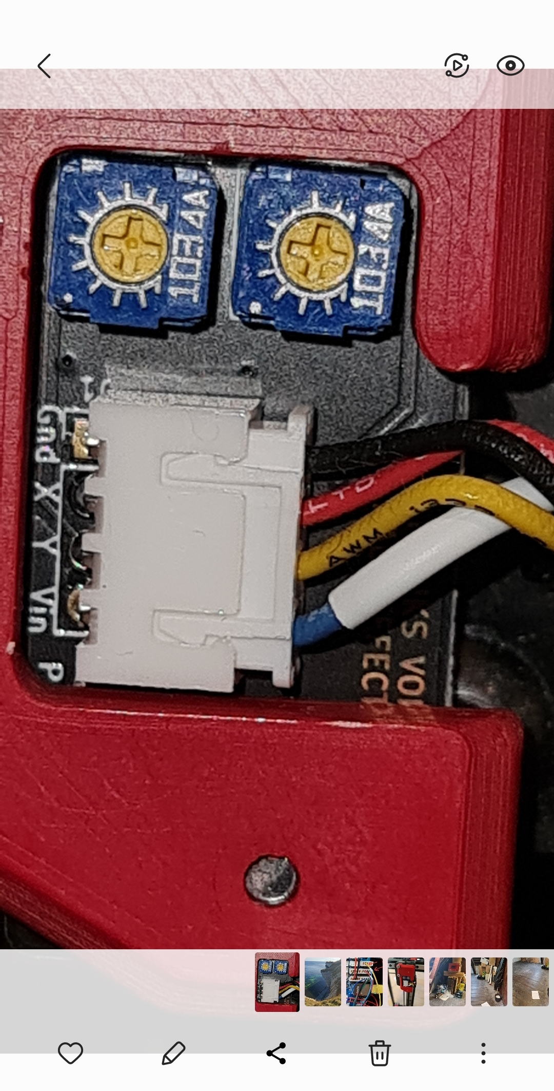
Another Thing I forgot to mension. The endstop is a Hall Effect type
-
@heide if you post a picture of the endstops, someone may tell you from experience what can be the reason for the locking.
I am pleased to hear that you are approaching a solution. -
@heide said in Z-drives not moving, new Duet3:
@droftarts And I am really sad that there are no errors, because I then maybe have a problem.
Don’t be sad! There is probably an error, just I didn’t see it. Use this as a learning experience!
Ian
-
-
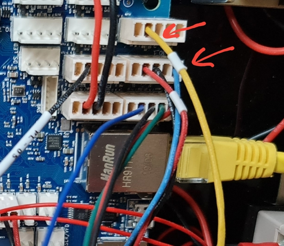
@heide the only information I found is in https://docs.duet3d.com/en/User_manual/Connecting_hardware/Sensors_endstops that the 5V wire should be connected to 5V of the IO connector, but you've probably done that already.
-
@joergs5 happy to have pictures on my Phone when I'm not at home. This is the connection for the Hall sensor. And I think it is corrct connected
Voron CoreXY with Duet 3 + expansion + PanelDue 7i - 300 * 300 * 300 and Hemera Revo
-
The yello Wire has common GND from the other connnection
Voron CoreXY with Duet 3 + expansion + PanelDue 7i - 300 * 300 * 300 and Hemera Revo
-
@heide if the blue wire is 5V, than it's correct. (the colors differ from the Voron page, you should check it. Often, red is voltage, black is ground, other colors are signals. But if you DIY wiring, you can choose colors as you like. Your wires black-red-yellow-blue)
-
@heide Hi, if you're using the hall effect sensor in its default location, may I ask why you define your X and Y endstops to be low end?
Normally on a Voron, the X0 and Y0 is front left corner of the bed. And you home at max X and Y.
Here's my endstop configuration:
; Endstops
M574 X2 S1 P"121.io0.in"                       ; configure active-high endstop for high end on X via pin 121.io0.in
M574 Y2 S1 P"0.io1.in"                         ; configure active-high endstop for high end on Y via pin io1.in
However, I do not use the hall effect, but that's just an inverse away.
Also, a simple M119 will tell you all you need to know, one where they should be activated and one where they should not be.
-
@joergs5 yes that correct. I was confused about that. But the wires was made when I recieved the Kit. But I did have to change the plugs, to work with the board. As you can see the red wire has a label with an X or a Y. Can't remember
@gixxerfast on my Voron the endstop i placed under the gantry on the right bottom side. X i homed in that right position offcause, but Y is homed when the Gantry moves to the bottom, on a fixed magnet that is placed on the Z3 liner.
-
The Hall effect sensor is wired correctly.
-
@Gixxerfast I was on a small road trip when I read you text, and have misread it. I have now read it again, and can see that I also have the high end in the bottom of the right side. I will now reconfigure the Config and home files to this. Let see if this helps
-
I have now tested all possible variations, high and low end with and with out ^!. It stops working after homing X and Y.
Now I'm thinking it could be the endstop of Z that is blocking, not the X or Y. It would make sence, since it stops there. If it sees the endstop on, then it won't go. Or maybe the signal should be inverted. I will try this tomorrow.
Voron CoreXY with Duet 3 + expansion + PanelDue 7i - 300 * 300 * 300 and Hemera Revo
-
@heide I'm sure your config.g has changed since you did this, but this is your config.g from earlier:
M574 X1 S1 P"!io1.in"                                      ; configure switch-type (e.g. microswitch) endstop for low end on X via pin !io0.in
M574 Y1 S1 P"!io2.in"                                      ; configure switch-type (e.g. microswitch) endstop Y1 = low-end on Y via pin !io1.in
M574 Z1 S1 P"io3.in"                                       ; configure switch-type (e.g. microswitch) endstop U1 = low-end, S1 = active-high (NC) on Z via pin io3.in
If all endstops are these hall effect sensors, then they should all be the same. And they will either have active high or active low outputs (not to be confused with 'high' and 'low' end of the axis, though). So they will need to either all have
!before the pin name (as X and Y do) or none of them will. From https://docs.duet3d.com/User_manual/Connecting_hardware/Sensors_endstops#h-33v-compatible-hall-sensorSimple Hall sensors normally have active low outputs, so put ! at the start of the pin name if using RRF 3.x
...
If your Hall sensor is a circuit board with a sensitivity adjustment potentiometer on it, then it may provide an active high output instead of active low.Realistically, use M119 with the axes away from the endstops to check the endstop status. They should all report "[axis letter]: not stopped". With each axis at the endstop, they should report "[axis letter]: at [min or max] stop". If an axis is reporting the wrong way around, add or remove the
!in front of the pin name for that axis.Don't use pull up resistor
^with Duet 3. The Duet 3 already has a pull up resistor built-in.Ian
-
@heide to add to what @droftarts said, if you use a second hall sensor for Z and it is connected like on the image above at IO_3, then the 5V of this sensor needs to be connected to 5V also. Otherwise the signal has no reference and the sensor has no power.
edit: if Z is microswitch, see next comment.IO_4 Z probe is also strange, it has only one wire connected.
-
@heide I realise that there are only two wires going to IO_3 (on GND and IO3.in), so likely it's a microswitch endstop on Z, and hall sensors on X and Y. The Voron guide is here: https://docs.vorondesign.com/build/electrical/#endstop-wiring and it is recommended to use NC connections with Duet, too. This should means you don't need the
!before the pin name for the Z endstop.However, a broken wire on an NC configured endstop will always register as triggered, ie at min/max stop. So test the endstop with M119, and check it changes state.
Ian
Bed-slinger - Mini5+ WiFi/1LC | RRP Fisher v1 - D2 WiFi | Polargraph - D2 WiFi | TronXY X5S - 6HC/Roto | CNC router - 6HC | Tractus3D T1250 - D2 Eth