New heated enclosure printer
-
OK, I was able to get it all connected to the PC, uploaded RRF3.4 and was able to set the network parameters and get to the Duet Web Control page on a browser.
I did have some issues with the paneldue7i, so any advise you can offer is appreciated, @dc42 .
The paneldue 7i was connected and seemed to respond very slowly to any touch commands. I had the 4 wire and the modified 10 pin ribbon connector attached. I went to upgrade the paneldue 7i firmware according to https://docs.duet3d.com/User_manual/RepRapFirmware/Updating_PanelDue. It seemed to complete successfully, there were no errors in the console and the last message was:
Progress: 100%
Writing PanelDue flash options
Restarting PanelDueAfter the update the paneldue was completely a white screen. I tried pressing reset with no change. I powered it all down then back up and was able to reconnect to the Duet web page, but still nothing from the paneldue 7i but a white screen. Can you brick a paneldue?
Before trying the PC/usb approach I wanted to see if there was something I was doing wrong with the Duet approach.
-
@coseng said in New heated enclosure printer:
Before trying the PC/usb approach I wanted to see if there was something I was doing wrong with the Duet approach.
Use the PC/USB approach. Chances are you had an older version of PanelDue firmware on there that wasn't ready for updating via duet.
-
@phaedrux Thanks, that worked!
Now a couple of more questions. Below is my first config.g file. I have not run it yet as I have to run a new AC power socket to plug into, so all of my playing around so far has been only with the USB and network cable attached.
First question from the RRF config tool on i/o mapping tab: PWM Control Channel (BLTouch only) should be set to what value? The BL Touch channels selected on the prvious page are not selectable on this drop down. I left it not assigned, but on the next page the BLTouch entry was greyed out. the BLTouch is on a 1LC toolboard. and all 5 wires are connected as shown in the wiki, so am not sure what this is referring to or how it would be wired.
I have a Z limit switch at about z=0 (or can be positioned wherever is convienent) and a BL Touch. What is the preferred way to home Z? Is the limit switch even needed?
I am running the 5V line that supplies the BoB with power to generate proper level clearpath signals from IO_3_out. What would be the command to turn this output on to power the steppers?
Also, not sure if it should work with no 24V supplied, but the Paneldue 7i upgraded fine and displayed a proper screen when plugged into a USB cable, but when plugged into the 6HC (powered by usb) with a 4 wire connector and 10/7 pin ribbon cable (both are correct) it only gives me a white screen and does not respond to touches. Also, a reset does not seem to do anything.
; Configuration file for Duet 3 (firmware version 3.3)
; executed by the firmware on start-up
;
; generated by RepRapFirmware Configuration Tool v3.3.10 on Wed Apr 13 2022 22:08:04 GMT-0400 (Eastern Daylight Time); General preferences
M575 P1 S1 B57600 ; enable support for PanelDue
G90 ; send absolute coordinates...
M83 ; ...but relative extruder moves
M550 P"hyperprinter" ; set printer name
M669 K1 ; select CoreXY mode; Wait a moment for the CAN expansion boards to start
G4 S2; Network
M552 P192.168.2.1 S1 ; enable network and set IP address
M553 P255.255.255.0 ; set netmask
M554 P192.168.2.20 ; set gateway
M586 P0 S1 ; enable HTTP
M586 P1 S0 ; disable FTP
M586 P2 S0 ; disable Telnet; Drives
M569 P0.1 S1 ; physical drive 0.1 goes forwards
M569 P0.2 S1 ; physical drive 0.2 goes forwards
M569 P0.0 S1 ; physical drive 0.0 goes forwards
M569 P121.0 S1 ; physical drive 121.0 goes forwards
M584 X0.1 Y0.2 Z0.0 E121.0 ; set drive mapping
M350 X32 Y32 Z8 E16 I1 ; configure microstepping with interpolation
M92 X56.14 Y56.14 Z320.00 E837.00 ; set steps per mm
M566 X900.00 Y900.00 Z60.00 E120.00 ; set maximum instantaneous speed changes (mm/min)
M203 X6000.00 Y6000.00 Z1800.00 E1200.00 ; set maximum speeds (mm/min)
M201 X500.00 Y500.00 Z20.00 E250.00 ; set accelerations (mm/s^2)
M906 X300 Y300 Z3900 E1600 I30 ; set motor currents (mA) and motor idle factor in per cent
M84 S30 ; Set idle timeout; Axis Limits
M208 X-320 Y-290 Z0 S1 ; set axis minima
M208 X320 Y290 Z950 S0 ; set axis maxima; Endstops
M574 X1 S1 P"121.io2.in" ; configure switch-type (e.g. microswitch) endstop for low end on X via pin 121.io2.in
M574 Y1 S1 P"io1.in" ; configure switch-type (e.g. microswitch) endstop for low end on Y via pin io1.in
M574 Z1 S2 ; configure Z-probe endstop for low end on Z; Z-Probe
M950 S0 C"io7.out" ; create servo pin 0 for BLTouch
M558 P9 C"121.io0.in+121.io0.out" H5 F120 T6000 ; set Z probe type to bltouch and the dive height + speeds
G31 P500 X0 Y0 Z2.5 ; set Z probe trigger value, offset and trigger height
M557 X-300:300 Y-250:250 S100 ; define mesh grid; Heaters
M308 S0 P"temp0" Y"pt1000" ; configure sensor 0 as PT1000 on pin temp0
M950 H0 C"out0" T0 ; create bed heater output on out0 and map it to sensor 0
M307 H0 B0 S1.00 ; disable bang-bang mode for the bed heater and set PWM limit
M140 H0 ; map heated bed to heater 0
M143 H0 S120 ; set temperature limit for heater 0 to 120C
M308 S1 P"temp1" Y"pt1000" ; configure sensor 1 as PT1000 on pin temp1
M950 H1 C"out1" T1 ; create chamber heater output on out1 and map it to sensor 1
M307 H1 B0 S1.00 ; disable bang-bang mode for the chamber heater and set PWM limit
M141 H1 ; map chamber to heater 1
M143 H1 S280 ; set temperature limit for heater 1 to 280C
M308 S2 P"121.temp0" Y"pt1000" ; configure sensor 2 as PT1000 on pin 121.temp0
M950 H2 C"121.out0" T2 ; create nozzle heater output on 121.out0 and map it to sensor 2
M307 H2 B0 S1.00 ; disable bang-bang mode for heater and set PWM limit
M143 H2 S320 ; set temperature limit for heater 2 to 320C; Fans
M950 F0 C"out4" Q500 ; create fan 0 on pin out4 and set its frequency
M106 P0 S1 H-1 ; set fan 0 value. Thermostatic control is turned off
M950 F1 C"out5" Q500 ; create fan 1 on pin out5 and set its frequency
M106 P1 S1 H-1 ; set fan 1 value. Thermostatic control is turned off
M950 F2 C"121.out2" Q500 ; create fan 2 on pin 121.out2 and set its frequency
M106 P2 S1 H-1 ; set fan 2 value. Thermostatic control is turned off; Tools
M563 P0 D0 H1:2 F2 ; define tool 0
G10 P0 X0 Y0 Z0 ; set tool 0 axis offsets
G10 P0 R0 S0 ; set initial tool 0 active and standby temperatures to 0C; Custom settings are not defined
Thanks again for all the help on this project!
Chris
Cosentino Engineering -
@Phaedrux One more question, I saw the paneldue initialization line at the top of config.g, but nothing metioning the SD card access through the temperature daughterboard connector: M950 D1 C"spi.cs0+spi.cs2" . Does this need to be added manually or does the M575 take are of it?
-
@coseng said in New heated enclosure printer:
M558 P9 C"121.io0.in+121.io0.out"
It's not showing the PWM control channel in the drop down because you somehow have both of them selected for the probe input.
You can manually edit the config.g to correct it like this.
; Z-Probe
M950 S0 C"121.io0.out" ; create servo pin 0 for BLTouch
M558 P9 C"121.io0.in" H5 F120 T6000
@coseng said in New heated enclosure printer:
Does this need to be added manually or does the M575 take are of it?
You'll have to manually add that
-
@phaedrux OK, got that taken care of. Was confused that the Modulation Pin needs to be not defined.
I installed AC power and powered it up. Nothing smoked, so that was a good step. I do of course have a couple of problems:
-1LC toolboard is not in CAN sync (fast blinking LED) tried reset to factory but no go. I'm pretty sure the wiring is correct. The extruder fan is on. Vin and 5V leds are lit. tried sending a query over the web interface with this response:
Error: M115: Response timeout: CAN addr 121, req type 6024, RID=14
-chamber temp sensor is reading at 2000C, but a multimeter reads 226kohm across the plug, which is two pt1000 sensors in series.
-when I go to home an axis I get a 'failed to enable endstops error'
Here's the config.g file:
; Configuration file for Duet 3 (firmware version 3.3)
; executed by the firmware on start-up
;
; generated by RepRapFirmware Configuration Tool v3.3.10 on Thu Apr 14 2022 23:52:03 GMT-0400 (Eastern Daylight Time); General preferences
M575 P1 S1 B57600 ; enable support for PanelDue
G90 ; send absolute coordinates...
M83 ; ...but relative extruder moves
M550 P"hyperprinter" ; set printer name
M669 K1 ; select CoreXY mode; Wait a moment for the CAN expansion boards to start
G4 S2; Network
M552 P192.168.2.1 S1 ; enable network and set IP address
M553 P255.255.255.0 ; set netmask
M554 P192.168.2.20 ; set gateway
M586 P0 S1 ; enable HTTP
M586 P1 S0 ; disable FTP
M586 P2 S0 ; disable Telnet; Drives
M569 P0.1 S1 ; physical drive 0.1 goes forwards
M569 P0.2 S1 ; physical drive 0.2 goes forwards
M569 P0.0 S1 ; physical drive 0.0 goes forwards
M569 P121.0 S1 ; physical drive 121.0 goes forwards
M584 X0.1 Y0.2 Z0.0 E121.0 ; set drive mapping
M350 X32 Y32 Z8 E16 I1 ; configure microstepping with interpolation
M92 X56.14 Y56.14 Z320.00 E837.00 ; set steps per mm
M566 X900.00 Y900.00 Z60.00 E120.00 ; set maximum instantaneous speed changes (mm/min)
M203 X18000.00 Y18000.00 Z3000.00 E1200.00 ; set maximum speeds (mm/min)
M201 X500.00 Y500.00 Z20.00 E250.00 ; set accelerations (mm/s^2)
M906 X300 Y300 Z3900 E1500 I30 ; set motor currents (mA) and motor idle factor in per cent
M84 S20 ; Set idle timeout; Axis Limits
M208 X-320 Y-290 Z0 S1 ; set axis minima
M208 X320 Y290 Z950 S0 ; set axis maxima; Endstops
M574 X1 S1 P"121.io2.in" ; configure switch-type (e.g. microswitch) endstop for low end on X via pin 121.io2.in
M574 Y1 S1 P"io1.in" ; configure switch-type (e.g. microswitch) endstop for low end on Y via pin io1.in
M574 Z1 S2 ; configure Z-probe endstop for low end on Z; Z-Probe
M950 S0 C"121.io0.out" ; create servo pin 0 for BLTouch
M558 P9 C"121.io0.in" H5 F120 T6000 ; set Z probe type to bltouch and the dive height + speeds
G31 P500 X0 Y0 Z2.5 ; set Z probe trigger value, offset and trigger height
M557 X-300:300 Y-250:250 S100 ; define mesh grid; Heaters
M308 S0 P"temp0" Y"pt1000" ; configure sensor 0 as PT1000 on pin temp0
M950 H0 C"out0" T0 ; create bed heater output on out0 and map it to sensor 0
M307 H0 B0 S1.00 ; disable bang-bang mode for the bed heater and set PWM limit
M140 H0 ; map heated bed to heater 0
M143 H0 S120 ; set temperature limit for heater 0 to 120C
M308 S1 P"temp2" Y"pt1000" ; configure sensor 1 as PT1000 on pin temp2
M950 H1 C"out1" T1 ; create chamber heater output on out1 and map it to sensor 1
M307 H1 B0 S1.00 ; disable bang-bang mode for the chamber heater and set PWM limit
M141 H1 ; map chamber to heater 1
M143 H1 S150 ; set temperature limit for heater 1 to 150C
M308 S2 P"121.temp0" Y"pt1000" ; configure sensor 2 as PT1000 on pin 121.temp0
M950 H2 C"121.out0" T2 ; create nozzle heater output on 121.out0 and map it to sensor 2
M307 H2 B0 S1.00 ; disable bang-bang mode for heater and set PWM limit
M143 H2 S320 ; set temperature limit for heater 2 to 320C; Fans
M950 F0 C"out4" Q500 ; create fan 0 on pin out4 and set its frequency
M106 P0 S1 H-1 ; set fan 0 value. Thermostatic control is turned off
M950 F1 C"out5" Q500 ; create fan 1 on pin out5 and set its frequency
M106 P1 S1 H-1 ; set fan 1 value. Thermostatic control is turned off
M950 F2 C"121.out2" Q500 ; create fan 2 on pin 121.out2 and set its frequency
M106 P2 S1 H-1 ; set fan 2 value. Thermostatic control is turned off; Tools
M563 P0 S"xyhead" D0 H2 F2 ; define tool 0
G10 P0 X0 Y0 Z0 ; set tool 0 axis offsets
G10 P0 R0 S0 ; set initial tool 0 active and standby temperatures to 0C; Custom settings
M950 D1 C"spi.cs0+spi.cs2"Tha's it for now.
-
@coseng said in New heated enclosure printer:
a couple of problems:
-1LC toolboard is not in CAN sync (fast blinking LED) tried reset to factory but no go. I'm pretty sure the wiring is correct. The extruder fan is on. Vin and 5V leds are lit. tried sending a query over the web interface with this response:
Error: M115: Response timeout: CAN addr 121, req type 6024, RID=14That's almost certainly caused by a wiring error. Perhaps CANL and CANH are swapped betweeen the main board and the tool board. Can you post a photo of the CAN wiring?
-chamber temp sensor is reading at 2000C, but a multimeter reads 226kohm across the plug, which is two pt1000 sensors in series.
Did you mean two 100K thermistors in series?
-when I go to home an axis I get a 'failed to enable endstops error'
That's because the endstop is configured on the tool board and the main board failed to communicate with it.
Duet WiFi hardware designer and firmware engineer
Please do not ask me for Duet support via PM or email, use the forum
http://www.escher3d.com, https://miscsolutions.wordpress.com -
@dc42 Here's a pic of both ends of the CAN line from the TDB to the 1LC. I used the provided RJ11 cable for the 6HC to the TDB.

The about 2m long purple cable is a CAN rated cable from McMaster, 8097T21. Connectors are 3M IDC style, 37304-3101-0P0FL-8P from Misumi. I checked continuity from end to end.
The temp chamber sensors are 2 PT1000 in series. They have the blue mesh wires and check out in a multimeter individually and wired together.
-
-
@coseng I suggest you use a multimeter to check for continuity between CANH on the 6HC and CANH on the tool board. Similarly for CANL.
Another test you can do is to measure the resistance between the 2 jumpers on an unused port on the distribution board. It should be 60 ohms if the connections are sound. But this doesn't check for CANL and CANH being swapped between the main board and the tool board.
Both tests with power off, of course.
Duet WiFi hardware designer and firmware engineer
Please do not ask me for Duet support via PM or email, use the forum
http://www.escher3d.com, https://miscsolutions.wordpress.com -
@dc42 Thanks for responding on a holiday weekend. Traced it back and found that I somehow damaged the provided RJ11 cable. Swapped it out and now the CAN bus is synchronized and the nozzle temp is correct.
Chamber temp still reads 2000C and is two PT1000 sensors in series.
Now on to some motion problems. If I issue a M564 H0 and go to the 'move' page, Z moves without a problem but X and Y do not respond. If I then go back to the main page and try an individual axis home, z moves a little if any axis is pressed and a 'G0/G1: insufficient axes homed' error.
I'm pretty sure all the roach wires on the stepper signals are correct, and wired the BoB according to this image:
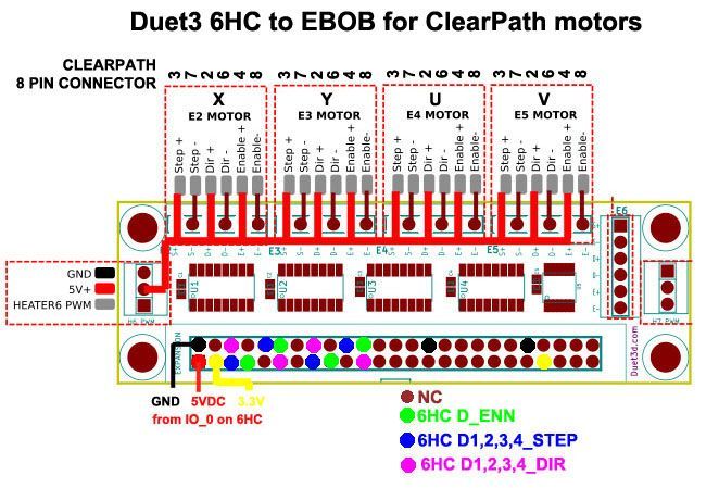
Only X and Y are connected.
-
OK, looking in the files and seeing that all the home moves move the Z axis first means that Z moving first when doing a x or y homing is not a problem. So now to figure out why the clearpath motors are not moving and the chamer temp is not reading correctly.
-
@coseng They are not moving because I have not turned the 5V output to it on! Is there a command to do this through the web control?
-
@dc42 To turn IO_3_out on to 5V, do I need to define it as a fan then turn the fan on at 100%?
-
@dc42 I'm a stumped and at an impasse if you can spare a little time to help. Everything works but the chamber temp sensors (2 PT1000 in series) still reads 2000C and I can't get the X or Y motor (Driver 1/2) to move through my roach wired BOB arrangement. Z moves fine through Driver 0. I've triple checked the roach wiring and it matches this 'schematic':
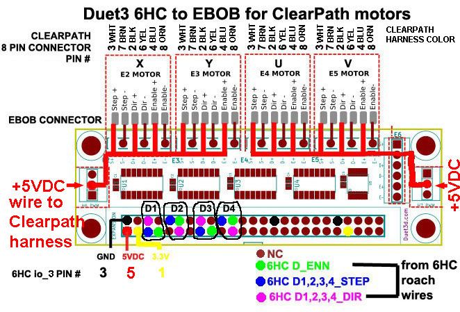
I have the 5VDC to the ClearPath's (+) inputs wired externally to the connector thought the 5VDC pin on the 3 pin connector. This allowed me to test the polarity as you indicated in your previous post: 'If you are using single ended 5V drive, then connect ENA+ of your servo to +5V, and ENA- to either Enable+ or Enable- on the EBOB, whichever gives the correct polarity.' Enable- ended up working.
The motors are both enabled (a status LED on the motor body is in the 'enabled and waiting for a move command' state). But I can't get motion with the Clearpath's (-) step and direction lines connected to either BOB connector's polarity. See image.

I'm not sure if I should try swapping the clearpath lines around so +5V goes to brn/yel/ora instead of whi/blk/blu.
Any suggestions are appreciated. Here is the config.g file:
; Configuration file for Duet 3 (firmware version 3.3)
; executed by the firmware on start-up
;
; generated by RepRapFirmware Configuration Tool v3.3.10 on Thu Apr 14 2022 23:29:28 GMT-0400 (Eastern Daylight Time); General preferences
M575 P1 S1 B57600 ; enable support for PanelDue
G90 ; send absolute coordinates...
M83 ; ...but relative extruder moves
M550 P"hyperprinter" ; set printer name
M669 K1 ; select CoreXY mode
M564 H0 ; allow moves before homing; Wait a moment for the CAN expansion boards to start
G4 S2; Network
M552 P192.168.2.1 S1 ; enable network and set IP address
M553 P255.255.255.0 ; set netmask
M554 P192.168.2.20 ; set gateway
M586 P0 S1 ; enable HTTP
M586 P1 S0 ; disable FTP
M586 P2 S0 ; disable Telnet; Drives
M569 P0.1 S1 ; physical drive 0.1 goes forwards
M569 P0.2 S1 ; physical drive 0.2 goes forwards
M569 P0.0 S1 ; physical drive 0.0 goes forwards
M569 P121.0 S1 ; physical drive 121.0 goes forwards
M584 X0.1 Y0.2 Z0.0 E121.0 ; set drive mapping
M350 X32 Y32 Z8 E16 I1 ; configure microstepping with interpolation
M92 X56.14 Y56.14 Z320.00 E837.00 ; set steps per mm
M566 X100.00 Y100.00 Z60.00 E120.00 ; set maximum instantaneous speed changes (mm/min)
M203 X2000.00 Y2000.00 Z1000.00 E1200.00 ; set maximum speeds (mm/min)
M201 X50.00 Y50.00 Z20.00 E250.00 ; set accelerations (mm/s^2)
M906 X300 Y300 Z3900 E1500 I30 ; set motor currents (mA) and motor idle factor in per cent
M84 S20 ; Set idle timeout; Axis Limits
M208 X-320 Y-290 Z0 S1 ; set axis minima
M208 X320 Y290 Z950 S0 ; set axis maxima; Endstops
M574 X1 S1 P"121.io2.in" ; configure switch-type (e.g. microswitch) endstop for low end on X via pin 121.io2.in
M574 Y1 S1 P"io1.in" ; configure switch-type (e.g. microswitch) endstop for low end on Y via pin io1.in
M574 Z1 S2 ; configure Z-probe endstop for low end on Z; Z-Probe
M950 S0 C"121.io0.out" ; create servo pin 0 for BLTouch
M558 P9 C"121.io0.in" H5 F120 T6000 ; set Z probe type to bltouch and the dive height + speeds
G31 P500 X0 Y0 Z2.5 ; set Z probe trigger value, offset and trigger height
M557 X-300:300 Y-250:250 S100 ; define mesh grid; Heaters
M308 S0 P"temp0" Y"pt1000" ; configure sensor 0 as PT1000 on pin temp0
M950 H0 C"out0" T0 ; create bed heater output on out0 and map it to sensor 0
M307 H0 B0 S1.00 ; disable bang-bang mode for the bed heater and set PWM limit
M140 H0 ; map heated bed to heater 0
M143 H0 S120 ; set temperature limit for heater 0 to 120C
M308 S1 P"temp1" Y"pt1000" ; configure sensor 1 as PT1000 on pin temp1
M950 H1 C"out1" T1 ; create chamber heater output on out1 and map it to sensor 1
M307 H1 B0 S1.00 ; disable bang-bang mode for the chamber heater and set PWM limit
M141 H1 ; map chamber to heater 1
M143 H1 S150 ; set temperature limit for heater 1 to 150C
M308 S2 P"121.temp0" Y"pt1000" ; configure sensor 2 as PT1000 on pin 121.temp0
M950 H2 C"121.out0" T2 ; create nozzle heater output on 121.out0 and map it to sensor 2
M307 H2 B0 S1.00 ; disable bang-bang mode for heater and set PWM limit
M143 H2 S320 ; set temperature limit for heater 2 to 320C; Fans
M950 F0 C"out4" Q500 ; create fan 0 on pin out4 and set its frequency
M106 P0 C"Chamber 1" S1 H-1 ; set fan 0 name and value. Thermostatic control is turned off
M950 F1 C"out5" Q500 ; create fan 1 on pin out5 and set its frequency
M106 P1 C"Chamber 2" S1 H-1 ; set fan 1 name and value. Thermostatic control is turned off
M950 F2 C"121.out2" Q500 ; create fan 2 on pin 121.out2 and set its frequency
M106 P2 C"XY Extruder" S1 H-1 ; set fan 2 name and value. Thermostatic control is turned off
M950 F3 C"out7" Q500 ; create fan 3 on pin out7 and set its frequency
M106 P3 C"Water Cooler" S1 H-1 ; set fan 3 name and value. Thermostatic control is turned off; Tools
M563 P0 S"xyhead" D0 H2 F2 ; define tool 0
G10 P0 X0 Y0 Z0 ; set tool 0 axis offsets
G10 P0 R0 S0 ; set initial tool 0 active and standby temperatures to 0C; Custom settings
M950 D1 C"spi.cs0+spi.cs2"Thanks.
-
@coseng you need to use M569 commands with T parameters to lengthen the step pulse timing for external drivers. See https://docs.duet3d.com/en/User_manual/Connecting_hardware/Motors_connecting_external#configuring-the-step-timing.
Duet WiFi hardware designer and firmware engineer
Please do not ask me for Duet support via PM or email, use the forum
http://www.escher3d.com, https://miscsolutions.wordpress.com -
@dc42 Yes, that did it, thanks! The Clearpath say .750us step pulse width minimum, so I used a setting of T2 to be safe. Now I need to so some servo tuning with Tecnik then can start printing! Finally!
Thanks to the forum for all the help so far. And to the Duet3D crew for providing a great product and better customer support than most large companies do!
-
Progress! All the axes work and no more errors. And yes, thermistors for the chamber temp sensor. I have not done the thermal tuning for any of the heaters yet, but am expecting the chamber to take a while. Are there timeouts? I can't imagine the chamber coming up to temp quickly.
The from an aural perspective, the clearpath motors are light years ahead of steppers. Compared to the steppered Z axis, they are fast and quiet, and with the long belt runs (about 3ft.) there are no problems with belt span weirdness from really slow moves to nearly 2000ipm/0.9mps rapids. Yes, 2000ipm, that is not an extra zero. I know that it will never print at those speeds, but is nice to know that there is plenty of torque to spare and that the mechanical structure has the stiffness to deal with large acceleration forces. I was surprised that the bellows was not a limiting factor. I had Tom Tullar from Teknic remotely tune the motor parameters and he was very happy with the results, with a very small following error even during accelerations. The software is pretty awesome, their diagnostic oscilloscope feature is very useful and showed very good axis alignment by having a consistent torque requirement along the entire axis length.
Here's a short video of some motion:
https://youtube.com/shorts/0DkGP00Besg?feature=share
I am really impressed with the overall quality of entire the Duet ecosystem. The hardware,firmware, software, and user support were all top quality. It is not often that I can't find something that could be improved, but this is one of those times! It makes me want to build more stuff with it!
Now on to getting it hot and printing!
-
OK, sorry about the drop out there, but had to drive from NJ to Portland, OR to have the bike this is all about at a show, the One Moto show. The show was fun, the drive sucked, but for your viewing pleasure here's a shot of the bike, sans the bodywork that this printer will print.
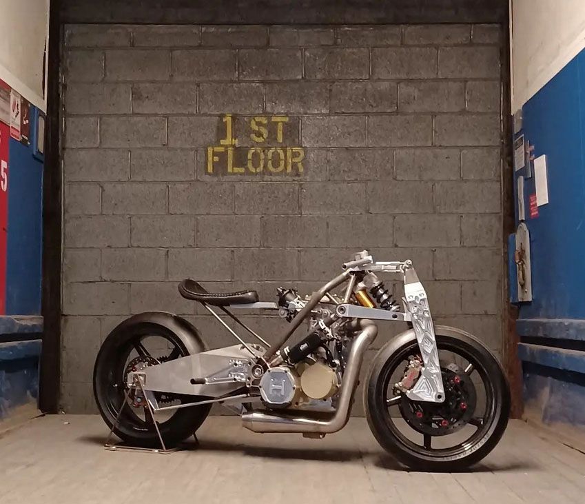
Lots of other 3d printing in this baby. The first 8" of the exhaust was DMLS printed in 316 stainless steel. The swingarm was sand cast in A356 aluminum in a mold that was printed directly in sand by humtown.com. Same goes for the engine side covers and oil sump, but they are cast in magnesium. The steel chassis lugs were FDM printed in PolyCast filament then investment cast in 4130 steel. Last but not least, the oil cooler mounting brackets were printed on my Anycubic MonoX in Siraya's high temp white resin.
-
OK, plastic has been extruded! Got the alignment good enough, then did some thermal tuning, and got that good enough, then jumped right into printing and it printed! For a little while, at least.

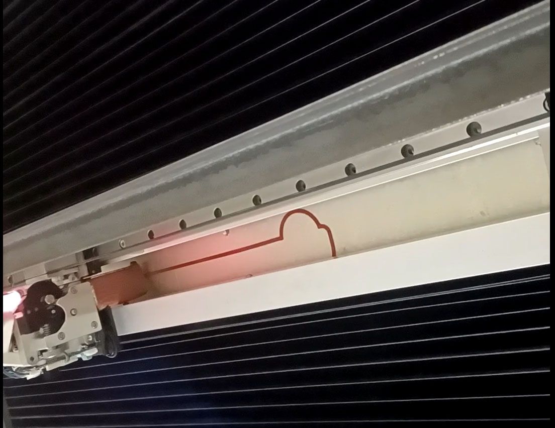
After the first layer, the filament jammed at the spool. The feed entry from the spool dug into the spool and resulted in too much friction for the extruder to overcome.

and

The spool is mounted on bearings and on its own can turn very freely. Any suggestions on how to prevent this from happening? The printer could use an entire 10kg spool in one print, so these problams can waste a lot of time and material. Any suggestions are greatly appreciated!