Mesh bed leveling - STL based probe points
-
Hi all,
this post is a sort of shared brainstorming, while considering the importance of the Mesh Bed Leveling procedure in obtaining quality prints.It's true, using a rectangular probe grid for any kind of objects will never produce an exaggerated amount of wasted probe points.
Anyway often I find myself printing thin STL on large print area: imagine a ribbon object, like a 2 wall thick serpentine extending on a 800x400mm surface, wouldn't it be efficient probing just the path of the STL/nozzle instead of massive probing (ex. 400 points) the entire print area?
Often I print honeycomb structures that are very large (ex. 700x400mm), but composed by hollow cells that have 2 o 3 perimeters walls.
I admit that in situations like these it would be not so easy to identify the right probe points: probing the entire tracks will probably produce a massive number of points, but maybe it would be nice to let the software choose points that are truly affected by nozzle print pass.Waiting to hear you about that
")
Thank you!3D Printing new Applications Researcher.
-
Interesting idea.
I have beds that benefit from using a 400 point grid but it takes a while to generate the height map for that.
I have found that I can generate the height map once and use it for all subsequent prints.
Frederick
-
@3dreamer yes, people have been doing that for a while
")
https://forum.duet3d.com/topic/25882/only-probe-where-printed-solution-here
Main drawback is that recreating a mesh before every printer is very time consuming, but that might be outweighed in your case.
Option two is to create heightmaps of certain areas of the bed and save them with different names, then you can just load the right one for each print (granted its less automatic)E3D TC with D3Mini and Toolboards.
Home-built CoreXY, Duet Wifi, Chimera direct drive, 2x BMG, 300x300x300 build volume
i3 clone with a bunch of mods -
@3dreamer A mesh is not meant to be associated with a print but with the printer. It can compensate small variations in the bed’s flatness, but it will never help with sharp bumps, holes or other damages - that’s what I associate with the request for more (or better fitting) probing points.
As @fcwilt states, a grid is typically generated once and used often - maybe you want to provide multiple grids for different bed temperatures. Given the notorious inaccuracy of our mechanics and most probes, it is better to spend some time with the careful generation of a sound mesh instead of hastily producing grids on the fly.
Of course, we have to make sure that the bed is levelled properly before we apply the mesh - it’s a misuse to take the grid as a means to get rid of levelling the bed.
-
@engikeneer
Hi all and thanks for your kind replies!I'm sorry, I didn't explain myself well: I've been using print-tailored probing grid for a long time, ex. using, in PrusaSlicer, the instruction:
M557 X[first_layer_print_min_0]:[first_layer_print_max_0] Y[first_layer_print_min_1]:[first_layer_print_max_1] Px:yWhat I really meant is about probing points that follow the nozzle path of the first layer! While printing a ribbon-like spiral you will obtain, for example, a spiral probe map!
3D Printing new Applications Researcher.
-
@infiniteloop said in Mesh bed leveling - STL based probe points:
Of course, we have to make sure that the bed is levelled properly before we apply the mesh - it’s a misuse to take the grid as a means to get rid of levelling the bed.
Sometimes, while the bed is properly levelled, there are still local roughness that can't be properly mapped by a grid, so why G29 can't it mov adapt the Z height in those points?
Imagine printing on substrates like wooden boards, fabrics, wavy surfaces, eg.3D Printing new Applications Researcher.
-
@3dreamer ah I see. I guess then the first step would be to come up with a heightmap system that isn't based on a regular and rectangular grid. It'll certainly require a more complex interpolation method. If 441 points is already the memory limit, I also wonder how much you'll be able to improve the compensated amount by...?
-
@3dreamer said in Mesh bed leveling - STL based probe points:
Imagine printing on substrates like wooden boards, fabrics, wavy surfaces, eg.
That's definitely a task quite different from what our printers are supposed to do. Something like terrain following? Interesting concept, but to do it right, you have to measure Z in situ, i.e. while printing. This should well be possible with the Duet (and a proper sensor), the real question is: how do you tell your slicer? Wavy surfaces are a concept he doesn't understand.
-
@engikeneer said in Mesh bed leveling - STL based probe points:
I guess then the first step would be to come up with a heightmap system that isn't based on a regular and rectangular grid.
That's it!
@infiniteloop said in Mesh bed leveling - STL based probe points:
That's definitely a task quite different from what our printers are supposed to do. Something like terrain following? Interesting concept, but to do it right, you have to measure Z in situ, i.e. while printing. This should well be possible with the Duet (and a proper sensor), the real question is: how do you tell your slicer? Wavy surfaces are a concept he doesn't understand.
Yes, true terrain following!
Isn't that what G29 is supposed to do, after all?You would also map the surface with a laser or a sort of little odometer, mapping the entire print surface or just the path (G1 instructions) of the first layer, obviously with precision electronic due to sampling needs.
Slicers? Where we're going, we don't need slicers.
Apart from funny quotes, ideally the slicer should stay in the dark about what will happen during print process, because the firmware itself will take care of adjusting the Z position while printing.This discussion is intriguing
-
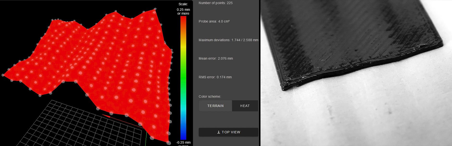
The attached image show a small 20x20 mm TPU rectangle printed on the wavy surface of a cardboard, using a 225 point mesh grid.
While printing I noticed the Z axis responding fast in order to follow the wavy surface, so I think that all the discussed matter should concerns only a firmware/math solutions.
It's all about how to manage the probeb points, letting the Z axis work to maintain the correct nozzle-bed distance when the nozzle pass over the probeb point, freeing ourself from a mandatory rectangular grid!
So, for example, while printing a thin lattice you will be able to:
- Achieve an high density map just of the first-layer footprint;
- Better follow the surface roughness thanks to a "surgical precision" probing, avoiding wasting probe points.
-
Perhaps you should first determine if the current approaches to the problem of uneven bed surface are inadequate for the majority of users.
You may be trying to solve a problem that is mostly theoretical.
If I were tasked with solving this problem I would focus on the possibility of creating a device which would allow measuring nozzle-to-bed distance in real-time and dispense with the whole array of points approach.
Frederick