Automatic Tool Offset (XYZ) for Syringe Printer?
-
I've turned an E3D Toolchanger into a Syringe dispensing printer. I'm dispensing materials with viscosities similar to silicone caulking.
One major difference between my printer and an FFF printer is that nozzle changes are frequent - typically before each print to ensure reliable dispensing.
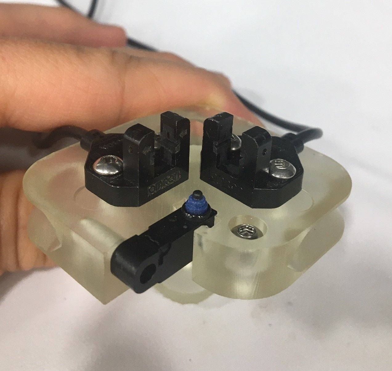
Does anyone think automatic tool offsets can be done using optical endstops for X, Y and a physical endstop for Z? I have several of these, which I've confirmed to work on 3.3V:
https://www.ia.omron.com/product/item/2263/Z is the most straight forward, since I can just mount a switch somewhere on the buildplate and have the tool tip actuate it.
For X and Y, one commercial syringe printer uses a "LASER Beam Break" sensor. The nozzle is automatically jogged to break the x-axis sensor beam, same for the y-axis, and then the nozzle center is calculated. This gave me the idea of using the optical endstops.
For implementing in firmware, is M585 a good place for me to start?
https://duet3d.dozuki.com/Wiki/Gcode#Section_M585_Probe_ToolHere's how the syringe tips look:

I've tried TAMV, and I use it for my FDM printer, but it proved to be unreliable for the syringe tips which are different sizes and colors, and the camera I use can't detect the nozzle center reliably.
Firmware: V3.3 on Duet 2 Ethernet
I appreciate any feedback!
-
@hebigt said in Automatic Tool Offset (XYZ) for Syringe Printer?:
For implementing in firmware, is M585 a good place for me to start?
https://duet3d.dozuki.com/Wiki/Gcode#Section_M585_Probe_ToolThat sounds like the best place to start. Though I think in CNC applications they are using a ring shaped metallic sensor that will trip the switch when it makes contact with the conductive tool tip. Not sure how it would work with multiple switches for X and Y.
Is there much X/Y variation between tips once they are mounted?
-
@phaedrux Thanks for the reply. I'll give this a try and update with what happens.
Some of the tips are straight, but others deviate across their length by 1mm, sometimes more or less. But they are inexpensive, which is a plus.
-
hi @hebigt!
Having recently done this on a multi-material syringe extruder, I can confirm that M585 is a method that works. Originally, we started down the path with optical sensors but couldn't find something that fit the budget (as cheap and quick as possible).
Our solution:
- Use a USB microscope , similar to TAMV in that it is in the upright position, and hook it up to a PC.
- Take the usb feed and overlay a crosshair on it.
- Using a macro, step over to the center of T0's needle and store X0, Y0 using G10
- Macro should move the nominal amount between needles (calculate in CAD or eyeball it so T1 is in the camera's view)
- Step into the center of T1's needle and store that with G10 as well.
I've seen better than 20um accuracy with this method. If the needle isn't straight, either bend it, reseat it on the luer, or toss it for another one.
For Z, as mentioned by @Phaedrux, we used a simple block of aluminum and alligator clip to the needle to make a conductive sensor. Do the Z before the XY tool offset to ensure both tools are on the same plane.
Happy to dive in a little deeper but unfortunately can't share pictures of our setup.
-
Great to hear from you and thanks for sharing your experience with it. The method you described is what I ended up doing, and it has worked well for us. I still want to try the optical endstop + M585 route when I find some time. I salvaged the optical sensors from a decommissioned piece of equipment.
I even designed a mount for all three sensors. No Idea if it will work, though. Especially with the very small contact point on the z-axis switch in the middle.Thanks again!
-
Update:
The automatic 'offsetting' for the Tool's syringe tip length (Z offset) works very reliably.
The X and Y offset has some issues but I think it can be tweaked to make it work.
M585 works, but not in the way I expected. It sets the offset to (starting position - ending position) + expected distance.
Videos:
I ended up using meta-commands to get this far, and I think it could be done with G30 (for Z-offset) and G1 H4 commands instead of using M585.
-
 undefined HebigT marked this topic as a question
-
undefined HebigT marked this topic as a regular topic
-
@hebigt
Hey
Could you share some information about the meta command?I'm also want to have a tool endstop but couldn't find out which commands I have to use, so that the offset applies automatically.
Thanks a lot!!
Richard -
@gruna-studio
Hey, I used the meta commands outlined here:
https://docs.duet3d.com/en/User_manual/Reference/Gcode_meta_commands
and the object model ( the object model plugin for DWC was very helpful)
For the most part, I just needed to reference the position of an axis once it hit the endstop, initialize a variable for it, and then use that variable later on.
For example, for the z-axis, the printer first homes to the buildplate with a microswitch to set zero, but each tool has a syringe tip which sits below that microswitch. Also, the "Z-axis offset switch" is mounted on that printed part which makes it sit some unknown distance above the buildplate.
I figured out that distance by jogging the tool until it actuated the switch (M119 to check endstop status), and then moved the tool off the switch and measured down to the buildplate.
The macro I use does this:
- Home the printer
- Define the new Z-axis endstop
- Pick up the tool
- move the tool over the switch
- Move the Z-axis until the syringe tip hits the switch (M585)
- Store the current position as a variable
- Do some simple math to figure out how far down the syringe tip is from the Z-axis homing switch (not the offset switch), using the measured height of the switch+mount and the known current position.
- Assign that new value to the offset for that tool (G10...)
- Save the offset to config-override.g with M500
One tip: Use M114 in the console to view the current axis position with more decimals places.
-
@hebigt
Thanks a lot for this detailed description!!
I'll try it out ASAP.
That will make my workflow a lot better.
Edit: I've never used meta data's before. Is there an example for it concerning the tool switch?For the x and z axis I'll install a camera cased automatic offset.
I'll open a new thread when this happendRichard
-
@gruna-studio
What type of machine are you using? Printer or CNC or something else?
Unfortunately, I can't share the macro I wrote, but I promise it's nothing special.
For meta commands I searched the forum for examples and then practiced using the console in DWC.
That Meta command link is very helpful. And here's an explanation of the object model:
https://duet3d.dozuki.com/Wiki/Object_Model_of_RepRapFirmwareExamples with syntax:
; Initialize a variable

var offset_thickness = 14 ;Units are mm

; Initialize a variable to some existing value in the object model, such as the current position of the z-axis

var z_position = move.axis[2].machinePosition ; The 2 gives the index # for the z-axis on my printer

; Write an existing variable to the console

echo var.z_position


;  Update the tool offset with an existing variable

G10 P0 X0 Y0 Z{var.z_position}
Conditional statements are also possible
; if statement to alert the machine operator if the tool offset is unusually small if tools[0].offsets[2] > -20.0 M291 P"The Z-offset for Tool 0 is smaller than expected. Ensure the syringe barrel is properly seated in the mount" R"Warning!" S1 T0 -
This post is deleted! -
@hebigt
I made a new account because its going professional, now.Thanks for your fast reply. I think I'll work it out. This short example is quiet helpful!!
I have two custom toolchanger with a 103x103x103cm built volume with
lovely closed loop steppers. -
-
Short question... till I have more time for this meta commands, I´ll work with M585, but I have alwayyys the problem, that Duet could´nt find the new zstop.
Please take a quick look where my mistake is.
Thanlks; Configuration file for Duet 3 (firmware version 3) ; executed by the firmware on start-up ; ; generated by RepRapFirmware Configuration Tool v3.2.3 on Mon Aug 02 2021 16:15:35 GMT+0200 (Mitteleuropäische Sommerzeit) ; General preferences G90 ; send absolute coordinates... M83 ; ...but relative extruder moves M550 P"Duet 3" ; set printer name M552 s1 M550 P"Black Flamingo" M587 S"AndroidAPebc3_EXT" P"hhhhhhhh" G4 S4 M574 C1 S3 M574 C0 Z0 M915 P0.5 C S0 F0 R1 ; Drives ;closed loop M569.1 P20.0 T2 C5 R69 I0 D0 H10 ; Configure the 1HCL board at CAN address.20quadrature encoder 128 steps/motor full M569.1 P21.0 T2 C5 R69 I0 D0 H10 ; Configure the 1HCL board at CAN address.21quadrature encoder 128 steps/motor full step. M569.1 P30.0 T2 C5 R100 I0 D0 H10 ; Configure the 1HCL board at CAN address.21quadrature encoder 128 steps/motor full step. M569 P20.0 D4 S0 ; Configure the motor on the 1HCL at can address 20 as being in closed-loop drive mode (D4) and not reversed (S1) M569 P21.0 D4 S1 ; Configure the motor on the 1HCL at can address 21 as being in closed-loop drive mode (D4) and not reversed (S1) M569 P30.0 D4 S0 ; Configure the motor on the 1HCL at can address 21 as being in closed-loop drive mode (D4) and not reversed (S1) Other drives; open loop; M569 P0.0 S0 ; physical drive 0.0 goes forwards M569 P0.1 S0 ; physical drive 0.2 goes forwards M569 P0.2 S0 ; physical drive 0.2 goes forwards M569 P0.3 S0 M569 P0.5 S0 M569 P100.0 S1 ; physical drive 0.2 goes forwards M569 P110.0 S1 ; physical drive 0.2 goes forwards M584 X30.0 Y20.0:21.0 Z0.0:0.1:0.2:0.3 C0.5 E100.0:110.0 ; set drive mapping M350 X32 Y32 Z128 E16:16:16 I1 ; configure microstepping with interpolation M92 X80.00 Y80.00 Z5120.00 C91.022 E409.00:409.00:409.00 ; set steps per mm M566 X600.00 Y600.00 Z60.00 C3000 E1000.00:1000.00:600.00 ; set maximum instantaneous speed changes (mm/min) M203 X12000.00 Y12000.00 Z500.00 C10000 E6000.00:6000.00:6000.00 ; set maximum speeds (mm/min) M201 X1600.00 Y1600.00 Z500.00 C550 E2500.00:2500.00 ; set accelerations (mm/s^2) M906 X1700 Y1700 Z2300:2300:2300:2300 C600 E1000:1000 I30 ; set motor currents (mA) and motor idle factor in per cent M84 S300 ; Set idle timeout M671 X-140:-140:990:990 Y-140:990:990:-140 S20 ; leadscrews at front left1 and n´back2. back rigth3 and front4 ; Axis Limits M208 X0 Y-100 Z0 S1 ; set axis minima M208 X860 Y860 Z850 S0 ; set axis maxima ; Endstops M574 X2 S1 P"^30.io1.in" ; configure active-high endstop for high end on X via pin ^io3.in M574 Y2 S1 P"^20.io1.in+21.io1.in" ; configure active-high endstop for high end on Y via pin ^io1.in ; Z probe M558 P5 C"0.io1.in" H8 F2000 I0 T5000 ; Set Z probe type to switch, the axes for which it is used and the dive height + speeds G31 P200 X0 Y0 Z0 ; Set Z probe trigger value, offset and trigger height; Z probe M556 S50 X0 Y0 Z0 ; set orthogonal axis compensation parameters M557 X50:700 Y50:700 S65 ; define mesh grid ;Tool Switch M558 K1 P5 C"0.io2.in" H8 F2000 I0 T5000 ; create probe #1 for use with M585, active low G31 P200 X0 Y0 Z0 ; Heaters M308 S0 P"temp0" Y"thermistor" T100000 B4138 ; configure sensor 0 as thermistor on pin temp0 M950 H0 C"out0" T0 ; create bed heater output on out0 and map it to sensor 0 M307 H0 B0 R0.243 C586.2 D33.87 S1.00 V0 ; disable bang-bang mode for the bed heater and set PWM limit M140 H0 M143 H0 S120 M308 S1 P"100.temp0" Y"thermistor" T100000 B4138 ; configure sensor 1 as PT1000 on pin 121.temp0 M950 H1 C"100.out0" T1 ; create nozzle heater output on out1 and map it to sensor 1 M307 H1 B0 R1.553 C487.8 D10.35 S1.00 V0 ; disable bang-bang mode for heater and set PWM limit M143 H1 S250 M308 S2 P"110.temp0" Y"thermistor" T100000 B4138 ; configure sensor 2 as PT1000 on pin 121.temp0 M950 H2 C"110.out0" T2 ; create nozzle heater output on out1 and map it to sensor 2 M307 H2 B0 R1.553 C487.8 D10.35 S1.00 V0 ; disable bang-bang mode for heater and set PWM limit M143 H2 S250 ; set temperature limit for heater 1 to 250C ; set temperature limit for heater 1 to 250C ; Fans M950 F0 C"100.out1" Q500 ; create fan 0 on pin 100.out1 and set its frequency M106 P0 S0 H-1 ; set fan 0 value. Thermostatic control is turned off M563 P0 D0 H1 ; tool uses extruder 0, heater 1 M950 F1 C"100.out2" Q500 ; create fan 1 on pin 100.out2 and set its frequency M106 P1 S1 H1 T45 ; set fan 1 value. Thermostatic control is turned on M563 P0 D0 H1 F1 ; tool uses extruder 0, heater 1 M950 F2 C"110.out1" Q500 ; create fan 2 on pin 101.out1 and set its frequency M106 P2 S1 H-1 ; set fan 2 value. Thermostatic control is turned off M563 P1 D1 H2 ; tool uses extruder 0, heater 2 M950 F3 C"110.out2" Q500 ; create fan 3 on pin 101.out2 and set its frequency M106 P3 S1 H2 T45 ; set fan 3 value. Thermostatic control is turned on M563 P1 D1 H2 F2 ; tool uses extruder 1, heater 2 ; Magnete M950 F8 C"0.out8" Q500 CMagnet0 ; create magnet 0 on pin out9 and set its frequency M106 P0 S0 H-1 ; set fan 0 value. Thermostatic control is turned off M950 F9 C"0.out7" Q500 CMagnet1 ; create magnet 0 on pin out9 and set its frequency M106 P0 S0 H-1 ; set fan 0 value. Thermostatic control is turned off M950 F10 C"21.out0" Q500 CMagnet2 ; create magnet 0 on pin out9 and set its frequency M106 P0 S0 H-1 ; set fan 0 value. Thermostatic control is turned off M950 F11 C"21.out1" Q500 CMagnet3 ; create magnet 0 on pin out9 and set its frequency M106 P0 S0 H-1 ; set fan 0 value. Thermostatic control is turned off ; Tools M563 P0 D0 H1 F0 ; define tool 0 G10 P0 X-9 Y-39 Z-3.65 ; set initial tool 0 active and standby temperatures to 0C G10 P0 R0 S0 M563 P1 D1 H2 F2 ; define tool 1 ; set initial tool 0 active and standby temperatures to 0C G10 P1 X-8.4 Y-39.2 Z-4 G10 P1 R0 S0 ; Miscellaneous M911 S10 R11 P"M913 X0 Y0 G91 M83 G1 Z3 E-5 F1000" ; set voltage thresholds and actions to run on power lossG1 X660.2 Y100 Z100 F3000 G1 X660.2 Y-60.1 F3000 M585 Z120 F600 P1 S1
thanks a lot!
-
I see you have some endstop definitions in your config.g (M574), but I don't immediately see where you are defining the new Zstop - are you trying to set it up as you would a z-probe?
In my approach, I just set up the new "z-stop" as an additional endstop.
M574 Z0 P"zstop" S1Note that I'm using Firmware 3.4 and a Duet 2.
-
 undefined IndeX4D referenced this topic
-
thanks a lot for your fast reply!
you´re doing the most effizient posts
-
I think I can close out this thread now
Both the Automatic Z and XY offset are working.
For XY offsets (using the optical endstops) I had to probe each side of the syringe tip - i.e. probe the tip on both sides in the x direction, probe both sides in the y-direction... I think this is how some dual extruder FDM printers set the XY offsets.
I used gcode meta commands to query current machine positions and then referenced those values later on. Every now and then I used an IF statement to check whether a variable already exists.
I used a USB microscope to check the syringe tip alignment across tools and it looks good.
For anyone coming across this in the future, I used Fisnar tapered tips and blunt-end steel tips. I found that some plastic tapered tips didn't work well with the optical endstops. (Blue, pink, orange colored tips might be more transparent to gallium-arsenide LED?). The steel, blunt-end tips work great.
-
undefined HebigT marked this topic as a question
-
undefined HebigT has marked this topic as solved
-
undefined HebigT referenced this topic
-
undefined HebigT referenced this topic