optical ABL for 6HC OPB 880T51
-
Hi,
This swap is for a heated chamber BL touch is not gonna happen and i want to use a optical 4 wire end stop (OPB- 880T51) and would like to use this for ABL do you know how i would set it up on the 6HC best?
There are side stops that will deploy and retract the mechanical pin interaction with the optical switch from in use to not.
red,blk,grn,white <<<<<<<<<<>>>to 6HC pin#?
rd,bk,gn,we2 anode and two cathode
it is the stock switch for the z foam in a stratasys 768
i will just have to insert the G code for where to travel to the bumps to deploy and retract when done! (one on each side)
Or does the Antclabs BL touch 8/32 bit have the temprature screw to get me to not go into OT? it is possible but close to OT so Optical is my choice just not sure if this one has the adjustment or if i should even care and just use optical
i am using 2 wire optical stops for the homing...to 80C chamber no problem
anyother ideas to ABL in Chambers please feel free
-
What is the actual pinout for the optical switch? Do you have a data sheet?
It's not clear to me what the deploy and retract setup you talk about looks like.
Maybe something like a Euclid or klicky probe would work for your needs? Pick up and stow away when done?
-
@phaedrux it is a pick up and stow away it has an arm to deploy and retract from hitting stationary tabs behind the bed one on each side one to deploy and one to stow
the tabs are behind the bed and need to hit the deploy tab before and retract tab after the probe and would need the same for a full home all
any examples in giving me an idea what this would look like in a config so on would help me to set and understand them better so i can work with the sequence and order and adjust the locations needed i have been spoiled by RRF and no little Codes and just read backwards usually
-
@phaedrux https://datasheetz.com/data/Sensors, Transducers/Optical - Photointerrupters - Slot Type - Transistor Output/OPB880T51Z-datasheetz.html
-
@rexx said in optical ABL for 6HC OPB 880T51:
it is a pick up and stow away it has an arm to deploy and retract from hitting stationary tabs behind the bed one on each side one to deploy and one to stow
the tabs are behind the bed and need to hit the deploy tab before and retract tab after the probe and would need the same for a full home allI'm still having a hard time visualizing what this looks like in practice, sorry.
-
@Phaedrux think of a bistable mechanism that is triggered by hitting those tabs. So the deployprobe should be a series of moves in front and then to touch the tab, and the retract probe should be a similar series of moves, just to the other tab.
-
-
exactly!
any chance you have an example for me i am new with codes by far and could use a hand -
Here is how I envision it, with a lot of assumptions you need to double and triple check on your machine. All distances are for the sake of the example and since I know nothing about your machine are just to make maths easier to explain the process.
Assuming you have left handed coordinate system with the coordinate origin at the front left, and a 250x250mm bed, with the "deploy tab" 10mm behind the bed on the left hand side, and the "retract tab" 10mm behind the bed on the right hand side. The tabs are inset 5mm from the edge of the bed on the left hand side, and 30mm from the edge of the bed on the right hand side, and the mechanism is to the left hand side of your nozzle with an X offset of 25mm and the probe actuator in line with the probe.
I assume you have a z endstop and the tab activation height is 10mm.
your
deployprobe.gwould look somewhat like this.G28 ; home all axes before deploying M400 ; clear movement queue M913 X30 Y30 ; reduce motor current for safety M208 Y0:262 ; extend Y axis for probe actuation G0 X125 Y125 Z10 F600 ; move toolhead to safe position G0 X30 ; move toolhead to trigger position X-- tab position (5) plus probe offset (25) G0 Y260 ; move toolhead to trigger position Y G0 Y220 ; back off from trigger tab G0 X150 Y125 ; move toolhead so deployed probe is at center of bed M400 ; clear movement queue M208 Y0:250 ; reset Y axis for printing M913 X100 Y100 ; reset motor currents to standard your
retractprobe.gwould look somewhat like thisM400 ; clear movement queue M913 X30 Y30 ; reduce motor current for safety M208 Y0:262 ; extend Y axis for probe actuation G0 Y125 X245 Z10 F600 ; move toolhead to trigger position X -- tab position (220) plus probe offset (25) G0 Y260 ; move toolhead to trigger position Y G0 Y220 ; back off from trigger tab G0 X150 Y125 ; move toolhead to center of bed M400 ; clear movement queue M208 Y0:250 ; reset Y axis for printing M913 X100 Y100 ; reset motor currents to standard Again, this is completely hypothetical and may or may not work for your machine.
The whole thing could be made smarter with metacommands (for example only homing if an axis is not homed), and if you have a way to check whether actuation works (for example by closing a contact that is set up as a trigger, setting a global variable depending on whether it is set or not) this could be made relatively safe. Before you blindly add code snippets, run them line by line and have a hand on the emergency stop button on every step.
-
This post is deleted! -
This post is deleted! -
@oliof
exactly what i was looking for thank you! and i understand to check my work and is only for example only so i can read backwards saving me decent time catching on faster
its not rocket science i get that but overwhelming at first and ever changing so this in is much appreciated!Cheers
-
@rexx we all started out somewhere (-:
-
@arnold_r_clark
Reguars thank you for thatthis is perfect
the new guys(me) love the little things and your help is appreciated hereshould you be interested in helping remote for compensation i would be interested in that sould you be.
and if i am stepping over the rules here i applogize and will retract if found inappropriate (DC42 and friends)
i feel i will be able to hash it out but its gonna be a long curve i would like it a bit straighter..
thank you Arnold
-
@arnold_r_clark


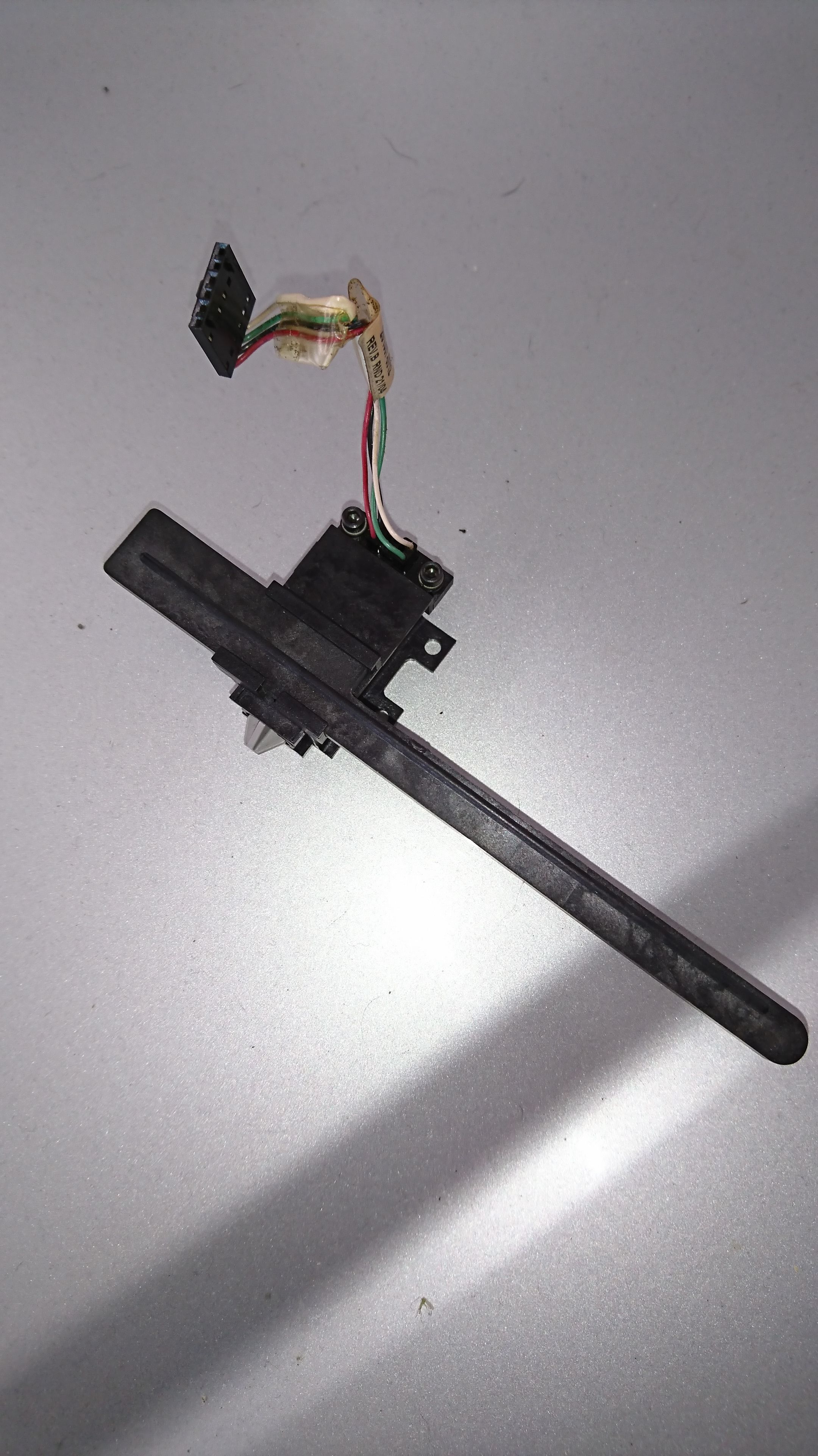
here is the abl i am using
the bar on this ABL is hit with tabs deploying the pin another tab is hit to return the probe
at the top you can see the pin to switch intersection is fixed an PCB OPTICAL will not fit this part unless i modifiy but not sure that is ideal the mounting is tiny tiny.... of course and would not fit unless i sepetate the pcb out board....hummmmthanks for your efforts
Cheers
-
@arnold_r_clark
i just re read your post to "correlation" missed that part my bad i understand to implement this and i am good....
question: does a 222 resistor and 101 come in an inline form how do you find the impedances to replicate or do you know what the values are for them OR do you think mounting this board remote is a better route
either way i get the set up now after looking at the 4 wires switch to 3 wire outs but I only thought there was one resistor needed so that 90%
thanks
-
@rexx use a meter dummy....
-
under your deployprobe.g lines 4 and 11 have : full colon yet 8 does not what does this difference mean?
if i set the reduce motor current for probing does it mean X30 y30 in the M906 means 30=300 mA each?
i have 3 nema 23 and 1 nema 17 so i think i will start at 800mA for the 17 and 1800 mA for the 23... for normal current how does the current reduction work by % or individual axis current set points?
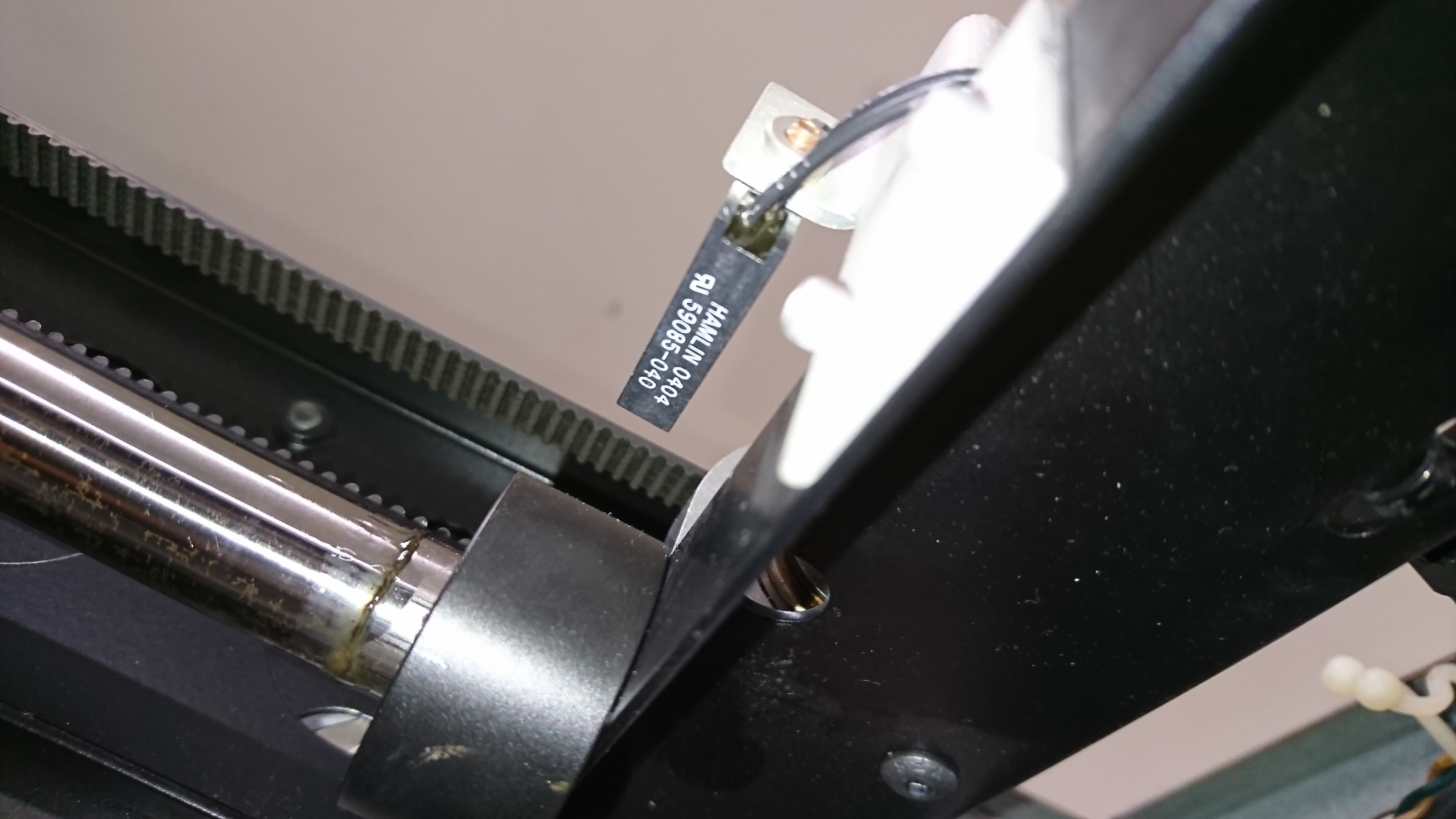
here is the 2 wire optical for xy stops they trigger with no power and a contact multi-metre setting just fine could i possibly use them like a micro switch? IO in and ground
they are hamlin 0404 (59085-040)
also noticed i think but can you momentarily go outside my X stop to deploy or do i need to move the stop so its with in the stops to deploy?
i am getting closer i can smell it and i haven't even plugged in yet
")
-
@rexx said in optical ABL for 6HC OPB 880T51:
under your deployprobe.g lines 4 and 11 have : full colon yet 8 does not what does this difference mean?
Lines 4 and 11 are M208 commands. I prefer the syntax variant where I set minima and maxima separated by a colon. Line 8 is a G0 command and the space in the example between Y and 220 is wrong. It should be
G0 Y220.if i set the reduce motor current for probing does it mean X30 y30 in the M906 means 30=300 mA each?
Good catch, that should have been M913. Sorry for this mistake! I will fix my mistakes now.
i have 3 nema 23 and 1 nema 17 so i think i will start at 800mA for the 17 and 1800 mA for the 23... for normal current how does the current reduction work by % or individual axis current set points?
With the M913 command as mentioned above.
-
so with M208 can i go outside the stops momentarily? like 10mm to deploy me ABL?
or must i have the abl inside the stops?
its a hit to deploy and stow and the stow is like 5-10mm past the stop but i could move the trigger tab to accommodate but don't want to if i dont need to.and can pass the stop slightlymy home pos is on the back right
my bed is 235x235x300
is it typical to use 0 for home or better to use closest bed corner from home as 0?reason is my home pos to the start of the bed is a bit like x30y180 if 0 is home
or am i better to use x-30y-180 for home
or should i just use ocotoprint and forget all this and baby step the numbers that way??and record...
i think my duet 2 is set home 0 bed +##
just trying to get an insight on the best approach here