Step Rate abominably low causing layer shifts.
-
@ryanrocksforever do you have timings set for each drive in M569?
-
@jay_s_uk No I do not
-
@ryanrocksforever said in Step Rate abominably low causing layer shifts.:
@fcwilt The odrive provides a graph of incoming steps, and through testing at different speeds, and therfore steps/second, I determined that at higher speeds, not as many steps were coming in as their should have been for the same amount of movement. I have not tried making the steps/mm to be a whole value yet, I am unsure whether that would make a difference.
This and your first post suggests to me that the odrive is just not reading the steps coming in when at high speeds, so is missing steps sent by the Duet and losing position. I'd suggest looking up the recommended pulse timings in the datasheet and setting the M569 command as @jay_s_uk mentions
-
@ryanrocksforever post your config.g and response to M115 for firmware version, please.
If you are not setting the T parameter of M569 for the odrive axes, where T is:
Taa:bb:cc:dd - Minimum driver step pulse width, step pulse interval, direction setup time and direction hold time, in microseconds
then the timings are probably defaulting to 'fast' timings, which may well be too fast for the odrive, particularly as speed increases. I had a quick look at the odrive documentation, but couldn't immediately see what the timings should be. Perhaps start with conservative settings of T5:5:10:10
Ian
-
@ryanrocksforever Also, the links in this thread might help: https://forum.duet3d.com/topic/23476/high-speed-printing-using-odrive
Ian
Bed-slinger - Mini5+ WiFi/1LC | RRP Fisher v1 - D2 WiFi | Polargraph - D2 WiFi | TronXY X5S - 6HC/Roto | CNC router - 6HC | Tractus3D T1250 - D2 Eth
-
@droftarts My firmware version is 3.4.0. After @jay_s_uk mentioned the M569 command I looked it up in the gcode dictionary, which led me to the max achievable step rate spreadsheet, which I had previously looked at. I also noticed the settings for The 1XD expansion, for a 600 kHz step rate which was T0:0:0, I implemented this with the hopes that it would improve the step rates for the external drivers of a Duet 3 mini 5+. I tested the Printer again, and it was no longer failing on the duets side. Now I am experiencing motor spinouts around 500 mm/s. This printer is very big and heavy, so I did not expect for that much higher. I also plan to use the printer as a CNC mill in the future. Would you know of any information on the expansion 1HCL for closed loop systems, I would be interested in parallel wiring the encoders from my motors to the duet, so I could achieve a true closed loop system. After test prints, a benchy boat, I noticed that the printer is still shifting, I intend to do more test prints, particularly ones that I can look at more to identify layer shifts. One interesting thing that I found is that when I run a movement test macro with z movement included, the top speed goes way down, and caps at 240 mm/s compared to upwards of 400 mm/s otherwise. I believe that this is being reflected in prints, by when a travel move occurs, i have mine set at 300 mm/s, the printer loses a couple steps, resulting in small layer shifts, and a gradual change in accuracy. Why? I think it is because too much bandwidth is taken up. But what do I know.
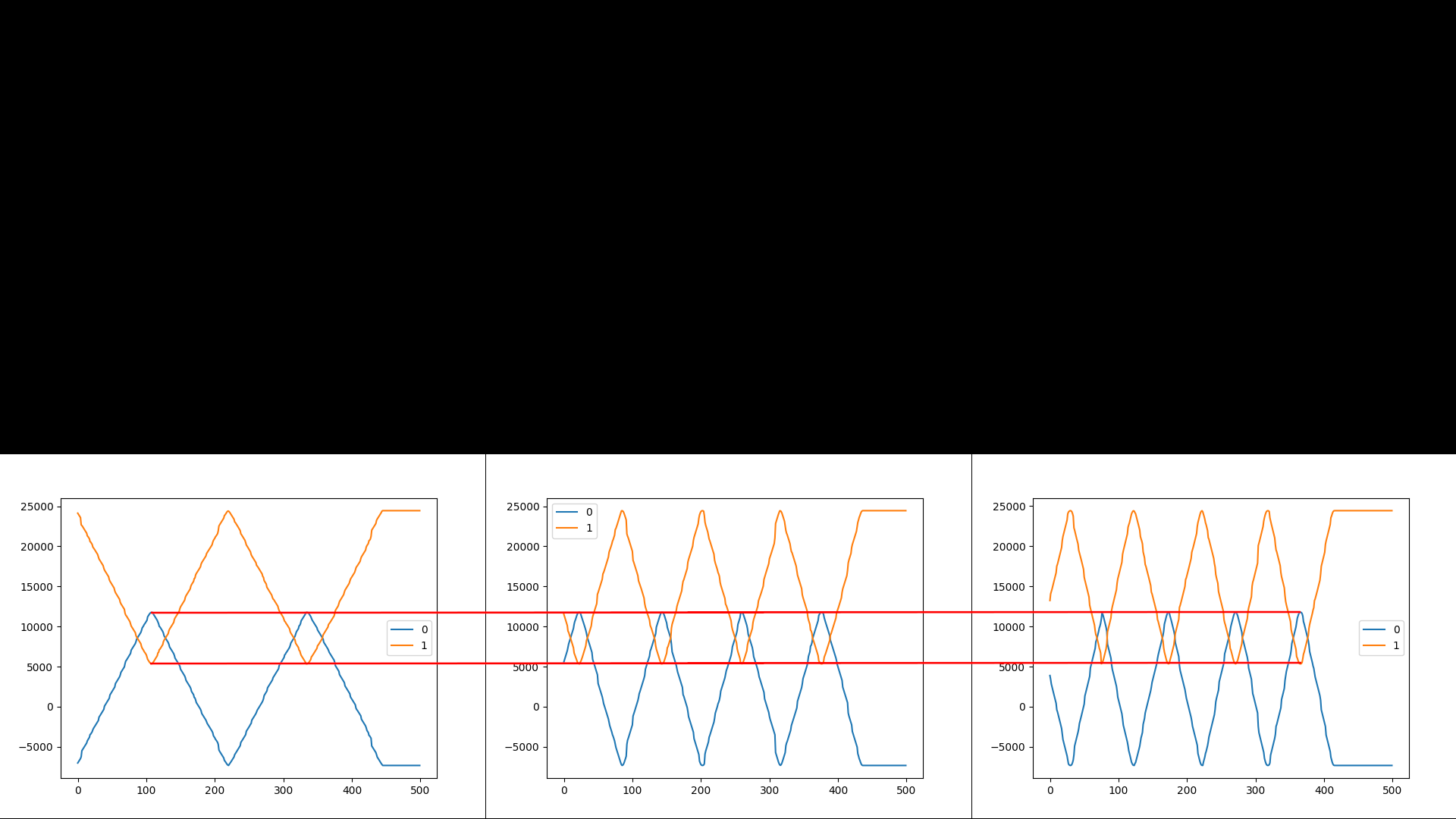
Here is an image i compiled of tests from 10k mm/min, 20k mm/min, and 25k mm/min. Y axis is steps, X is time
regarding the vez3d video, I watched it, and He uses a Klipper system to coontrol his odrive, and he does not experience layer shifts. I have a toolboard connected to a hemera on the toolhead, so it is not possible for me to switch to Klipper.
-
@ryanrocksforever external stepper driver will not work with T0:0:0:0. They have minimum timing characteristics that you must meet in order for them to recognise the steps and to to the direction changes at the right time. Look up the timing requirements in the datasheet and adjust the T parameter to match. The problem you are having is not to do with insufficient step rate, it is caused by failing to meet the timing requirements of your external drivers.
RRF never skips steps if it can't meet the requested step rate, at worst it slows down the step rate.
Have you actually calculated the step rate that you need in order to achieve 300mm/sec? It will depend on what steps/rev you have set your ODrives to use.
BTW Hangprinter version 4 uses ODrives driven by Duet 3 boards.
Duet WiFi hardware designer and firmware engineer
Please do not ask me for Duet support via PM or email, use the forum
http://www.escher3d.com, https://miscsolutions.wordpress.com -
heres the config.g for the hangprinter
; Communication and general
G21              ; Work in millimetres
G90              ; Send absolute coordinates...
M83              ; ...but relative extruder moves

; Kinematics
G4 S1                           ; Wait 1 second because expansion boards might not be ready to receive CAN signal yet.
M584 X40.0 Y41.0 Z42.0 U43.0 P4 ; map ABCD-axes to CAN addresses, and set four visible axes. Please excuse that ABCD motors are called XYZU here.
M584 E0:1:2:3:4:5               ; Regard all built in stepper drivers as extruder drives
M669 K6                         ; "This is a Hangprinter"
M669 P2000.0                    ; Printable radius (unused by Hangprinters for now)
M669 S430 T0.1                  ; Segments per second and min segment length

; Output of auto calibration script for Hangprinter
M669 A0.0:-1610.98:-131.53 B1314.22:1268.14:-121.28 C-1415.73:707.61:-121.82 D-0.00:0.01:2299.83
M666 Q0.128181 R75.546:75.659:76.128:75.192
; Explanation:
; ; M669 defines the positions of the anchors, expressed as X:Y:Z distances between a line's pivot points, when the machine is homed.
; ; M666 sets Q=spool buildup, R=spool radii (incl buildup, when homed)

M208 Z2000.00  ; set maximum Z somewhere below D anchor. See M669 ... D<number>
M208 S1 Z-10.0 ; set minimum Z

; The following values must also be in the auto calibration script for Hangprinter (if you plan to use it)
M666 U2:2:2:4         ; Mechanical advantages on ABCD
M666 O1:1:1:1         ; Number of lines per spool
M666 L20:20:20:20     ; Motor gear teeth of ABCD axes
M666 H255:255:255:255 ; Spool gear teeth of ABCD axes

; Flex compensation
M666 W1.0                 ; Mover weighs 1 kg. Set to 0 to disable flex compensation.
M666 S20000.0             ; Spring constant (rough approximation) for Garda 1.1 mm line (unit N/m).
                          ; The real value is somewhere between 20k and 100k.
                          ; Lower value gives more flex compensation.
M666 I0.0:0.0:0.0:0.0     ; Min planned force in four directions (unit N).
                          ; This is a safety limit. Should affect only exceptional/wrong moves,
                          ; for example moves outside of the reachable volume.
M666 X70.0:70.0:70.0:70.0 ; Max planned force in four directions (unit N)
                          ; This is a safety limit. Will affect moves close to
                          ; the limits of the reachable volume.
M666 T10.0                ; Desired target force (unit N).
                          ; The flex compensation algorithm aims for at least
                          ; this amount of fource in the ABC line directions at all times.
                          ; It can be thought of as a minimum pre-tension value.
                          ; It's recommended to set it around 10 times higher
                          ; than your W (mover weight in kg) value.

; Guy wire lengths. Needed for flex compenation.
; Guy wires go between spool and final line roller.
; If your spools are all mounted on the D-anchor, on the ceiling plate, then you're all good,
; and you don't need to configure M666 Y values explicitly.
; If your spools are not all on the D-anchor then you must measure guy wire
; lengths and set them here.
; If your spools are all mounted on their respective anchors, so that you have no guy wires,
; then you should configure zeroed guy wire lengths M666 Y0.0:0.0:0.0:0.0.
;M666 Y-1.0:-1.0:-1.0:-1.0

; Torque constants. These are required for reading motor forces from ODrives
; They are the same values as is configured in the ODrives themselves (8.27/330 for motors in the standard  HP4 BOM)
;M666 C0.025061:0.025061:0.025061:0.025061

; Uncomment M564 S0 if you don't want G0/G1 moves to be be limited to a software defined volume
; M564 S0

; Drives
M666 J25:25:25:25 ; Full steps per ABCD motor revolution (match with ODrives...)

M569 P0 S1 ; Drive 0 goes forwards
M569 P1 S1 ; Drive 1 goes forwards
M569 P2 S1 ; Drive 2 goes forwards
M569 P3 S1 ; Drive 3 goes forwards
M569 P4 S1 ; Drive 4 goes forwards
M569 P5 S1 ; Drive 5 goes forwards

;; Warning: On a Hangprinter, ABCD motor directions shouldn't be changed, at least not
;;          via this config.g file.
;;          They are duplicated and hard coded into the firmware
;;          to make ODrive's torque mode go the right way.
;;          Please connect BLDC wires, from left to right, looking at the board
;;          from the front, so that ODrive silk screen is readable from left to right:
;;          |---------------------------------------------------------------|
;;          |DC                                                             |
;;          |-                    ODrive                                    |
;;          |+                                                              |
;;          |                          AUX                                  |
;;          |--||---||---||------------------------------------||---||---||-|
;;             ||   ||   ||                                    ||   ||   ||
;; ALT 1:   Black, Red, Blue                                Black, Red, Blue
;; ALT 2:  Yellow, Black, Red                              Yellow, Black, Red

M569 P40.0 S1 ; Drive 40.0 (A) goes forwards
M569 P41.0 S1 ; Drive 41.0 (B) goes forwards
M569 P42.0 S0 ; Drive 42.0 (C) goes backwards
M569 P43.0 S0 ; Drive 43.0 (D) goes backwards

; Speeds and accelerations
M201 X10000 Y10000 Z10000 U10000 E1000       ; Max accelerations (mm/s^2)
M203 X36000 Y36000 Z36000 E3600              ; Max speeds (mm/min)
M204 P2000 T4000                            ; Accelerations while printing and for travel moves
M566 X240 Y240 Z1200 E1200                 ; Maximum instant speed changes mm/minute

; Currents
M906 E1400 I60             ; Set motor currents (mA) and increase idle current to 60%

; Endstops
M574 X0 Y0 Z0                                ; set endstop configuration (no endstops)

; Thermistors and heaters
M308 S1 P"temp0" Y"thermistor" T100000 B3950 ; Configure sensor 1 as thermistor on temp1
M950 H1 C"out1" T1                           ; create nozzle heater output on out1 and map it to sensor 1
M307 H1 B0 S1.00                             ; disable bang-bang mode for nozzle heater and set PWM limit
M307 H1 A1271.9 C432.5 D8.2 V24              ; Set heater parameters (for Super Volcano 80W. You probably want to tune this yourself with M303.)
M143 H1 S280                                 ; set temp limit for nozzle heater to 280C
M570 S180                                    ; Hot end may be a little slow to heat up so allow it 180 seconds

; Fans
M950 F1 C"out7"
M106 P1 X255 T45 H1                                ; Enable Fan 1 thermostatic mode for sensor or heater 1 at 45 degrees
M950 F0 C"out8"                                    ; Defines a part cooling fan

; Find "temp0" and "out7" pins in the wiring diagram:
; https://duet3d.dozuki.com/Wiki/Duet_3_Mainboard_6HC_Wiring_Diagram

; Bltouch
; If you have a bltouch, see
; https://duet3d.dozuki.com/Wiki/Connecting_a_Z_probe#Section_BLTouch
; for how to install it
; Some of the commands below here might be different for you
; (eg if you don't have a Duet3 board, don't use the io7 headers, or have your bltouch mounted differently than me)
M950 S0 C"io7.out"
M558 P9 C"io7.in" H5 F120 T6000
G31 X15 Y27 Z8 P25 ; Measure these values in your own setup.

; These affect how you create and your mesh/grid bed compensation heightmap.csv values
; M557 X-200.001:200 Y-277.001:277 S80 ; Define a A2 sized grid with 1 cm margin...
; M376 H20 ; Taper the mesh bed compensation over 20 mm of z-height
; G29 S1 ; Load the default heightmap.csv and enable grid compensation


; Tool definitions
M563 P0 D0 H1                                      ; Tool number 0, with extruder drive 0 uses heater 1 and no fan
G10 P0 S0 R0                                       ; Set initial tool 0 active at standby temperature 0

; Miscellaneous
M92 E415                                           ; Set extruder steps per mm
M911 S10 R11 P"M913 X0 Y0 Z0 G91 M83 G1 Z3 E-5 F1000" ; set voltage thresholds and actions to run on power loss
T0                                                 ; Select tool 0
In the config.g all M569 commands have no augmented timing.
One thing that I found that was interesting was; Drives M666 J25:25:25:25 ; Full steps per ABCD motor revolution (match with ODrives...)I do not know what this line of code affects. In the gcode dictionary it is defined as "Set delta endstop adjustment", and I see no mention of a J parameter.
In the odrive configuration for the hangprinter
#odrv0.axis1.controller.config.steps_per_circular_range = 400 # 25*16Is the default steps per circular range
I Guess that It may have something to do with the kinematics of the hangprinter and steps per turn of the spool.My current microstepping and steps/mm are
M350 X16 Y16 Z16 E16 I1                                   ; configure microstepping with interpolation
M92 X53.05 Y53.05 Z1200 E409.00                        ; set steps per mm
In the hangprinter I see no mention of microstepping Could that be a problem
I did some further testing with the movement of the printer.
when running this macro to test the y axisG0 F29000 G0 X250 Y40 G0 X250 Y400 G0 X250 Y40 G0 X250 Y400 G0 X250 Y40 G0 X250 Y400 G0 X250 Y40 G0 X250 Y400 G0 X250 Y40 G0 X250 Y400 G0 X250 Y40 G0 X250 Y400 G0 X250 Y40 G0 X250 Y400 G0 X250 Y40It works perfectly and reaches a topspeed of 483 mm/s reported by DWC
EDIT
heres some more data with speed tests.

As you can see there is no difference in the steps recieved when going up to 483 mm/sEdit here’s a photo of a print
 image url)
 -
@ryanrocksforever Hangprinter uses a custom version of RepRapFirmware. M666 is the GCode they use for defining and adjusting various parameters related to the unique kinematics of a Hangprinter; M666 from this example does not apply to your machine.
All the Duet can do is supply step and direction signals. It needs to know the steps per mm of the drive it’s controlling, to send step signals at the correct time, for the acceleration and speeds configured and requested. Everything else is controlled by the external driver.
I would troubleshoot this by swapping things around, as the problem only seems to be on the X axis. First check that it’s not mechanical, eg the pulley loose on the motor shaft. Then swap the driver output of X and Y, changing the the configuration to match: this should show if it’s a problem with the outputs from the Duet. Check/swap your wiring too; it may be something is breaking down or interfering at high speed. (An oscilloscope would be useful.) Otherwise, it’s likely to be something in the odrive configuration.
Ian
Bed-slinger - Mini5+ WiFi/1LC | RRP Fisher v1 - D2 WiFi | Polargraph - D2 WiFi | TronXY X5S - 6HC/Roto | CNC router - 6HC | Tractus3D T1250 - D2 Eth
-
@droftarts I did some more tests with prints at 45 degrees, as to isolate the movement of the motors, as this is a core xy setup. I found that when doing tests with motor 0 no shifting occured. When I tested motor 1, layer shifting occured at speeds higher than 200 mm/s, particularar with travel moves. While testing Motor 0 I got print speeds up to 200mm/s with no shifting and accuracy. I think that the problem may be with step loss in the cable or a loose connection. WIth the hangprinter, How do they connect encoder signals from the odrive to the duet? They run can lines through all external drivers to the duet. I thought that can and can-fd were not compatible, but can-fd can read can signals. Is the odrive sending encoder data to the duet and just not recieving anything back?
-
@ryanrocksforever I don't know much about Hangprinter. Their documentation is here, though, and covers wiring odrive an setup: https://hangprinter.org/doc/v4/
Ian
Bed-slinger - Mini5+ WiFi/1LC | RRP Fisher v1 - D2 WiFi | Polargraph - D2 WiFi | TronXY X5S - 6HC/Roto | CNC router - 6HC | Tractus3D T1250 - D2 Eth
-
@droftarts After doing some digging through the reprap firmware, and hangprinter files, I found that all can commands for the odrive are implemented. This leads me to believe that the Odrive and the duet can communicate through can, and that is what is being used in hangprinters. All commands for the odrive are implemented in files such as the hangprinter kinamatics file, CANinterface, and other files. With all the commands, and methods for communication with odrive implemented, how hard would it be to implement odrive support into closed loop commands for cartesian printers. Specifically the
CanInterface::StartClosedLoopDataCollectionfunction. Instead of using encoders connected to expansion boards, could have a conditional that uses
HangprinterKinematics::ReadODrive3Encoderto retrieve the encoder position.
I am sure that I am vastly underestimating the work required to implement this though.I could possibly work on this and contribute code, what would the procces for becoming a contributer to RRF be?
-
@ryanrocksforever AFAIK the ODrive uses plain CAN, not CAN-FD and the hangprinter uses the second CAN port of Duet 3 6HC, in plain can mode, to send configuration commands to the Odrives.
To add: step/direction commands are still used with the Odrives, CAN is just use to configure them. AFAIK normal CAN is to slow for controlling the motion directly.
-
@t3p3tony Ok thank you for clarifying. Would there be anyway to wire the encoders in parralel from the odrive to the duet. The Duet supports some encoders, but I am unsure weather the ones on the odrive would work. Particularly the CUI AMT10E2-V which has 20480 cpr
-
@ryanrocksforever the Hangprinter uses the secondary CAN bus to configure the ODrives and to switch them into torque mode during homing. It uses standard step and direction signals from EXP1HC expansion boards to control them. Because the EXP1HC is intended to driver external drivers, the timing defaults to T2:2:2:2 which appears to be OK on the prototype Hangprinter. I don't have the ODrive manual to hand so I don't know whether it meets the worst case specifications.
Duet WiFi hardware designer and firmware engineer
Please do not ask me for Duet support via PM or email, use the forum
http://www.escher3d.com, https://miscsolutions.wordpress.com -
@dc42 I consulted with the odrive developers, and they said that the step pulse interval was 2 microseconds, and all other values could be zero, So my values now are T0:2:0:0 I tested this witha couple of test prints, and it seems to be working good now.