Testing servomotors in my printer... again.
-
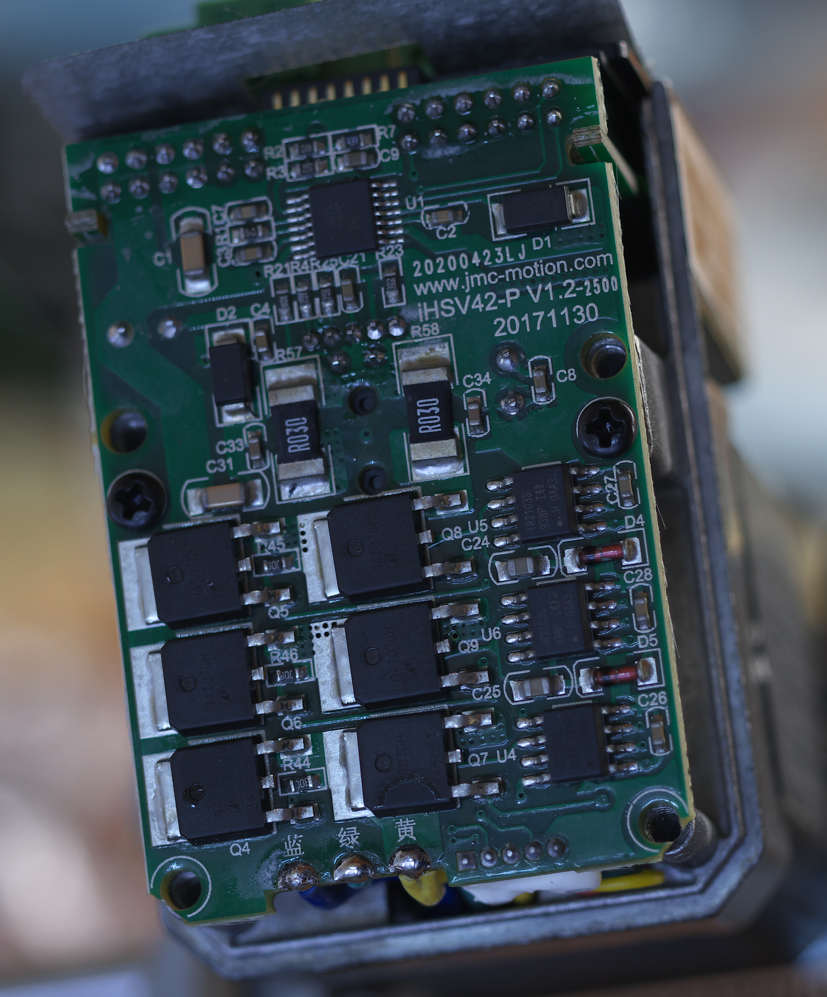
I opened one of the motors up to see what was inside. It turns out the encoder is optical.

Here's the PCB that sits over the end of the motor:
-
@fcwilt Thanks, but I am trying servomotors instead of steppers specifically because I want to understand servomotors better and see if there are any advantages in a 3D printer. One advantage has become apparent with the minimal testing I have done- they are absolutely silent.
-
@mrehorstdmd said in Testing servomotors in my printer... again.:
@fcwilt Thanks, but I am trying servomotors instead of steppers specifically because I want to understand servomotors better and see if there are any advantages in a 3D printer. One advantage has become apparent with the minimal testing I have done- they are absolutely silent.
Sorry about that. I wasn't clear. Since they make "premium" steppers with 5:1 ration planetary gearboxes I thought you might be able to find separate gear boxes with exact ratios as well.
Frederick
-
A couple of comments on this thread:
@fcwilt Are you sure the 'exact' 5:1 planetaries are really that? It's a hard number to get out of a planetary stage.
@mrehorstdmd The planetary drives that come with most steppers have rather large backlash, almost certainly worse than a belt system. The reason belts work so well in printers (2d and 3d0 is that they have been engineered to have miraculously low backlash. The planetary reduction drives work fine to give high torque in a single-direction driven systems. They also work well as extruder drives, since you are always pushing, and when you retract you get to remove the backlash when you un-retract. They are never really doing anything when running backwards.
-
@mrehorstdmd said in Testing servomotors in my printer... again.:
have less backlash than a simple belt reduction
I second @mendenmh 's good words about belt gears. That's the reason why I tried it also. The only problem is the compliancy when changing direction, where I found the proposed image. GT2 *) is optimized for low backlash. (T2.5, HTD etc. have higher backlash).
Thanks for opening the encoder, intesting.
*) unfortunately, GT2 is not standardized, better use the same manufacturer for pulleys and belts..., otherwise you'll get play again.
I've reread my post above, it can be misunderstood. I meant belt play of the compliance of the belt, i.e. it is difficult to get high tension, especially when using high torque. The teeth of GT2 have very low play.
-
@mendenmh said in Testing servomotors in my printer... again.:
A couple of comments on this thread:
@fcwilt Are you sure the 'exact' 5:1 planetaries are really that? It's a hard number to get out of a planetary stage.
I purchased one of each (economy and precision) to compare.
The steps/mm setting I ended up using seems to confirm the "economy" ones are are 5.18 to 1
The steps/mm setting I ended up using seems to confirm the "precision" ones are are 5 to 1
Frederick
-
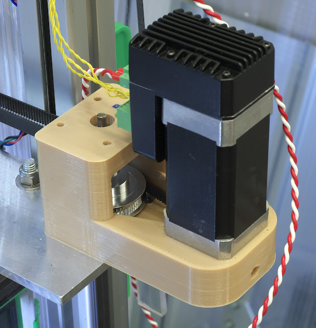
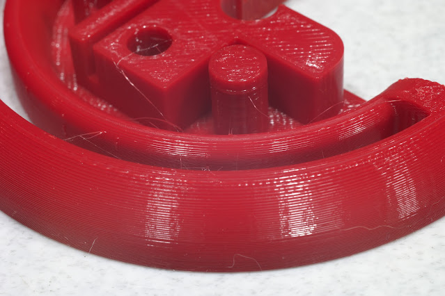
This is one of the motor mounts with 3:1 reduction. The motor has a 20 tooth pulley and the output shaft has 20 and 60 tooth pulleys. The output shaft is supported at top and bottom by F625 bearings. The mount is printed in two pieces without support. I used a pukey color PETG because I didn't know what else I'd ever use it for. The whole mount slides back on the aluminum plate to tension the corexy belt and the motor is mounted on slots to allow it to slide back to tension the loop belt. In the tests I've run so far the motors don't get more than a degree or two above ambient, even after an hour of operation. We'll see what happens with a much longer print.
-
@fcwilt OK, good to know you found both. The 5.18 is the much simpler (and cheaper) one. I have seen exact ones, like the 5.00, but they are more expensive. I think it requires a couple of stages to get 5 exactly, or a lot of teeth on the gears.
-
@mendenmh said in Testing servomotors in my printer... again.:
@fcwilt OK, good to know you found both. The 5.18 is the much simpler (and cheaper) one. I have seen exact ones, like the 5.00, but they are more expensive. I think it requires a couple of stages to get 5 exactly, or a lot of teeth on the gears.
My "MarkForged" style printer is using 3 of the 5:1 units on the belt driven Z axis. First time I used belts. I am a convert. Quiet and smooth.
Frederick
-
@joergs5 said in Testing servomotors in my printer... again.:
to set it to 2500.
Set what to 2500?
I looked up electronic gearing and it seems to be about getting multiple motors to sync to one encoder at the same or different speeds. With one motor and encoder, is there some value in using electronic gearing? How does electronic gearing relate to setting the steps per rev via dip switches?
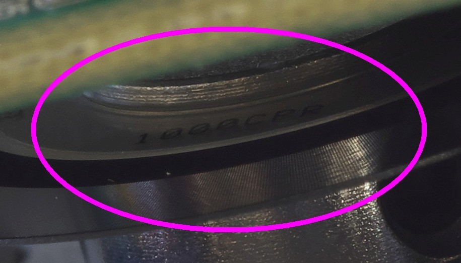
The thing has a 1000 line encoder so I would think that I should be able to set up 1000 steps/rev (assuming that the electronics has that high resolution)...
-
@mrehorstdmd said in Testing servomotors in my printer... again.:
Set what to 2500?
This seems to be an information from JMC's JASD drivers. There are models with 1000, 1250 and 2500 encoder lines. Please ignore. According to one forum user, JMC confirmed that the iHSV have 1000 encoder lines.
-
I've been doing a lot of digging into this and found a some useful things:
-
for the curious, here's a teardown with a bunch of photos of an iHSV57 (NEMA-23) servo.
-
I had a lot of problems getting JMC1.7.6 to work on my Windows 10 laptop. It kept throwing error messages about a log file already in use. I finally gave up and installed Robert Budde's python tool on the Lubuntu 20.04 netbook (2007 vintage!) that I use to send files to my printer. I installed the prerequisites per the instructions in the readme file without any trouble at all, and ran the program and it worked.
When you run it, there is a selection box that has you choose either iHSV57 v5x or v6x motors. The v5x selection didn't work with my iHSV42 motors, the v6x selection did.
- I found two English language videos that explain how to tune these motors using auto tune and manually tuning:
https://www.youtube.com/watch?v=_9Q-VFesnA0
https://www.youtube.com/watch?v=jvbw_PMOs-s
-
-
I wrote a gcode files that moves the extruder carriage back and forth at 100 mm/sec with 5k acceleration and used the tuning procedures shown in the videos linked above.
When I did the manual tuning (the second video) to minimize errors I didn't get any better reduction than I did with the first procedure using the autotune built into the drivers. So I went back to the first procedure using autotune and got errors down to +/- 2 steps with higher spikes at the points where the motors reverse direction (sort of expected that). The motors are set for 300 steps/mm, so +/-2 steps is <+/-7 um.
When I tried to print with the new tuning, curves looked good and didn't have the salmon skin or wood grain effect that was pretty bad with the factory settings, but I got a lot of layer shifts. I suspect the problem is that we use nonzero jerk in 3D printers because unlike a CNC mill, the tool doesn't meet any resistance other than the inertia of the mechanism. The jerk would also account for the much larger spikes in errors when the mechanism reverses direction. I suspect that 5k acceleration may be a little high, too.
This weekend I'll try tuning at lower jerk and acceleration and see if I can get it to print without shifting.
-
This is what a test print looks like using factory settings of the drivers and 3:1 drive reduction:

And this is what it looked like about 2 years ago, also factory settings, without the 3:1 drive reduction:

and this is what it looked like with 0.9 degree steppers:
-
@mrehorstdmd Hello,
I try now to wire up a JMC iHSV57 Servo to an RRF board, maybe you are so kind and help me to wire / set it right?this are the axis config line:
M569 P0 S0 R1 T4.0:5.0:6.0:11.0 ; physical drive 0 X goes backwardsThe board is sourced with 24V, the Servo with 30V.
Wired on the Servo to the board are
ENA+ > ENA
DIR+ > DIR
PUL+ > STP
ENA- > GND
DIR- > GND
PUL- > GNDGND of the servo input is also wired to the signal GND
The servo just flashes in one second interval infinite, the JMC 1.7.6 sw is working either but I have no clue which parameter needs to be set either in the servo or RRF to make it working.
Many thank's in advance for all your support!
-
@paulg4h I think your timing values look OK.
I used an expansion board for the Duet2 controller to get differential step/dir/enable signals. I believe that single ended 3.3V signals may not be enough for the input of the servomotor. I wired the expansion board Step+ to the step+ input, step- to step-, etc. and it works fine.
I think that if you're wiring it single-ended you may need a level shifter to get to 5V.Here's the manual for the motors . Page 40-42 covers the connections for step/dir/enable. It shows switched ground, high side switched, and differential input (which I used). There are couple links to youtube videos of the parameter tuning in English a couple posts up from this one.
Take a look at this to protect your power supply and anything else connected to it: https://drmrehorst.blogspot.com/2022/05/bank-account-protection-circuit-for.html
-
@mrehorstdmd manny thank's for your reply!
I will test that within the next days and come back to you!
-
@mrehorstdmd
After adding a level shifter from 3.3 to 5V the servo now works, even when there is no GND connection between the board and servo PSUJay point me to your reverse protection circuit, but I am based in Austria and need to build that at my own for only my four servos which would cost the same as four 36V 154W MeanWell PSU's which I use to drive them on my KillerBee.
-
@paulg4h You don't really need regulated supplies to power motors. If you use analog power supplies with plenty of capacitance you probably don't need to worry about power supplies blowing up due to transients.
The protection circuit protects anything that you might have sharing a power connection with the motor. If you don't share connections there's not much need for the protection circuit as far as I can tell.