optical ABL for 6HC OPB 880T51
-
@arnold_r_clark


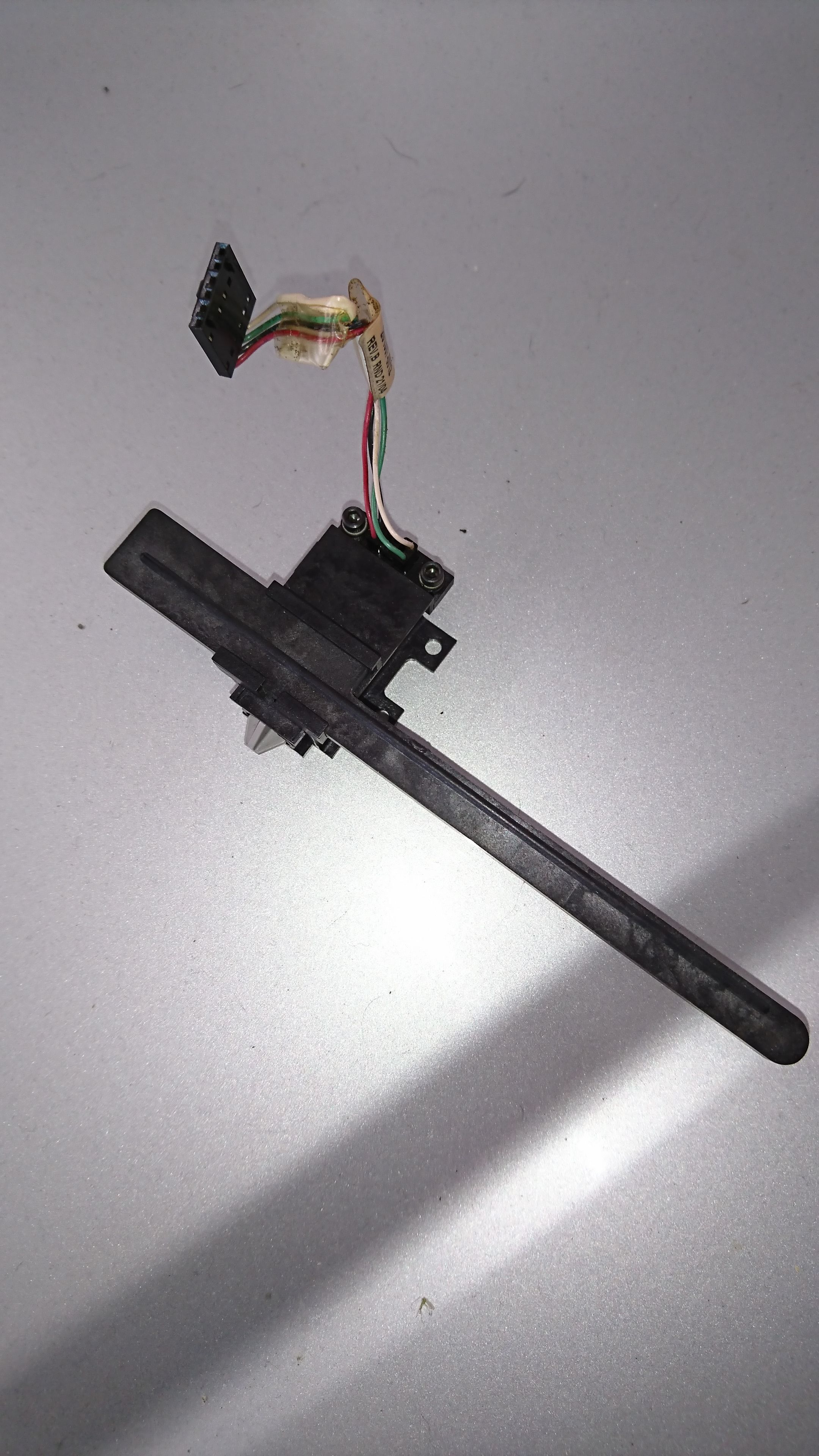
here is the abl i am using
the bar on this ABL is hit with tabs deploying the pin another tab is hit to return the probe
at the top you can see the pin to switch intersection is fixed an PCB OPTICAL will not fit this part unless i modifiy but not sure that is ideal the mounting is tiny tiny.... of course and would not fit unless i sepetate the pcb out board....hummmmthanks for your efforts
Cheers
-
@arnold_r_clark
i just re read your post to "correlation" missed that part my bad i understand to implement this and i am good....
question: does a 222 resistor and 101 come in an inline form how do you find the impedances to replicate or do you know what the values are for them OR do you think mounting this board remote is a better route
either way i get the set up now after looking at the 4 wires switch to 3 wire outs but I only thought there was one resistor needed so that 90%
thanks
-
@rexx use a meter dummy....
-
under your deployprobe.g lines 4 and 11 have : full colon yet 8 does not what does this difference mean?
if i set the reduce motor current for probing does it mean X30 y30 in the M906 means 30=300 mA each?
i have 3 nema 23 and 1 nema 17 so i think i will start at 800mA for the 17 and 1800 mA for the 23... for normal current how does the current reduction work by % or individual axis current set points?
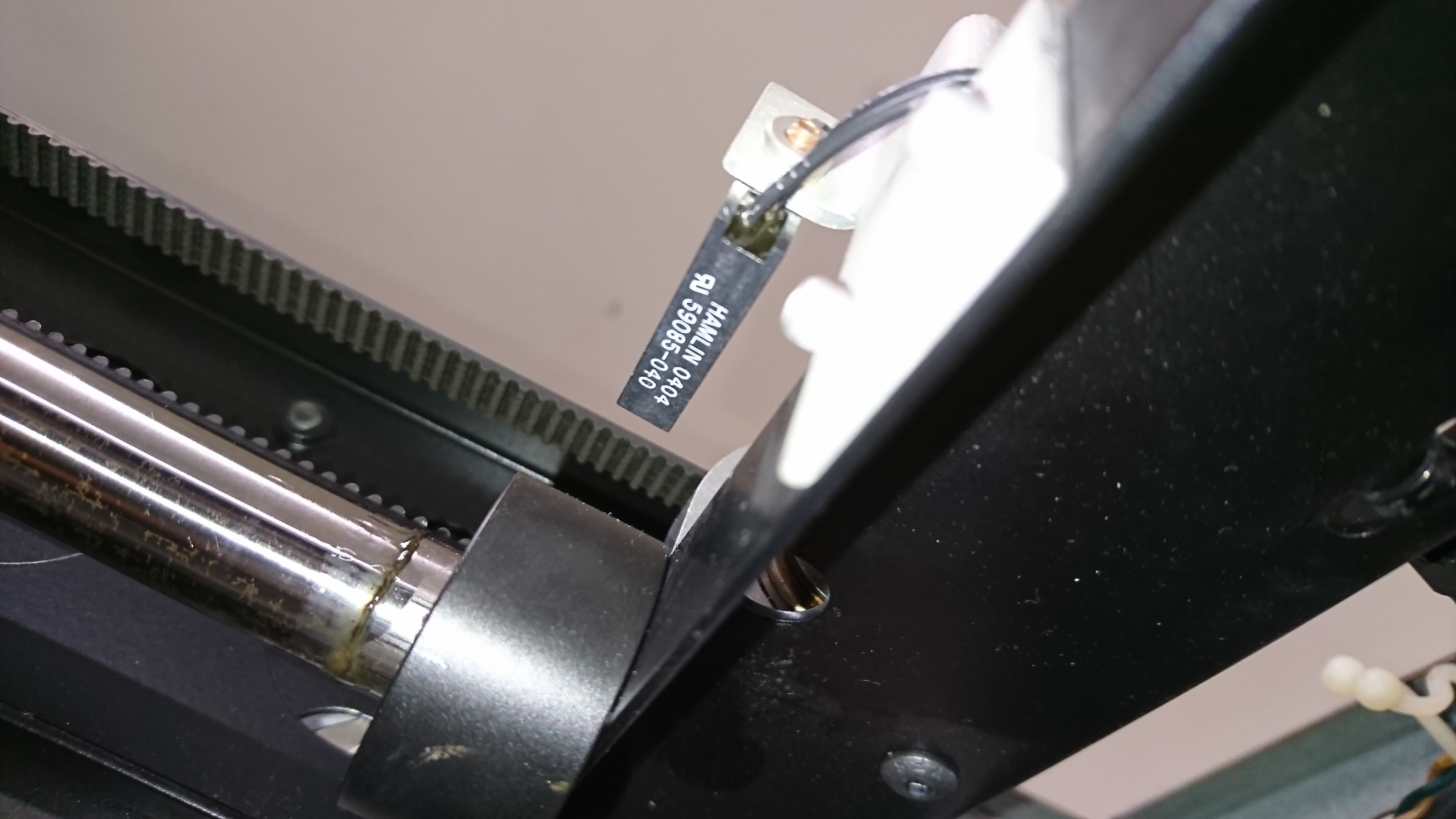
here is the 2 wire optical for xy stops they trigger with no power and a contact multi-metre setting just fine could i possibly use them like a micro switch? IO in and ground
they are hamlin 0404 (59085-040)
also noticed i think but can you momentarily go outside my X stop to deploy or do i need to move the stop so its with in the stops to deploy?
i am getting closer i can smell it and i haven't even plugged in yet
")
-
@rexx said in optical ABL for 6HC OPB 880T51:
under your deployprobe.g lines 4 and 11 have : full colon yet 8 does not what does this difference mean?
Lines 4 and 11 are M208 commands. I prefer the syntax variant where I set minima and maxima separated by a colon. Line 8 is a G0 command and the space in the example between Y and 220 is wrong. It should be
G0 Y220.if i set the reduce motor current for probing does it mean X30 y30 in the M906 means 30=300 mA each?
Good catch, that should have been M913. Sorry for this mistake! I will fix my mistakes now.
i have 3 nema 23 and 1 nema 17 so i think i will start at 800mA for the 17 and 1800 mA for the 23... for normal current how does the current reduction work by % or individual axis current set points?
With the M913 command as mentioned above.
-
so with M208 can i go outside the stops momentarily? like 10mm to deploy me ABL?
or must i have the abl inside the stops?
its a hit to deploy and stow and the stow is like 5-10mm past the stop but i could move the trigger tab to accommodate but don't want to if i dont need to.and can pass the stop slightlymy home pos is on the back right
my bed is 235x235x300
is it typical to use 0 for home or better to use closest bed corner from home as 0?reason is my home pos to the start of the bed is a bit like x30y180 if 0 is home
or am i better to use x-30y-180 for home
or should i just use ocotoprint and forget all this and baby step the numbers that way??and record...
i think my duet 2 is set home 0 bed +##
just trying to get an insight on the best approach here -
@oliof no applozies needed
-
@rexx it depends where the endstops are and if you can physically pass them by. also depends on the length of you trigger leg if you actually need to pass them by. Without more detailed photos of your printer I'll probably give misleading answers.
-
@oliof
good day,
the travel is there the oem setup allowed bump past the stop i have about an inch and only need .5" to tap the abl retract away but at the stop switch its not enough to complete the retract probe tap completely the printer was duel material and nozzzles and now only one so i have extra roomit also may make more simplicity to simply chop the trigger tab down .5" where any home would retract the probe if it was deployed when homing then i only need deploy.g i think...
and i would need to home in a way it goes to the back center (outside the bed) then x's homed as the tabs and slider are to be hit from the side to side not back to frontfor deploy similar just the other sides tab but first must be somewhere in the middle of x then to the back not to catch on an angle but side to side for the ABL use only.
when just the x stop is hit can it go 13mm more in that direction being told in the code for only x stop?
-
i will snap a pic soon for you getting close with the wiring
for my abl optical switch if i use a 10k resistor across 5v and gnd guys said series resistor is that diffrent or just the way its wired?
are they directional a typical resistor?
sorry for all the school questions...
the head is back in the machine and its not gonna ever print single wall print with only supports at 2000% (the oem limitations no wall line counts 1 only no turning off supports N/A no raft N/A to revome either the sparse or 100% infil option only is pure sponcership)
now just dont crash it... stay tuned -
@rexx said in optical ABL for 6HC OPB 880T51:
hamlin 0404 (59085-040)
hey good day
the two wire hamlin switchs are magnetic so A.picture is how they will go correct?
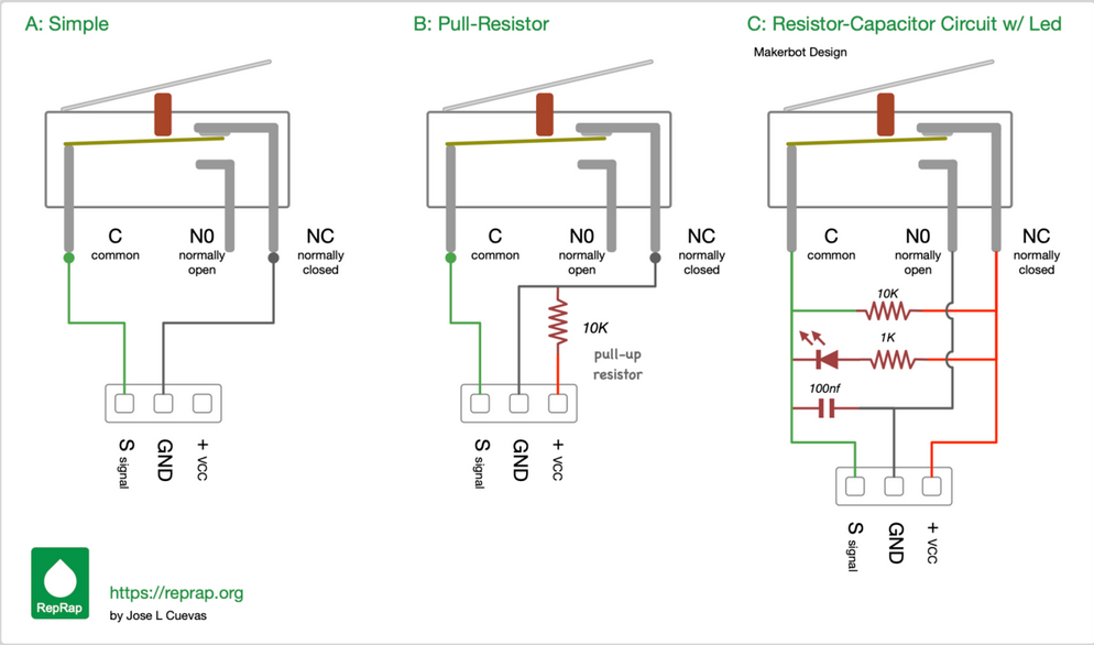
does my opto 4 wire need to be wired like B pic or C picture for use as probe trigger
-
@rexx The schematic in picture "B: is incorrect.
The pullup resistor should be between "+VCC" and "S signal" like it is in picture "C".
I don't understand your question about B vs. C so I can't help with that.
-
Optical switch :as for the resistor i have 180 ohm 2W resistors 330 ohm 1W resistors 10K 1/2W
i think i should use 5V side with 330 ohm /1w would this be fine?
do i need 2 or just one i have found two diffrent ways the PCB shows 2... -
@rexx said in optical ABL for 6HC OPB 880T51:
question: does a 222 resistor and 101 come in an inline form how do you find the impedances to replicate or do you know what the values are for them OR do you think mounting this board remote is a better route
Yes, 222 is a 2.2Kohm resistor and 101 is a 100 ohm resistor - except that it looks to me that the marking is actually 181 which makes it a 180 ohm resistor.
The 180 ohm resistor sets the current of the IR LED in the opto switch. The 2K2 resistor is a pullup resistor on the output. Its value is less critical, so your 10K resistor should work OK instead.