Pressure advance and variable flow ratio
-
TLDR; I think the speed matching algorithm in the motion planner should favor matching the extruding velocity if applicable, instead of the combined speed, to prevent over/under-extrusion on flow ratio change.
Dear RRF developers,
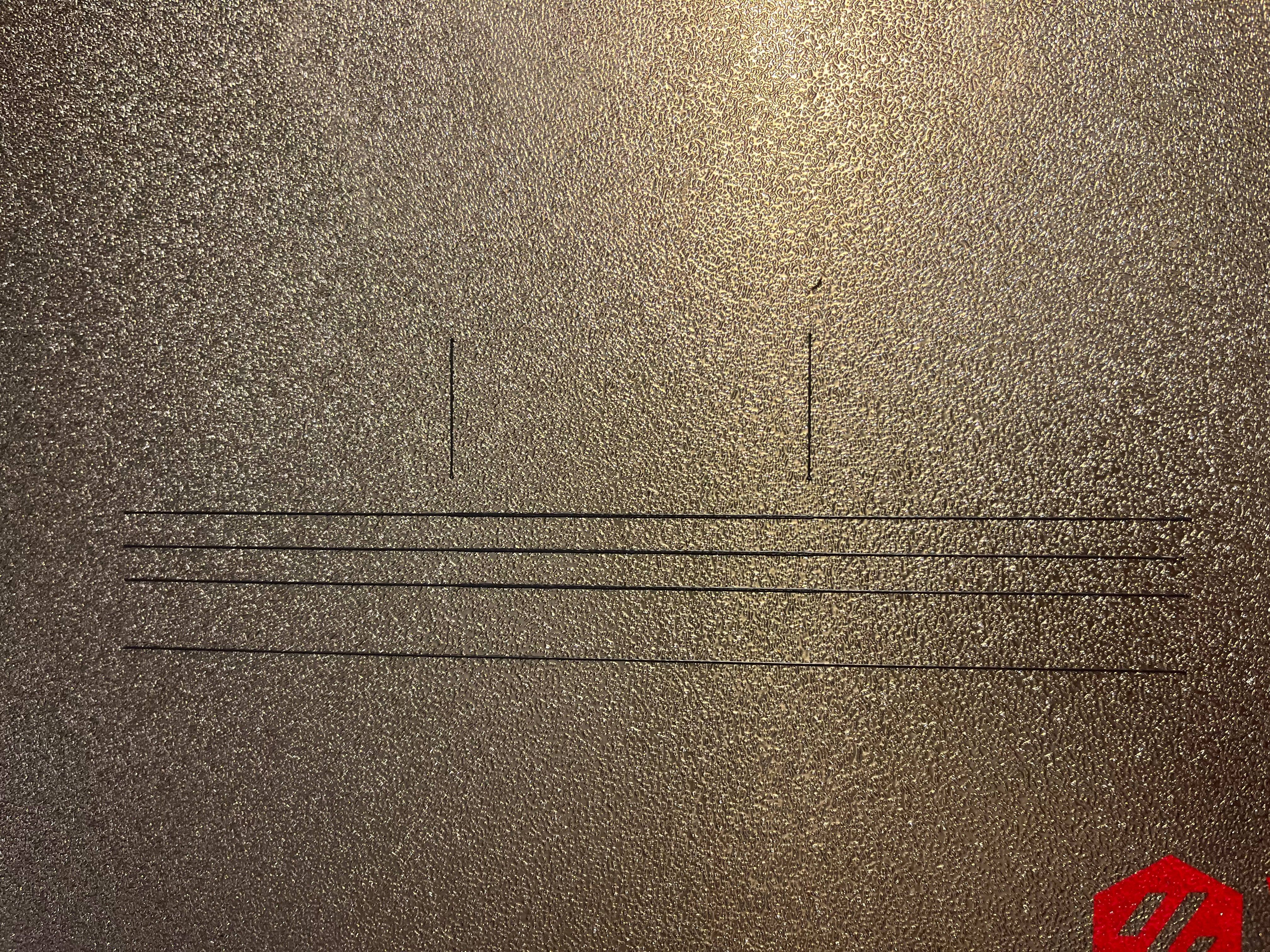
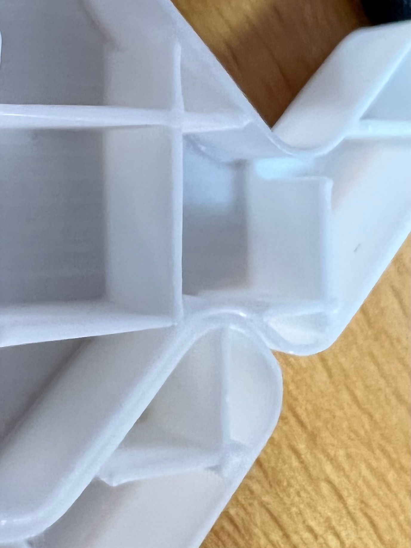
Recently I've been investigating bridging quality issues on my RRF Voron printer. The symptom is that the beginning or bridges are always heavily under-extruded to the point that half of the time it collapses for being too thin. I made a simple bridge STL trying to troubleshoot the issue:
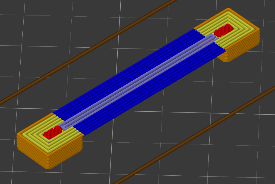
This is designed to test the scenario where a perimeter enters bridge without turning. I tried to adjust target printing speed so that it maintains a constant volumetric flow rate, but the problem persists. The only way I could get acceptable bridges is to reduce bridge speed to very low value (< 15mm/s).I believe the problem is due to the speed matching algorithm trying to match combined speed instead of extruding velocity, this caused instantaneous extruding velocity change that is impossible to compensate by pressure advance.
void DDA::MatchSpeeds() noexcept
{
        for (size_t drive = 0; drive < MaxAxesPlusExtruders; ++drive)
        {
                if (directionVector[drive] != 0.0 || next->directionVector[drive] != 0.0)
                {
                        const float totalFraction = fabsf(directionVector[drive] - next->directionVector[drive]);
                        const float jerk = totalFraction * beforePrepare.targetNextSpeed;
                        const float allowedJerk = reprap.GetPlatform().GetInstantDv(drive);
                        if (jerk > allowedJerk)
                        {
                                beforePrepare.targetNextSpeed = allowedJerk/totalFraction;
                        }
                }
        }
}
For example, let's say we have target perimeter speed of 60mm/s. Assuming 0.41mm extrusion width and 0.20mm layer height, the target flow rate would be 4.92mm^3/s. To maintain a constant volumetric rate, the bridge speed needs to be 39mm/s. Example:
M83
G0 X0
G1 X10 E3.409 F3600
G1 X20 E5.224 F2349
However, IIUC, constant flow rate is not going to happen with the current motion planner implementation, even if XY jerk limits permit it. The behavior is to pick the slower of the two as the target transition speed, then verify if the direction change is permitted by jerk limits. In this case, the transition speed would be F2349, thus causing a mismatch in extrusion velocity, which can't be compensated by pressure advance because it requires instantaneous position change.
This can be mitigated by setting an artificially low E jerk value, so that
MatchSpeedsreturns a low transition speed. However that is not ideal because it basically causes such transition to always grind to a halt, and also limit acceleration to an extreme low value due to this inDDA::InitStandardMove:if (flags.xyMoving && nextMove.usePressureAdvance) { const float compensationTime = reprap.GetPlatform().GetPressureAdvance(LogicalDriveToExtruder(drive)); if (compensationTime > 0.0) { // Compensation causes instant velocity changes equal to acceleration * k, so we may need to limit the acceleration accelerations[drive] = min<float>(accelerations[drive], reprap.GetPlatform().GetInstantDv(drive)/compensationTime); } }I think this double usage of E jerk is a mistake. It makes no sense because not only it's being applied twice, but also it is applied in different spaces. In
DDA::MatchSpeeds()it is being applied to pre-pressure-advanced velocity, while inDDA::InitStandardMoveis being applied to pre-pressure-advanced acceleration, i.e. post-pressure-advanced velocity.IMO the two usage of the E jerk values really should have used separate variable. Or for the sake of simplicity, I propose that the allowed E jerk during
DDA::MatchSpeedsreally should have been 0, and we should allow the combined speed between the current move and the next move to mismatch, as long as jerk limit permits. In fact the behavior will be identical to current implementation when flow ratio remains constant, because matching extrusion velocity implies matching combined speed when flow ratio is constant. -
Here's a benchmark I made to demonstrate the issue. The test prints 4 lines:
#4 A line with 0.41mm --> 0.72mm --> 0.41mm transition, same target speed, with pause in between
#3 A line with 0.41mm --> 0.72mm --> 0.41mm transition, variable target speed, constant target flow rate
#2 A line with 0.41mm --> 0.72mm --> 0.41mm transition, constant target speed
#1 A constant width line with variable speed. To demonstrate the pressure advance value being appropriate.
(Printed from bottom to top.)
In theory if pressure advance is working properly line 2, 3, 4 should be printed identically. But in the actual result the top line #4 has the sharpest transition. Line #3 and #2 has transition delayed towards the right and averaged out.
My apologies that I only have a coarse textured build plate. It should be more obvious when printed on a flat plate. Here's the gcode for you to reproduce the issue.
E_jerk_test.gcodeG21 ; Millimeter units G90 ; Absolute XYZ M83 ; Relative E T0 ; Switch to tool 0 M190 S105 ; Set bed temperature (wait) M109 S250 ; Set nozzle temperature (no wait) M204 S1000 P1000 ; Acceleration M572 D0 S0.05 ; Pressure advance ; Purge line G1 X50 Y50 Z0.2 F18000 ; move to start G1 X50 Y100 E2.754 F3600 G1 X50.72 Y100 E0.040 G1 X50.72 Y50 E2.754 G1 E-0.2 F2400 ; Retract ; Line 1: Same line width, different speed G1 X75 Y50 F18000 G1 E0.2 F2400 ; Unretract G1 X125 E1.568 F1200 G1 X175 E1.568 F3600 G1 X225 E1.568 F1200 G1 E-0.2 F2400 ; Retract ; Line 2: Different line width, same speed G1 X75 Y60 F18000 G1 E0.2 F2400 ; Unretract G1 X125 E1.568 F3600 G1 X175 E2.753 F3600 G1 X225 E1.568 F3600 G1 E-0.2 F2400 ; Retract ; Line 3: Different line width, maintain volumetric rate G1 X75 Y65 F18000 G1 E0.2 F2400 ; Unretract G1 X125 E1.568 F3600 G1 X175 E2.753 F2050 G1 X225 E1.568 F3600 G1 E-0.2 F2400 ; Retract ; Line 4: Different line width, same speed, with pause G1 X75 Y70 F18000 G1 E0.2 F2400 ; Unretract G1 X125 E1.568 F3600 G4 P1 G1 X175 E2.753 F3600 G4 P1 G1 X225 E1.568 F3600 G1 E-0.2 F2400 ; Retract ; Indicator lines G1 X125 Y75 F18000 G1 E0.2 F2400 ; Unretract G1 Y95 E0.627 F3600 G1 E-0.2 F2400 ; Retract G1 X175 Y75 F18000 G1 E0.2 F2400 ; Unretract G1 Y95 E0.627 F3600 G1 E-0.2 F2400 ; Retract ; Lift Z G1 Z10 F300 -
I don't know if "Firmware Wishlist" is the right place for this as this looks to me like a unwanted behaviour of pressure advance.
Printer: Voron 2.4
Extruder: LGX (not lite)
Board: Duet 3 Mini 5+
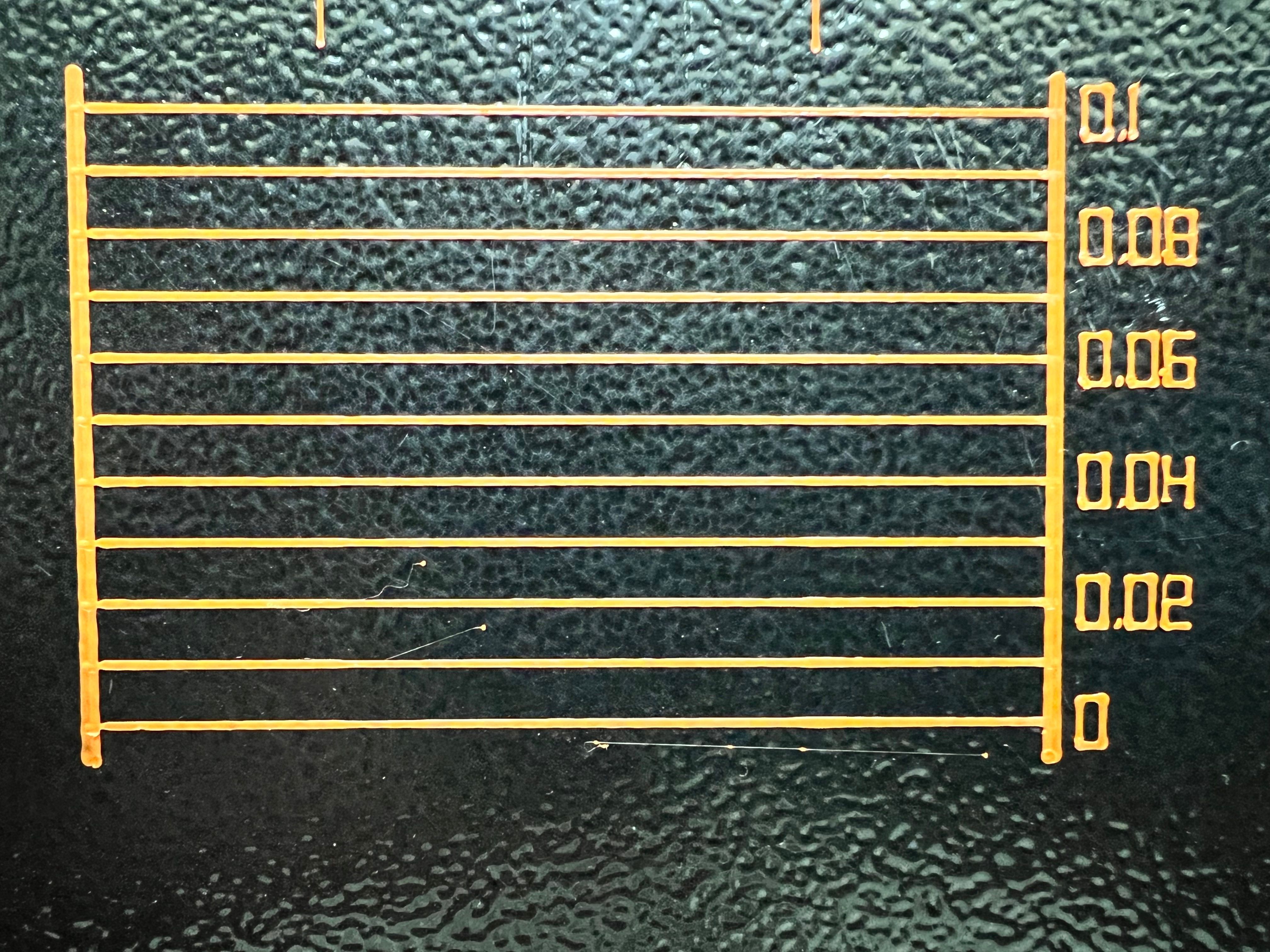
FW: 3.4.1- Pressure Advance PLA test pattern with high speeds (60mm/s to 160 mm/s at 4.000mm/S acceleration):

Result are looking good at PA 0.06.
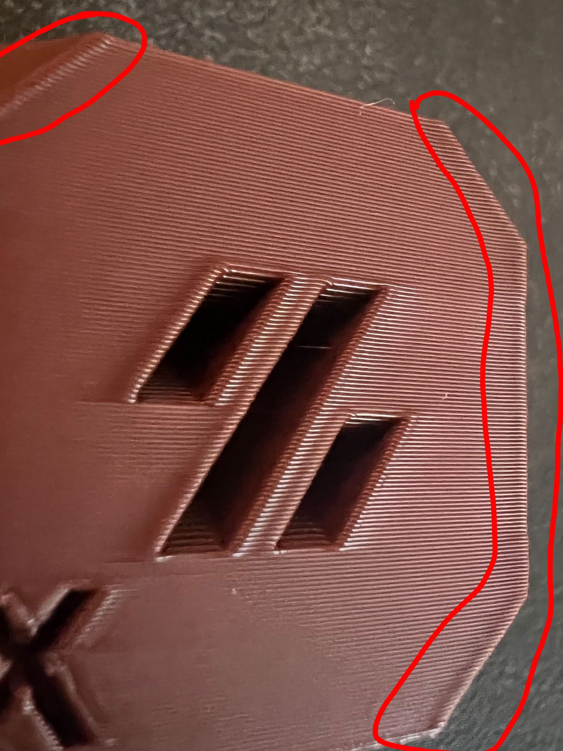
- But the print then looks like this with bulging corners (external perimeter speed at 80 mm/s, 1.200 mm/s acceleration):

- To get rid of the bulging corners I further increased PA (0.1) to the extend that infill lines don't connect anymore with perimeter:
Heavily increase infill overlap to 200% or so would "solve“ this but that causes other artefacts / issues. So that is not really a solution imo.
I saw this behaviour since the RRF 3.4 beta6(?). With RRF 3.3 corners were sharp(er). I'm using input shapers and I know that PA has to be retuned, hence the test pattern above.@dc42 Maybe you could please take a look at this? Normally I would not ping you but I recon RRF isn't the community were people always directly update to the newest version (RRF 3.4) when the printer is running fine. Thanks!
-
@Argo - quick question (followed by no additional insight, I'm just trying to understand more on this topic since I'm trying to tune PA and IS on my machine). My question is the units on you acceleration on pictures 1 and 2 - your units are mm/S, and the value is 1.2 or 4. The value seems extremely low if the acceleration units are actually mm/sec^2. Or is this acceleration really a jerk value (mm/s per Step?)
-
@mikeabuilder I think he mean 1200mm^2/s and 4000mm^2/s. The dot is the digit delimiter, not decimal point.
-
@trchen - well, that makes a lot of sense.
-
I think Firmware wishlist is probably not the right place for this post. It is not really a new feature, but more of tweaking.
My apologies for tagging you directly, @dc42, just want to make sure you are aware of it. We have a few users at Voron Discord who suffered from PA-related issues that is specific to RRF.
I did some more experiment afterwards. I wrote a SuperSlicer postprocessing script to insert a short pause
G4 P1(basically forcing RRF to decelerate to 0) when flow ratio changed by more than 5%. It mitigated my bridging problems even if printing at normal bridging speed (75mm/s). It is only circumstantial evidence but I think it's worth some investigation.Here's my SS script if anyone's curious:
#!/usr/bin/python3 import sys from io import StringIO from math import hypot THRESHOLD = 1.05 x = y = None e_rate = 0.0 buffer = StringIO() for line in open(sys.argv[1], "r"): if not line.startswith("G1 "): buffer.write(line) continue dx = dy = de = 0.0 for clause in line.split(): if clause[0] == "X": if x is None: dx = None else: dx = float(clause[1:]) - x x = float(clause[1:]) elif clause[0] == "Y": if y is None: dy = None else: dy = float(clause[1:]) - y y = float(clause[1:]) elif clause[0] == "E": de = float(clause[1:]) if dx is None or dy is None: buffer.write(line) continue dxy = hypot(dx, dy) if dxy < 0.00001: new_e_rate = 0.0 else: new_e_rate = de / dxy if e_rate == 0.0 or new_e_rate == 0.0: pass else: ratio = new_e_rate / e_rate if ratio >= THRESHOLD: buffer.write("G4 P1\n") buffer.write(line) e_rate = new_e_rate with open(sys.argv[1], "w") as f: f.write(buffer.getvalue()) -
@droftarts could you please move this thread to a more suitable category? Hopefully someone will then take a look at this. Thanks!
-
@argo it needs @dc42 to look at it. I’ll highlight the thread to him on our internal comms. We don’t really have a ‘firmware issues’ category, so here is fine.
Ian
Bed-slinger - Mini5+ WiFi/1LC | RRP Fisher v1 - D2 WiFi | Polargraph - D2 WiFi | TronXY X5S - 6HC/Roto | CNC router - 6HC | Tractus3D T1250 - D2 Eth
-
@trchen thanks for sharing your thoughts. Have you tried building a version of the firmware with permitted extruder jerk set to zero in DDA::MatchSpeeds? If you haven't, would you like me to build one for you?
-
@argo just a side note that I am not surprised RRF3.4 with IS does cause rounded corners because that's what IS effectively is for -- smoothing out the movement so it's not a sharp direction change that induces ringing. If you disable IS in 3.4, do you regain the sharp corners?
-
Input Shaping only has marginal effect on how the corners do look like. I did tests with and without IS.
I did also play around with different jerk settings (5 mm/s up to 15 mm/s) and the result is also pretty much the same.For testing purposes I would like to revert back to RRF 3.3
but it seems the 1LC rev 1.1 is not supported by RRF 3.3 because I can't activate the heater.As far as I remember I did not have this issue with RRF 3.3 but that can still be a coincidence.Edit: I'm not sure the issue I'm having is related to the findings of trchen and I don't want to hijack his thread, so I'm creating a new one with my findings.
-
@dc42 I haven't, but I'm happy to try! I predict it will have similar effect as my slicer postprocessing script. I'll do an experiment to see if it reinforces or disproves our theory.
-
I just got my build environment set up. I will be busy at work this week, probably will start my experiments over the weekend.
The first experiment would be hardcoding the E jerk during MatchSpeeds to some small value and see how bridges behaves.
(The jerk value can't be zero due to FP errors. Something like 0.01 is probably more reasonable. I feel MinimumJerk==0.1 may still be high for extruders.)I still haven't think through what a better jerk policy should be. Allowing the total speed to mismatch between two moves doesn't feel right either because multiple rapid small moves could rack up a lot of speed change in small amount of time.
On the other hand, what's so different with the policy we have today? With the current jerk policy you can make a lot of small moves to form very small turn radius, effectively bypassing the acceleration limit. For example, Gyroid infills are notoriously demanding for acceleration. I suspect we are actually able to cheat by breaking down curves to multiple small moves, by setting "Slicing --> Filtering --> Internal resolution" smaller in the slicer.
An idea I have in mind is to maintain a "jerk potential" which is recharged at the rate of acceleration while capped at the jerk maximum. Once the jerk potential is depleted no more instantaneous speed change is allowed.
-
undefined Argo referenced this topic 29 Oct 2022, 19:14