New heated enclosure printer
-
@phaedrux Yes, I babysit the first couple of layers so it is not a problem. First I sliced with 90% initial layer flow, it still happened, so I ended up down at 82% with the DWC slider. That's pretty far off! I guess it is time to look at the actual bed height at Z0 again. I did the standard procedure of setting it at zero with a sheet of paper under the nozzle when hot.
The first layer surface quality was a lot better. But there was still a little blobbing at the ends. Maybe a little less of infill overlap percentage.
-
Getting some really nice big prints out of the machine and even though I know there is still more slicer tuning to be done I just need the parts too much to slow down and do some careful tuning. Oh well, the many prices of success!
I now have the Cura 4.13 settings to 90% flow everywhere and 82% on the first layer and no filament tending is needed, at least for these two recent prints. On the first layer the brim top surface finish is quite nice, but the infill still is a little squishy at the ends where it merges into the perimeters. I'm not sure, but it seems to be overprinting some areas. I only notice it while tending the printer at the start of the cycle because these areas are covered by printing.

Tha areas that are least acceptable are mostly the bottom surfaces that are above supports and the bottom edges of some transitions that do not require supports.

I know that with a larger nozzle, big layer size, and fast print speeds there are limits to what can be achieved, but I am not sure how close to those limits these results currently are.
-
@coseng said in New heated enclosure printer:
@dc42 OK, that is some info. How would I do that? Another option is to rig up an independent arduino logger. I guess if it is printing fine then no reason to fix it!
The average PWM of each heater is in the object model, in heat.heaters[N].avgPwm.
Duet WiFi hardware designer and firmware engineer
Please do not ask me for Duet support via PM or email, use the forum
http://www.escher3d.com, https://miscsolutions.wordpress.com -
@dc42 OK, thanks. Sorry for the novice question, but would I enter that in the DWC command line? If I put it at regular intervals in the gcode would the machine console echo them for a DIY logger?
-
@coseng to get the PWM for heater 1 echoed to console as a JSON reply, use this:
M409 K"heat.heaters[1].avgPwm"or use this to get it as plain text
echo "Heater 1 average PWM is", heat.heaters[1].avgPwmDuet WiFi hardware designer and firmware engineer
Please do not ask me for Duet support via PM or email, use the forum
http://www.escher3d.com, https://miscsolutions.wordpress.com -
@dc42 Thanks!
-
Still happily printing away and chipping away at the minor underside blemishes but overall very happy with the overall print quality and speed.
Not leaving well enough along I tried to print the windscreen in clear PC. The print came out geometrically fine and is somewhat translucent.
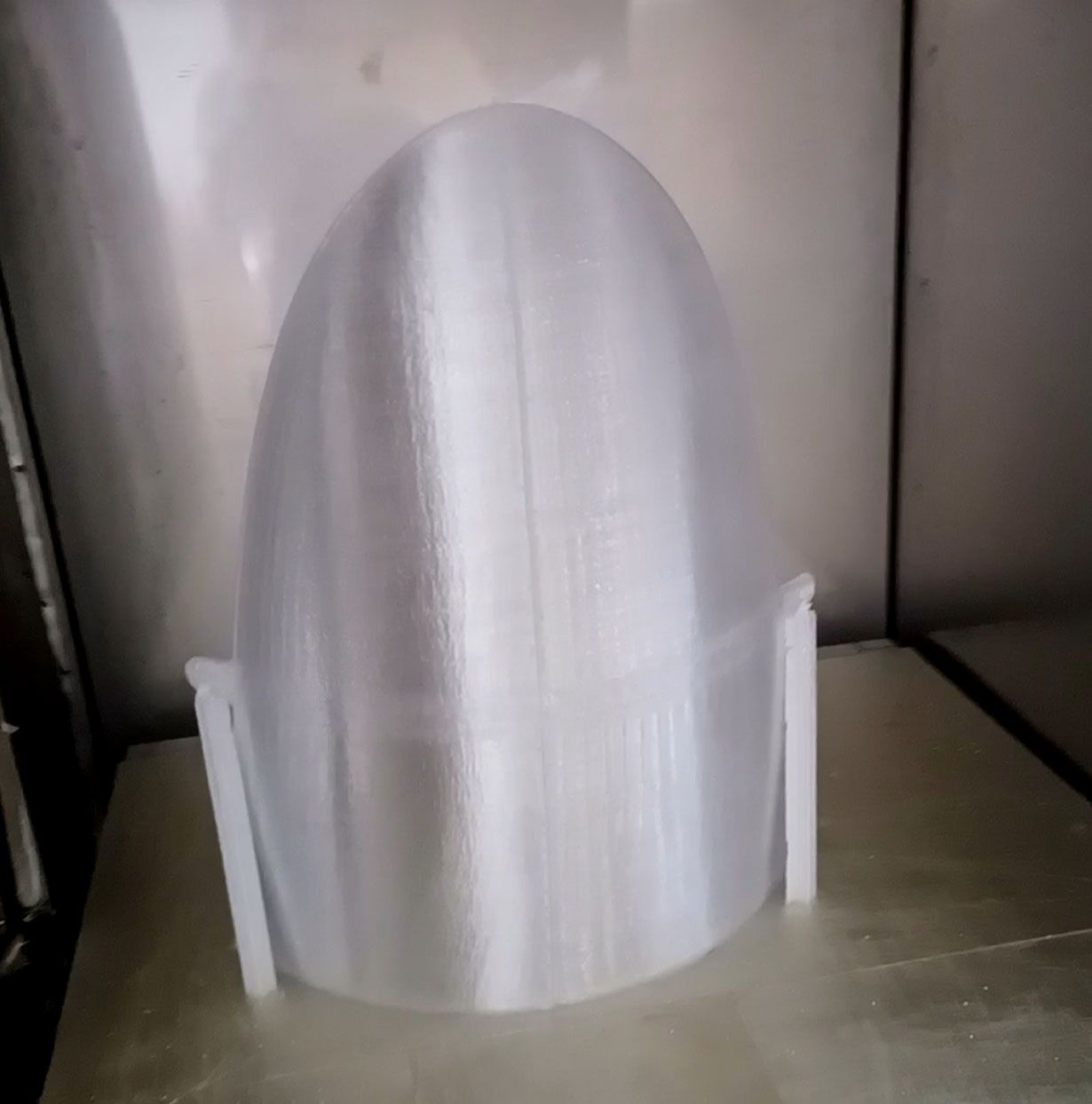
I'm not sure what I was hoping for in the optical quality department, but somewhat better than I got. I wonder if some wet sanding would improve things.

The print settings were 260C printhead/110C bed/60C chamber with the layer fan starting at 0 and increasing 20% every hundred layers after layer 200. The PC is noticeably stiffer than ABS.
Thinking ahead a bit to some last tweaks, I am going to use Cura to do some g-code post processing to limit the accelerations and maximum speeds as Z increases past 250mm or so. Those parts are standing on edge and I can see some wobbling when the printhead does its rapid moves.
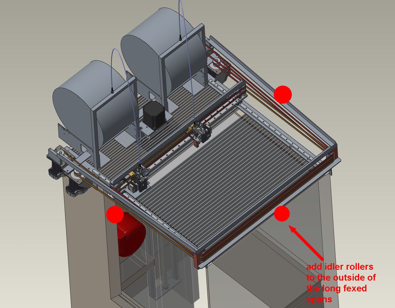
I may also add a couple of outer belt rollers the long spans as I can see the belt vibrating a bit when the printhead is doing short reversing infill travels at high speed. There is no audible or visible artifacts from it, but mechanically it would not be bad to eliminate.
-
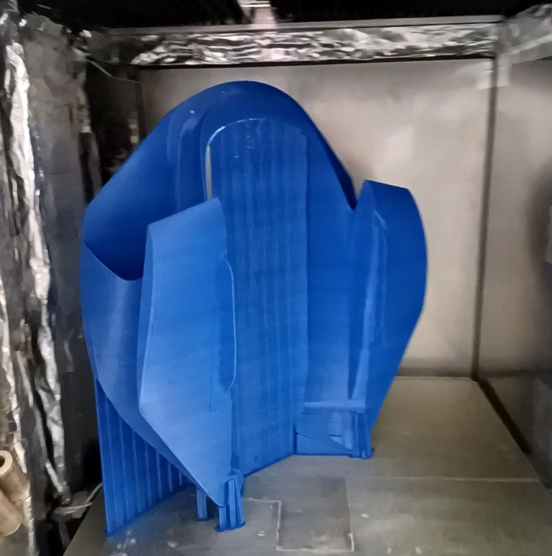
OK, first big print failure. this was a sizeable part, 510x580x820mm that would have been about 5kg. I stopped at about 600z.

I paused it after about 300mm and was noticing some of the part sections swaying back and forth and tried to tape them to the more stable tree support sections, and that helped somewhat, but was not enough in the end. I need to add some more support in CAD that is attached to the part and will be cut off. It seems crucial where there are segments of the part that start on different islands on the bed then merge at some higher Z point. If there is any misalignment around the merge layers, the printhead hits one and knocks it out of place and then a cascading failure starts.
Before pausing to add the reinforcing tape I did notice the print nozzle hitting some of the part and tree support areas as it rapided over them. This makes me think that I do not have the feed amounts properly calibrated and am stacking a bit high on Z and causing the printhead to hit and knock it out of place. I can also add Z hopping but would like to get the physical characterization of the extrusion correct first instead of just adding band aids on top.
-
Round 2 was a success!
Or mostly a success. Definitely a usable part for initial track testing but the print does have some blemish areas.
I added Z hopping at 1mm so there was a ton of z motion going on but it did not affect the print time that much. The Z motor was a lot hotter. I may have to tune the retraction settings now as at some points it seemed to be depositing a tiny drop of material, z hopping to a couple mm away, and repeating for 30-50 times in a row. I am not getting any blobbing or stringing issues, so likely have some margin to reduce retractions.
The added z motion did accentuate the instability of really tall (500mm+) and slender support structures, as you could see them swaying back and forth a bit. Once the printhead was printing on them the motion was quickly damped, but it has a noticeable effect on surface print quality. I think the fast accelerations of the printer are causing problems when the center of mass of the printed plastic for an island is not over its center of support, so when I create these new CAD supports will try to either prevent that situation or try to give the added bracing some torsional stability. I found that adding 1 perimeter wall option to the support generation adds a lot of stability to the support islands, but it also greatly increases print time and support removal difficulty.

I think most browsers should play this video: https://www.instagram.com/p/CfKd1oqDCpV/
The part ran with a bunch of Cura generated supports around a bunch of 3 pass wide brace walls that were added to the CAD model in Creo. The uppermost horizontal walls were a bit wonky as a result of my added walls ending too soon and the Cura supports wobbling a bit. This wonkiness stopped when these islands were merged into the overall part perimeter, which was pretty stable due to the CAD added bracing.

So these parts are all good enough for initial assembly, dyno and track testing, but there will definitely be a round 2 once that all happens. When I do this part again (and actually for some other parts too), the supports will be revised to something like this:
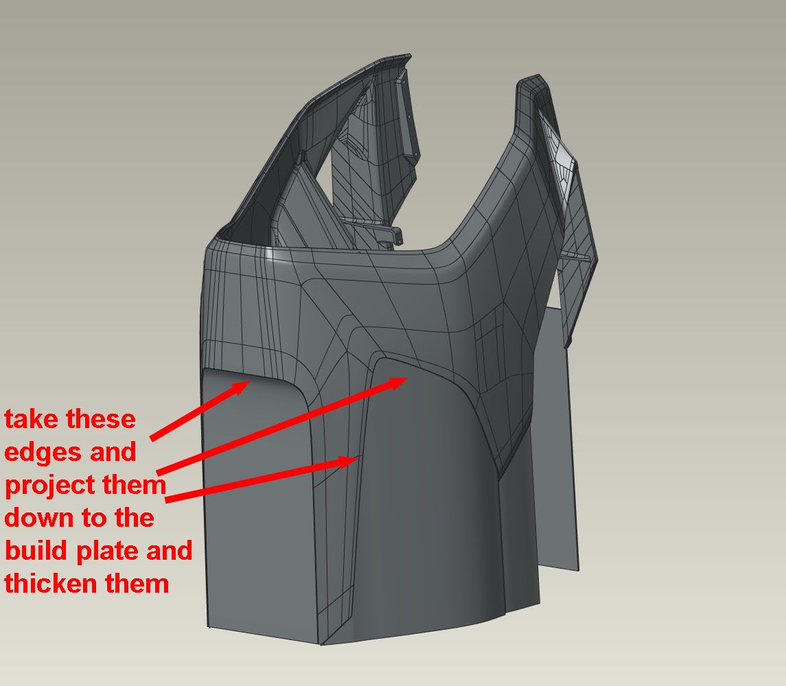
Basically, after orienting the part I will take the edges that are above the build plate, drape them down to intersect the build plate, then thicken them to 3 print passes. This will eliminate any isolated islands on the print bed and it will also convert the part from long, spindly and unstable fingers and supports to a stable closed profile with few supports. The rest of the fairing is about 5mm thick, and done with 2 walls and 10% gyroid infill. The result is that the added walls are 'solid' where they merge into the part so can be trimmed off without breaking through to the infill. The added part volume seems to be a decent amount less than the support structure it is replacing, and because they are usually long smooth print moves can be done at a consistent realized 150mm/sec, so also print decently faster than constantly reversing support movement.
I found that cutting these style ribs off was pretty easy with an oscillating handheld cutters (dremel mm35). No melting and with the right blade shape (standard one included in package) it was easy to get near flush cuts. No nicked fingers, either!
This last print was 52hrs. The printer has been going almost continually since 5/16 with no more than a few hours between prints. I've gone through about 28kg of filament so far. The only failure was the filament stepper fan, which burned out. Turns out it was a 12V fan running at 24V. I may add some shielding between the chamber heater elements and the build plate, as on the previous failed print it did seem that the heater on one side caused some of the single wall tree supports that were directly opposite it to sag. Other than that, the printer has been mechanically sound, which is great.
-
Hey nice job on your build and cool parts made from it
do you plan on trying any HT Resins/filaments? IC you tried PC whos PC was it or at what temp did you print it 280C-310C? Real PC like LEXAN PC is owned by Sabic innovations invented by GE in the 70's and most others are a PC blend usually below 270C and is not like Virgin PC HF1110 or even comparable in my opinion but am curious what that PC was...
-
@rexx Thanks! The material for the PC part was ordered from pushplastic.com and is listed as 'polycarbonate' . I don't know the material details, but it felt a lot stiffer than the ABS filament. It printed at 260C, but my temp settings seem to be a bit lower than most other printers. With the thorough printhead insulation and copper print nozzle I likely get a higher heat transfer rate so need a lower temp to get the same energy to the filament.
I don't see trying any higher temp materials unless forced to by melting ABS parts. The end goal is motorcycles, and it is easy to get lost in printing experiments.
-
@coseng you may want to use ASA at least your uv stability will stand the test of time alot of ABS will fade split sag from the UV rays you have a much better chance long term UV exposure with ASA they run very close to the same with the avg density of around 1.07 and abs 1.05-1.12 SG and is the same price
-
ASA is better than ABS in every way, except cost.
-
For production motorcycles these parts are injection molded in ABS, so figure matching that is the path of least resistance.
Chris
Cosentino Engineering -
@phaedrux from a resin stand point Sabic vs sabic ASA is $2.28/KG cdn 1600 lbs gayloads min loads ABS MG 94 is 2.12/KG or 96cent/lbs so a delta of like .05$ a lbs from asa to abs is not really diffrent your talking the brand influances asa can be had as cheap as abs and vise versa but makers like to inflate the underdogs due to tru put like 3dxtech asa is way overpriced at 60$/roll vs others at 25$/roll my point is asa or abs is not a real diffrence in price but the end seller or brand maybe apples to apples they are only 0.05$/Lbs away from each other at a resin stand point the rest is nike shoes! its sabics resin not 3dxtech or VM but SABIC they set the pricing the rest is inflated less L and O labor and overhead!
but both are very similar in cost -
@coseng
it would be the path of least resistance yes would you build one specific or source the run out? -
@rexx said in New heated enclosure printer:
it would be the path of least resistance yes would you build one specific or source the run out?
Not sure what you mean.
Truckload pricing in pellet form is not really relevant to a small quantity user like myself. ABS filament seems more generally available than ASA. Pushplastic.com has 10kg spools in many colors in stock. The 10kg spool size really helps with these big parts.
If I have temp issues with parts near the exhaust melting, I can give the ASA a try. Otherwise if it ain't broke, I don't have time to fix it!
")
-
@coseng i was just saying to the comment before asa vs abs cost $$ is not relavent good abs and good asa is priced very similar and it is what it is. as for the 10 kg spools if you want to run will be hard to beat normally the larger rolls are only found 4-5 lbs or 2-2.2KG
-
Win a few, lose a few.
I tried running a thinnish part standing up with minimal slicer supports but thought decent CAD bracing and got an area with a failure similar to the initial thin part print failures where the end got all wiggly.

I also had an issue with the one of the chamber heaters blowing on the part and causing some sagging and warping. I tried to heat and bend it back, but it was not working good enough to make it a usable part, so back to the printer.

I had run this part previously laying down and got a bunch of bad finish areas on the inside under the support structure, but the other areas ran fine. With this print I made a CAD error on the wall thickness so some of the part has one pass for each wall and a small hollow space in between. The result is quite flimsy, otherwise I would have used it. I could imagine 130mph wind blowing a hole through it.

For the next print I will go back to the laydown orientation and tweak the support roof settings a little.
-
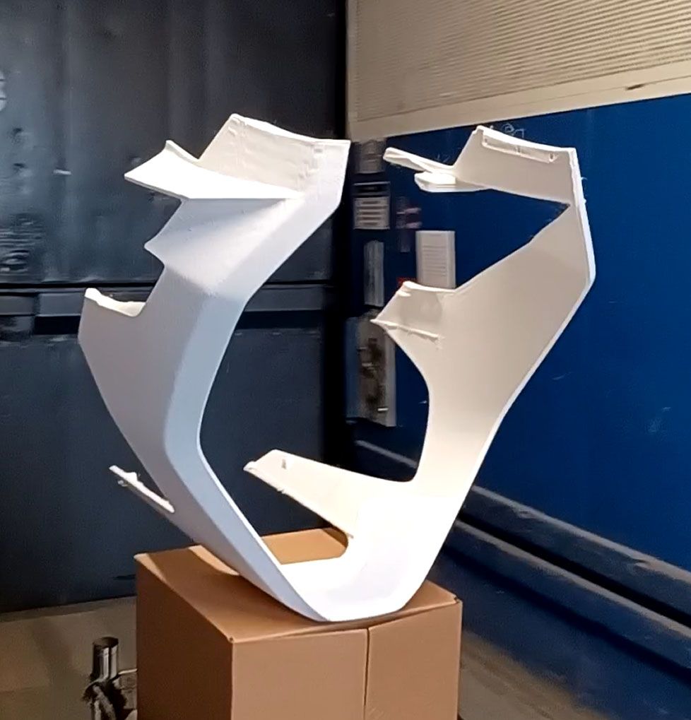
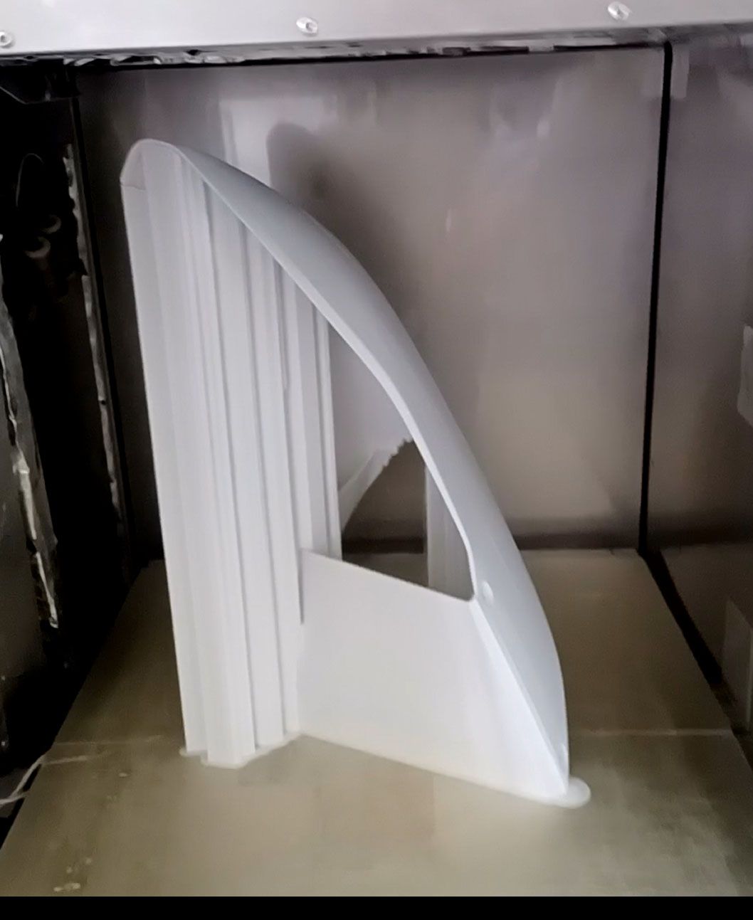
Happy 4th of July everybody.
Those laydown prints of the front upper sides worked well. Here's a pic of the nearly finished product. All the red, white, and blue body panels were printed out. And the black seat 'pads'.

I'm going to keep refining the slicer settings and printing more parts as I make updates to the design, but for now can consider this a completely successful printer build project.
Thanks to the forum for all the suggestions and to the Duet3D crew for such an excellent product line.