I could use some help
-
@alankilian that’s great that you found that picture of one of my wires.
-
@alankilian I’m wondering what you’re thinking, re: editing the endstops? The problem I think I’m having is the print-head isn’t getting to the endstops. Are you suggesting that the endstops are invisible because they are portrayed incorrectly? Honestly, if that’s true, that’s brilliant!
-
@mac said in I could use some help:
@alankilian I’m wondering what you’re thinking, re: editing the endstops? The problem I think I’m having is the print-head isn’t getting to the endstops. Are you suggesting that the endstops are invisible because they are portrayed incorrectly? Honestly, if that’s true, that’s brilliant!
No, not invisible at all, just the opposite, in a way.
If you are right that your endstop switches are NO then when they are not touched the board is seeing them as active.
So your X homing G1 H1 moves never happen because G1 H1 moves stop as soon the endstop is active.
For NO switch connections you need the ! character which makes NO connection appear inactive when the endstop switch is not touched.
A better solution is to re-wire the endstop switches to use the COM And NC connections.
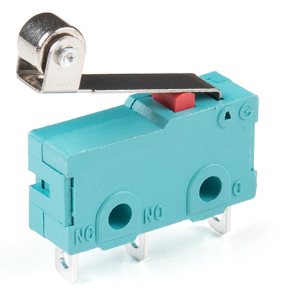
Didn't I post a picture, at one point, of an endstop switch showing the three connections COM, NO and NC?
Here it is in case my memory is faulty.
Frederick
Printers: a small Utilmaker style, a small CoreXY and a E3D MS/TC setup. Various hotends. Using Duet 3 hardware running 3.4.6
-
From the M574 description, since you have a normally-open switch, you shold add the "^" character to your M574 lines:
You wrote
^, but it should be!.Ian
Bed-slinger - Mini5+ WiFi/1LC | RRP Fisher v1 - D2 WiFi | Polargraph - D2 WiFi | TronXY X5S - 6HC/Roto | CNC router - 6HC | Tractus3D T1250 - D2 Eth
-
@droftarts this is the first time I’m seeing that picture, so, this is all new info to me. To be clear: my endstops should all be inverted? Yes, or no?
-
@droftarts @alankilian I do remember our discussion about rewiring the endstops to use the vacant post. I’ll have to find that comment.
-
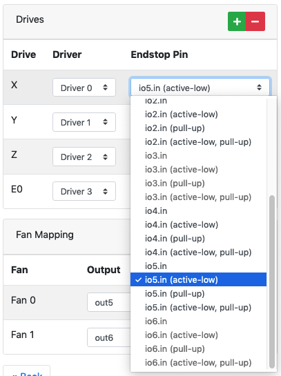
@mac I thought we resolved this in another of your threads? If you're using NO and C on the microswitch, ie NOT the outside two pins, then yes, you need to invert the endstop. In the configurtion tool, on the "I/O Mapping" page, select "io[x].in (active low)" on the drop down list for the endstops wired like this:
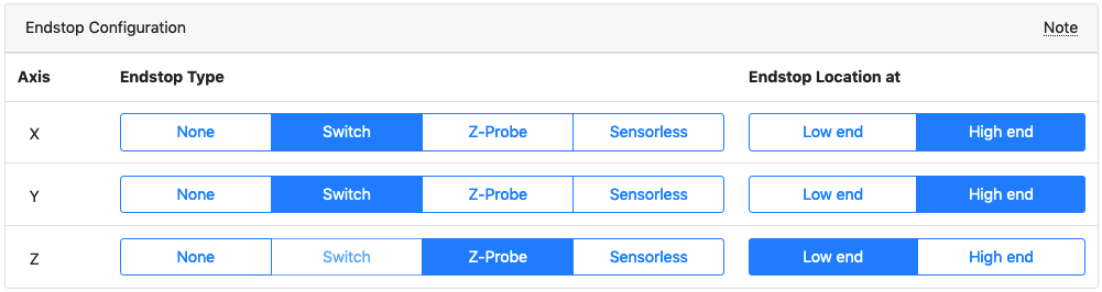
On the "Endstops" page, select Endstop type "Switch" and, because all your endstops are high end, "High end".
This should give the output:
; Endstops
M574 X2 S1 P"!io5.in"                        ; configure switch-type (e.g. microswitch) endstop for high end on X via pin !io5.in
M574 Y2 S1 P"!io6.in"                        ; configure switch-type (e.g. microswitch) endstop for high end on Y via pin !io6.in
M574 Z1 S2                                   ; configure Z-probe endstop for low end on Z

; Z-Probe
M950 S0 C"io3.out"                           ; create servo pin 0 for BLTouch
M558 P9 C"io3.in" H5 F120 T6000              ; set Z probe type to bltouch and the dive height + speeds
G31 P500 X0 Y0 Z2.5                          ; set Z probe trigger value, offset and trigger height
Your homing macros should also output from the configuration tool to suit this setup.
Ian
Bed-slinger - Mini5+ WiFi/1LC | RRP Fisher v1 - D2 WiFi | Polargraph - D2 WiFi | TronXY X5S - 6HC/Roto | CNC router - 6HC | Tractus3D T1250 - D2 Eth
-
@droftarts @alankilian Okay, COM is O on the switch pictured. So using the COM (O) and the NC posts, the white wire should go to the NC (Signal), and the green wire should go to the COM (O) (GND)? I’m trying to visualize the IO_5 (X), IO_6 (Y), and IO_2 (Z) connections on the board.
-
@droftarts you’ve been busy! To be clear, these setting are the software solution versus rewiring the switches.
And, they include reinstalling the Z-probe (BLTouch). Is that what I’m seeing?
-
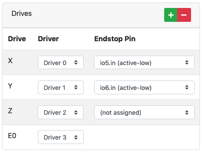
@droftarts @alankilian Interesting the Driver 2 is “unassigned,” to accommodate the Z-pride in its own assignment area of the software.
-
@mac I updated my post so it looks more like your setup. I'd chosen the wrong pins.
As I've said before, it doesn't matter which way around you wire a switch to the pins on the Duet. If you are using C and NO, wire one to the IO header GND, and one to io[x].in. Same if you are using C and NC. It's just the signal is different, so that needs changing in the configuration.
Think of it this way;
- NC means Normally Closed. In a circuit, the switch in 'ON'. A light bulb in the circuit would be on. If you flick the switch, the light bulb turns off.
- NO means Normally Open. In a circuit, the switch is 'OFF'. A light bulb in the circuit would be off. If you flick the switch, the light bulb turns on.
The Duet doesn't mind which way it's wired, it just need to know the way you want the logic to work.
The answer, really, is to test your endstops before relying on the homing macro to be correct. For each endstop, send M119 in DWC. This will report the state of the endstop. Then press and hold the endstop, and send M119 again. The state of the endstop should change. When it's not pressed, it should say "not stopped". When it is pressed, it should say "at max stop" (or "at min stop" if that's the way it's been configured.
Ian
-
@mac
To be clear, these setting are the software solution versus rewiring the switches.
Yes
And, they include reinstalling the Z-probe (BLTouch). Is that what I’m seeing?
You've got one, it was working, may as well use it!
Interesting the Driver 2 is “unassigned,” to accommodate the Z-
prideprobe in its own assignment area of the software.Yes. But... you can have a Z endstop as well, if you want. Generally, best to use the Z probe for Z homing, but there are cases when it's good to have another option. If your printer stops mid-print (eg power failure), the Duet can save the position in the current file (it detects the power drop and quickly saves this info before power completely disappears). When power is back on, and assuming you want resume the print, how do you home the printer? X and Y is usually fine to home, but homing Z with the probe will probably cause it to hit the print. In this case, if you set up a max Z endstop, the printer can home Z to the top of the frame (as your printer moves the X axis up on Z), and then continue with the print.
Ian
Bed-slinger - Mini5+ WiFi/1LC | RRP Fisher v1 - D2 WiFi | Polargraph - D2 WiFi | TronXY X5S - 6HC/Roto | CNC router - 6HC | Tractus3D T1250 - D2 Eth
-
@droftarts "In this case, if you set up a max Z endstop, the printer can home Z to the top of the frame (as your printer moves the X axis up on Z), and then continue with the print."
Is a "max Z endstop" a virtual endstop (versus the real z-stop)? Is it a record of the elevation when the printer lost power, that is used to return to the print with?
Mac
-
@droftarts does selecting Z-Probe render the Low end selection moot? Is that why your picture didn't show Z as "High end?"
-
@fcwilt now THAT! is an endstop! (referring to the picture of the lovely blue endstop)
-
@droftarts I learned yesterday that there are two settings for Microstepping: x32 and x32 (on). I had changed my settings to x32 (on) because the Xvico board has a 32 bit processor. I thought they would use 32 (bit?) microstepping, so to be inline with their choices, I should use those choices on my board.
What's the difference? Can I use an even higher setting to get more microstepping?
Mac
-
@mac said in I could use some help:
Is a "max Z endstop" a virtual endstop (versus the real z-stop)? Is it a record of the elevation when the printer lost power, that is used to return to the print with?
No, it's a real endstop, just at the top of the frame. When power is lost, all the Duet can do is record the current position. When it is turned back on, the printer needs to be homed in all three axes, so that it can resume at that position. So the X axis gets lifted in Z until the Z endstop is triggered, which then gives the machine the Z position. Basically, it's just two different ways of finding Z home, depending on the circumstances.
does selecting Z-Probe render the Low end selection moot? Is that why your picture didn't show Z as "High end?"
Selecting Z Probe forces the homing macros to use the Z probe for Z homing. Your Z probe can't measure at the high end. (Theoretically you could use a probe at the max end, but you would need to mount it at the top of the machine, and then you wouldn't be able to probe the rest of the bed with it, so it would be the same as fitting a microswitch there.)
Ian
Bed-slinger - Mini5+ WiFi/1LC | RRP Fisher v1 - D2 WiFi | Polargraph - D2 WiFi | TronXY X5S - 6HC/Roto | CNC router - 6HC | Tractus3D T1250 - D2 Eth
-
@droftarts this is where I post a funny picture of myself with my eyes crossed. Maybe I'm using my hands to suggest that my head is about to explode.
-
@droftarts said in I could use some help:
Generally, best to use the Z probe for Z homing
I will offer a different opinion here.
I prefer homing with a Z endstop sensor.
Homing with a Z probe requires that X and Y be homed first and that code includes short Z movements to be sure the nozzle is clear of the bed while moving X and Y.
With a Z endstop sensor you can home Z first and usually at a faster speed then you can with a Z probe.
And since Z is homed first you need no Z movements when homing X and Y.
I have both "low" and "high" Z endstop sensors which can be "enabled" as needed via M574 commands.
Again, just my opinion.
Frederick
-
@droftarts can I put a date after a generated config.g file? I'm saving all of them, and right now, the only way I've found that I can keep track of them is to order them in a folder as "Most Current."